

Page 1
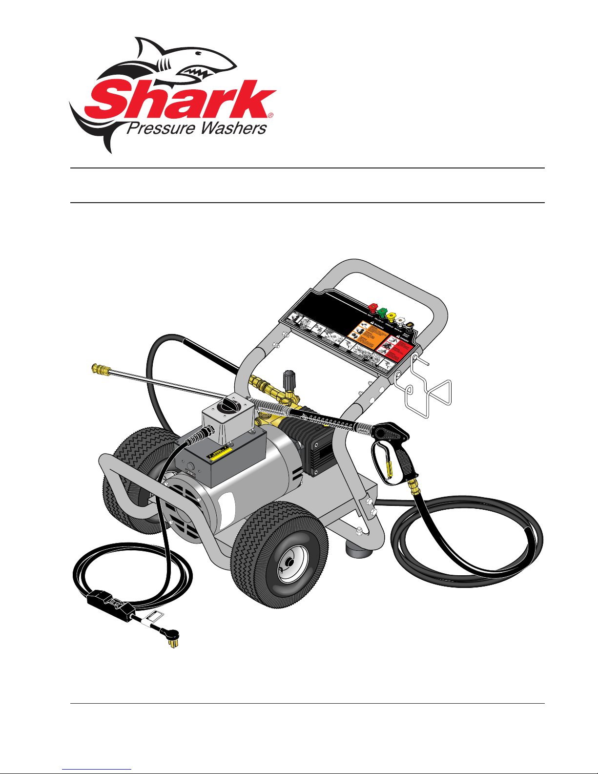
MODEL: DE
OPERATING INSTRUCTION
AND PARTS MANUAL
■ DE-2010 ■ DE-2015 ■ DE-3010 ■ DE-3520
For technical assistance or the SHARK dealer nearest you, call 1-800-771-1881
or visit our website at www.shark-pw .com
97-710
Page 2

CONTENTS
Important Safety Information................................................................3-4
Component Identification ........................................................................ 5
Assembly Instructions.............................................................................6
Operating Instructions.............................................................................7
Applying Detergent and General Operating Techniques..........................8
Shut Down and Clean-Up .......................................................................9
Storage ................................................................................................... 9
Troubleshooting .................................................................................... 10
Preventativ e Maintenance.....................................................................11
Oil Change Record ............................................................................... 11
Exploded View ...................................................................................... 12
Exploded View Parts List .................................................................13-14
Hose and Spray Gun Assembl y............................................................ 15
PDE4-30025A, B, C Exploded View ...................................................... 16
PDE4-30025A, B, C Parts List ..............................................................17
Specifications ....................................................................................... 18
Warranty
Model Number ______________________________
Serial Number ______________________________
Date of Purchase ____________________________
The model and serial numbers will be found on a decal attached to
the pressure washer. You should record both serial number and
date of purchase and keep in a safe place f or future reference.
2
96-720, 97-708, 97-709, 97-710 • REV. 8/04
Page 3
INTRODUCTION
Thank you for purchasing this Pressure Washer.
All information in this manual is based on the latest
product information available at the time of printing.
Manufacturer reserve the right to make changes at an y
time without incurring any obligation.
Owner/User Responsibility:
The owner and/or user must hav e an understanding of
the manufacturer’ s operating instructions and warnings
before using this pressure washer. Warning information should be emphasized and understood. If the operator is not fluent in English, the manufacturer’s instructions and warnings shall be read to and discussed
with the operator in the operator’ s native language by
the purchaser/owner, making sure that the operator
comprehends its contents.
Owner and/or user must study and maintain for future
reference the manufacturers’ instructions.
This manual should be considered a permanent
part of the machine and should remain with it if
machine is resold.
When ordering parts, please specify model and
serial number .
IMPORTANT SAFETY
INFORMATION
CAUTION
READ OPERATOR’S
MANUAL THOROUGHL Y
PRIOR TO USE.
2. All installations must comply with local codes. Contact your electrician, plumber, utility company or
the selling distributor for specific details. To comply with the National Electrical Code (NFPA 70)
and provide additional protection from risk of electric shock, single phase pressure washers are
equipped with a UL approved ground fault circuit
interrupter (GFCI) power cord. Three phase machines must be connected to a GFCI circuit breaker .
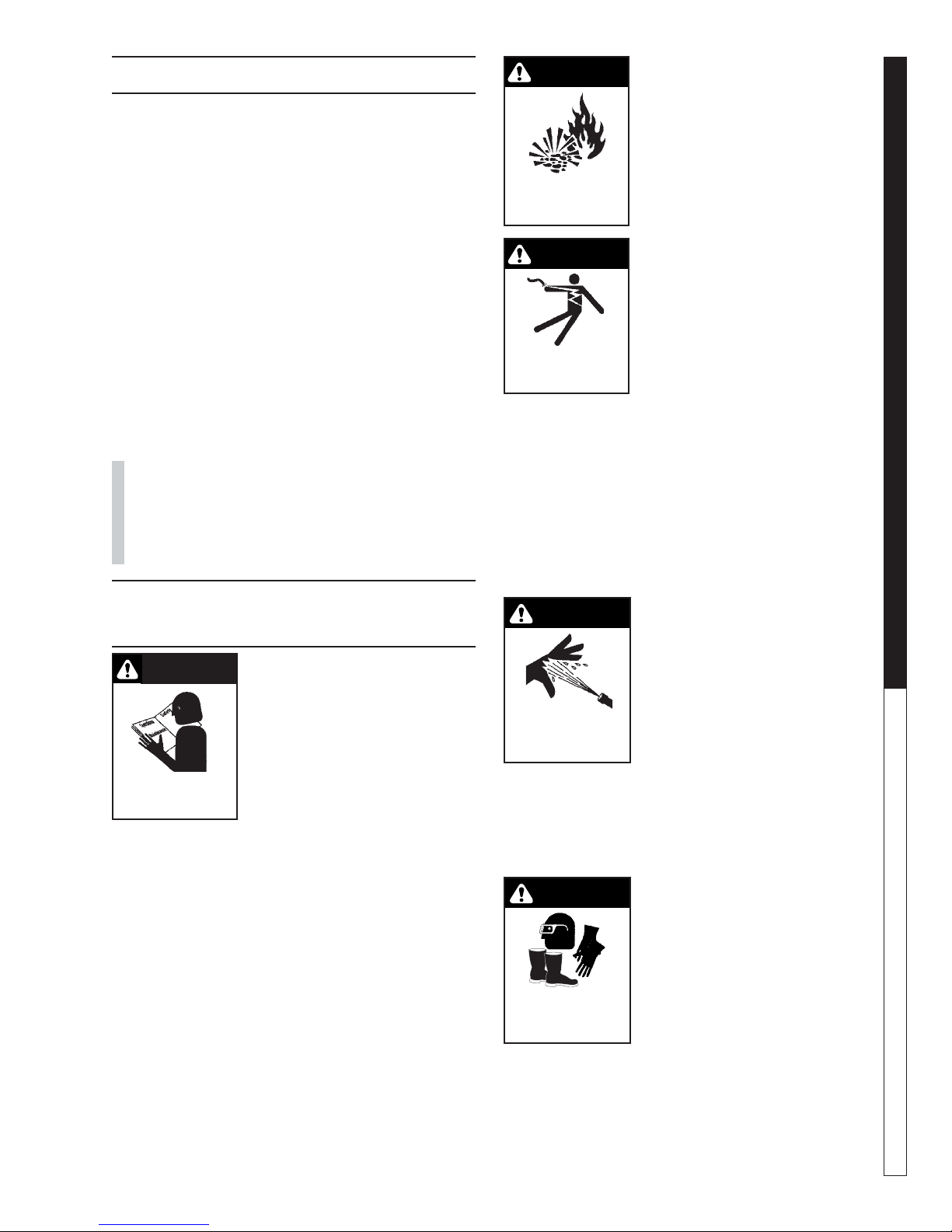
CAUTION: To reduce the risk of
injury, read operating instructions carefully before using.
1. Read the owner's manual
thoroughly. Failure to follow
instructions could cause malfunction of the machine and
result in death, serious bodily
injury and/or property damage.
WARNING
WARNING: Flammable liquids
can create fumes which can ignite causing property damage
or severe injury .
WARNING: Risk of explosion —
Do not spray flammable liquids.
RISK OF EXPLOSION:
DO NOT SPRAY
FLAMMABLE LIQUIDS.
3. Do not operate in an area
where flammable or explosiv e
materials are used or stored.
WARNING
WARNING: Keep water spray
away from electrical wiring or
fatal electric shock may result.
4. To protect the operator from
electrical shock, the machine
must be electrically grounded.
KEEP WA TER SPRA Y
AWAY FROM
ELECTRICAL WIRING.
It is the responsibility of the
owner to connect this machine to a UL grounded re-
ceptacle of proper voltage and amperage ratings.
Do not spray water on or near electrical compo-
nents.
Do not touch machine with wet hands or while
standing in water. Alwa ys disconnect power before
servicing.
5. Grip cleaning wand securely with both hands before starting the cleaner. Failure to do this could
result in injury from a whipping wand.
WARNING
WARNING: High pressure
stream of fluid that this equipment can produce can pierce
skin and its underlying tissues,
leading to serious injury and
possible amputation.
HIGH PRESSURE
SPRAY CAN PIERCE
SKIN AND TISSUES.
6. High pressure developed by
these machines will cause
personal injury or equipment
damage. Use caution when operating. Do not direct discharge stream at people, or severe injur y
or death will result.
7. Never make adjustments on machine while in
operation.
WARNING
WARNING: High pressure spray
can cause paint chips or other
particles to become airborne
and fly at high speeds.
8. Eye safety devices, f oot, hand
PROTECTIVE
EYEWEAR AND
CLOTHING MUST BE
WORN.
and other protective clothing
must be worn when using this
equipment.
9. Do not operate with the spray
gun trigger in the off position for extensiv e periods
of time as this may cause damage to the pump.
10. The best insurance against an accident is precaution and knowledge of the machine.
PRESSURE W ASHER
OPERATOR’S MANUAL
3
96-720, 97-708, 97-709, 97-710 • REV. 8/04
Page 4

11. Manufacturer will not be liable for any changes
made to our standard machines, or any components not purchased from us.
12. Be certain all quick coupler fittings are secured before using pressure washer .
13. Never run pump dry or leave spray gun closed
longer than 5 minutes.
14. Inlet water supply must be cold and clean fresh
water.
15. Do not allow children to operate the pressure
PRESSURE W ASHER
washer at any time.
16. Protect from freezing.
17. When the machine is working, do not cover or place
in a closed space where ventilation is insufficient.
OPERATOR’S MANUAL
4
96-720, 97-708, 97-709, 97-710 • REV. 8/04
Page 5
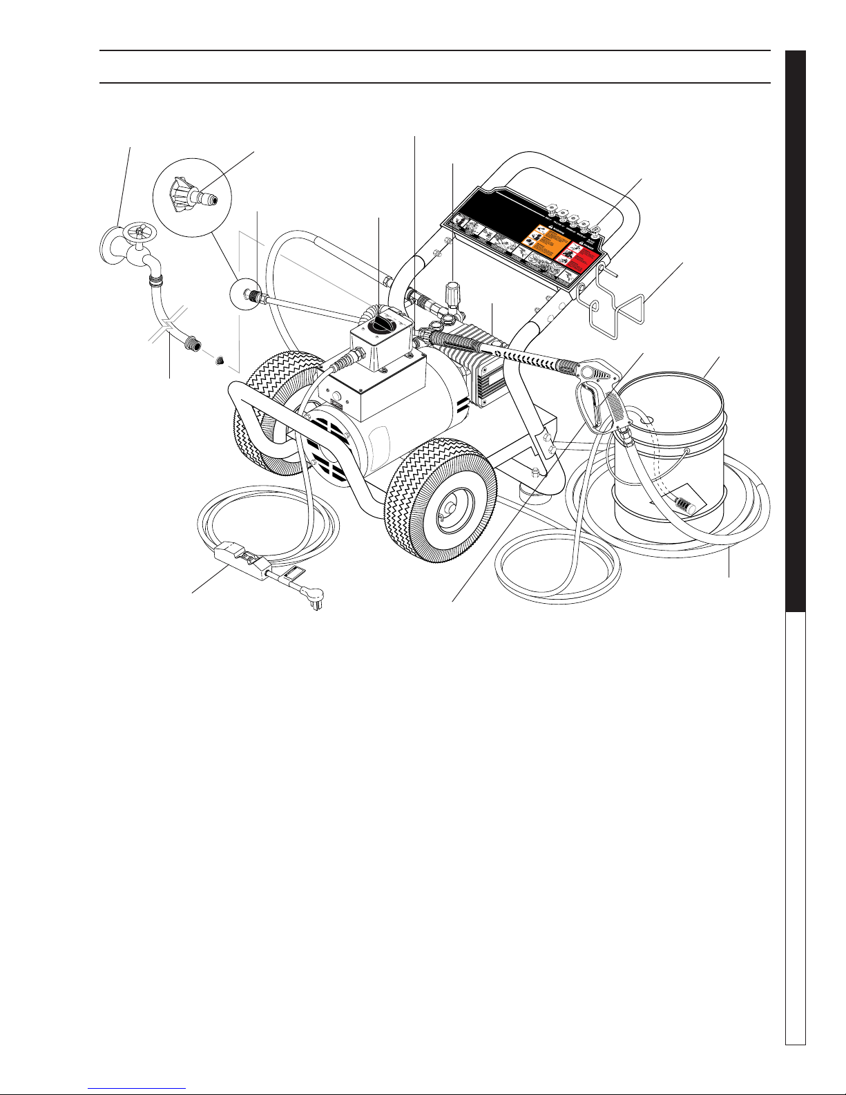
COMPONENT IDENTIFICATION
PRESSURE W ASHER
Water Supply
(not included)
Garden Hose
(not included)
Pressure
Nozzle
Quick
Coupler
On/Off
Switch
Pump
Protector
Unloader
Pump
Soap
Nozzle
Safety
Latch
Wand
Hanger
Detergent
Bucket (not
included)
OPERATOR’S MANUAL
GFCI
Pump — Dev elops high pressure.
Spray Gun — Controls the application of water and
detergent onto cleaning surface with trigger device. Includes safety latch.
Detergent Injector — Allows you to siphon and mix
detergents when used with a soap nozzle.
Wand — Must be connected to the spra y gun.
Unloader — Safety device that relie ves pressure when
spray gun trigger is closed.
High Pressure
Spray Gun
and Wand
High Pressure Hose — Connect one end to water
pump discharge nipple and the other end to spray gun.
Pump Protector — Cycles fresh cool water through
pump when recirculating water reaches 140°F.
GFCI — Ground fault circuit interrupter trips when volt-
age leaks to ground.
Note: If trigger on spray gun is released for more
than 2 minutes, water will leak from valve. Warm
water will discharge from pump protector onto
floor . This system pre vents internal pump damage.
Hose
5
96-720, 97-708, 97-709, 97-710 • REV. 8/04
Page 6
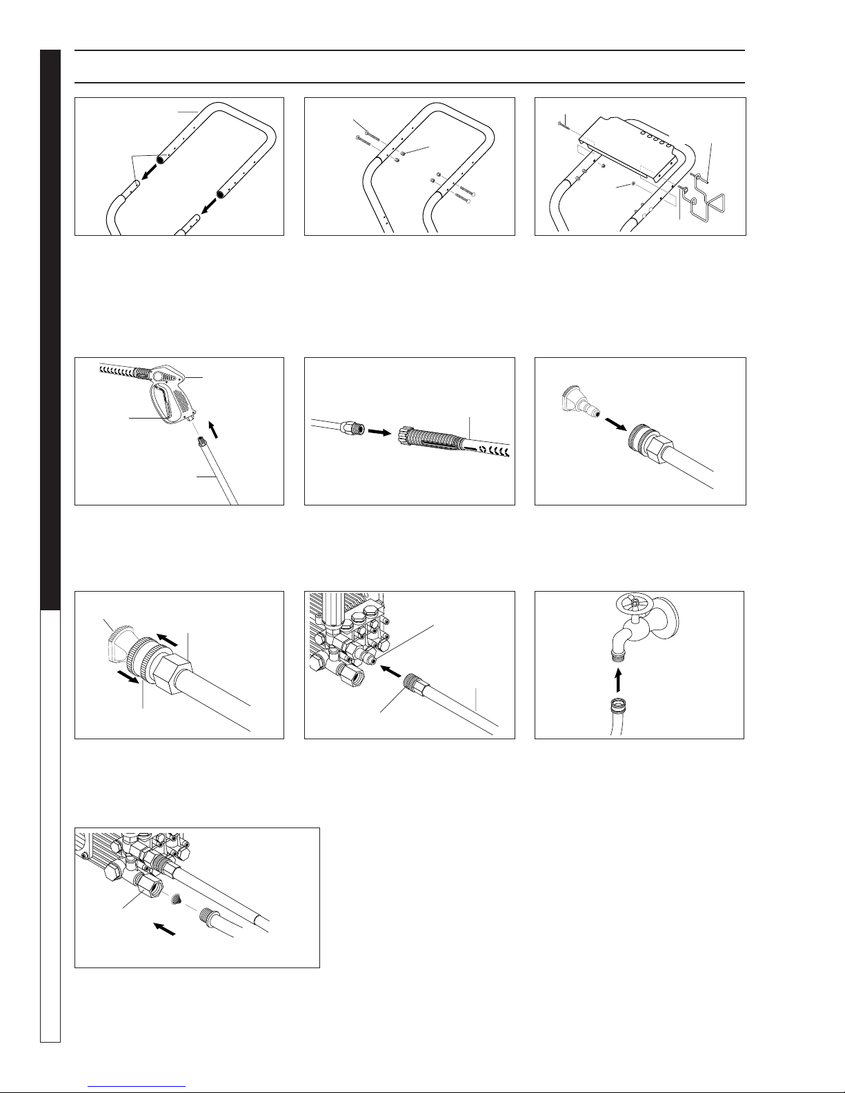
ASSEMBLY INSTRUCTIONS
Handle
Alignment
Holes
Frame
Assy.
PRESSURE W ASHER
STEP 1: Attach the handle to the
frame of the pressure washer.
Note: It ma y be necessary to move
the handle supports from side to
side in order to align the handle so
it will slide over the frame supports.
Spray
OPERATOR’S MANUAL
Safety
Latch
High Pressure
Hose
Gun
Carriage
Bolt
Nut
STEP 2: Insert the carriage bolt
through the holes from the outside
of the unit and attach a nut from
the inside of the machine. Tighten
nuts.
Spray
Gun/Wand
Nozzle
Extension
Bolts
Nut
Hose/Gun
Storage
Bracket
Studs
STEP 3: Attach the spray gun/hose
storage handle, and bracket to
handle. Tighten nuts.
Pressure
Nozzle
Wand
Coupler
STEP 4: Attach the high pressure
hose to the spray gun using teflon
tape on hose threads.
Pressure
Nozzle
Wand
Collar
Wand
Coupler
STEP 7: Release the coupler col-
lar and push the nozzle until the
collar clicks. Pull the nozzle to
make sure it is seated properly.
Pump
Water Inlet
Garden
Hose
STEP 10: Connect the garden hose to
pump water inlet. Inspect inlets.
CAUTION: Do not run the pump without water or pump damage will result.
6
STEP 5: Attach nozzle extension
to spray gun/wand. Tighten both
by hand.
Pump Discharge
Fitting
High
Pressure
Hose
Coupler Collar
STEP 8: Connect the high pressure
hose to the pump discharge fitting.
Push coupler collar forward until
secure.
96-720, 97-708, 97-709, 97-710 • REV. 8/04
STEP 6: Pull the spring-loaded collar of the wand coupler back to insert your choice of pressure nozzle.
Cold
Water
Source
Garden
Hose
STEP 9: Connect garden hose to
the cold water source.
Page 7

OPERATING INSTRUCTIONS
R
I
M
C
H
A
U
D
!
O
I
L
A
L
E
R
T
W
H
E
N
O
I
L
L
E
V
E
L
L
O
W
,
E
N
G
I
N
E
S
T
O
P
S
I
M
M
E
D
I
A
T
E
L
Y
.
R
E
A
D
O
W
N
E
R
’
S
M
A
N
U
A
L
B
E
F
O
R
E
O
P
E
R
A
T
I
O
N
.
L
I
R
E
L
E
M
A
N
U
E
L
D
’
U
T
I
L
I
S
A
T
E
U
R
A
V
A
N
T
U
S
A
G
E
.
V
O
R
I
N
B
E
T
R
I
E
B
N
A
H
M
E
U
N
B
E
D
I
N
G
T
B
E
D
I
E
N
U
N
G
S
A
N
L
E
I
T
U
N
G
D
U
R
S
C
H
L
E
S
E
N
.
N
O
U
T
I
L
I
Z
A
R
S
I
N
A
N
T
E
S
N
O
H
A
B
E
R
L
E
I
D
O
E
L
M
A
N
U
A
L
.
G
a
r
d
e
n
H
o
s
e
W
a
t
e
r
S
u
p
p
l
y
H
i
g
h
P
r
e
s
s
u
r
e
H
o
s
e
O
I
L
A
L
E
R
T
W
H
E
N
O
I
L
L
E
V
E
L
L
O
W
,
E
N
G
I
N
E
S
T
O
P
S
I
M
M
E
D
I
A
T
E
L
Y
.
R
E
A
D
O
W
N
E
R
’
S
M
A
N
U
A
L
B
E
F
O
R
E
O
P
E
R
A
T
I
O
N
.
L
I
R
E
L
E
M
A
N
U
E
L
D
’
U
T
I
L
I
S
A
T
E
U
R
A
V
A
N
T
U
S
A
G
E
.
V
O
R
I
N
B
E
T
R
I
E
B
N
A
H
M
E
U
N
B
E
D
I
N
G
T
B
E
D
I
E
N
U
N
G
S
A
N
L
E
I
T
U
N
G
D
U
R
S
C
H
L
E
S
E
N
.
N
O
U
T
I
L
I
Z
A
R
S
I
N
A
N
T
E
S
N
O
H
A
B
E
R
L
E
I
D
O
E
L
M
A
N
U
A
L
.
Cold
Water
Source
PRESSURE W ASHER
Garden
Hose
STEP 1: Connect garden hose to the
cold water source and turn water on
completely. Nev er use hot w ater.
On/Off
Switch
STEP 4: Tur n machine on by turn-
ing switch at top of motor .
STEP 2: T rigger the spray gun to
eliminate trapped air then wait
for a steady flow of water to
emerge from the spray nozzle.
Safety
Latch
WARNING! Never replace
nozzles without engaging the
safety latch on the spray gun trigger.
STEP 4: Connect to appropriate
power supply. Push reset button on
GFCI.
OPERATOR’S MANUAL
NOZZLES
7
T
E
O
A
O
S
P
Y
E
S
R
T
A
E
T
P
E
S
U
N
IT
O
W
R
N
B
E
E
E
A
R
F
D
’S
G
O
a
M
R
s
E
A
U
N
S
U
IN
A
L
G
!
1
.
C
O
H
i
O
E
l
N
C
I
L
o
K
A
z
C
E
z
L
o
N
l
e
N
u
E
D
G
p
C
V
G
l
o
I
E
e
N
l
A
r
L
l
E
a
S
S
r
.
2
.
IN
S
W
N
T
P
O
A
a
R
n
Z
L
E
d
Z
L
S
L
H
S
E
U
IG
I
R
N
H
E
W
A
N
D
.
3
.
C
A
O
N
N
D
N
T
H
U
E
I
R
G
C
N
T
H
G
W
P
A
R
A
R
E
T
S
D
E
S
E
R
U
N
S
R
U
E
P
H
P
L
Y
O
The five color-coded quick connect nozzles provide a wide array of spray
widths from 0° to 45° and are easily accessible when placed in the conv enient rubber nozzle holder, which is pro vided on the front of the machine.
NOTE: F or a more gentle rinse, select the white 40° or green 25° nozzle.
T o scour the surf ace, select the yellow 15° or red 0° nozzle . To apply detergent select the black nozzle.
R
E
D
0
¡
YELLOW 15¡
GREEN 25¡
WARNING
WHITE 40¡
H
O
S
O
E
S
E
.
N
.
A
4
.
T
R
G
IG
U
N
G
IR
E
T
R
O
F
C
R
R
S
h
O
P
E
o
R
M
k
L
e
A
IE
H
Y
V
O
E
S
F
E
u
S
V
e
l
.
a
l
v
e
C
H
A
U
D
!
E
5
n
C
.
g
S
H
O
i
n
w
O
P
e
i
K
E
t
c
T
P
E
N
R
E
A
D
O
W
N
E
R
L
’
I
S
R
E
M
L
A
E
N
U
M
h
A
A
L
N
V
U
B
O
E
E
R
L
F
I
O
N
D
R
B
’
U
E
E
T
T
O
I
R
L
P
I
I
S
E
E
A
B
R
T
N
A
E
T
A
U
N
I
H
O
R
O
M
N
A
U
E
.
V
T
U
B
A
I
L
N
E
N
O
I
D
B
T
Z
I
A
E
E
U
D
R
N
S
I
U
A
N
S
u
N
G
I
G
N
G
E
T
A
.
S
N
A
T
N
E
,
L
S
E
I
N
T
O
U
N
H
G
A
B
D
E
U
R
R
S
L
C
E
I
H
D
L
O
E
S
E
E
L
N
M
.
A
N
U
A
L
.
F
S
l
T
"
l
U
t
U
O
a
E
R
r
N
L
t
N
"
V
E
,
S
A
N
T
L
G
A
V
I
E
R
N
,
T
E
S
E
S
E
N
W
T
G
I
T
IN
C
E
H
.
E
n
g
S
i
n
w
e
i
t
6
c
C
. W
E
h
O
N
M
H
G
E
P
IN
N
L
E
E
J
S
T
O
E
W
B
D
IT
I
,
S
T
C
U
H
R
T
N
O
O
7
F
. T
F
T
R
.
O
I
G
F
R
R
G
E
O
E
L
(SOAP)
DANGER
BLACK
96-720, 97-708, 97-709, 97-710 • REV. 8/04
7
Page 8

DETERGENTS AND GENERAL OPERATING TECHNIQUES
WARNING
WARNING: Some detergents may
be harmful if inhaled or ingested, causing severe nausea,
fainting or poisoning. The harmful elements may cause property damage or severe injury.
PRESSURE W ASHER
STEP 1: Connect detergent injector to discharge nipple
on machine. Connect high pressure hose to injector
with quick coupler. (Check to make sure locking coupler sleeves are in proper position bef ore applying water
pressure).
Discharge
Nipple
OPERATOR’S MANUAL
Detergent
Injector
Quick
Coupler
Soap Nozzle
THERMAL PUMP PRO TECTION
If you run the motor on your pressure washer for 3-5
minutes without pressing the trigger on the spray gun,
circulating water in the pump can reach high temperatures. When the water reaches this temperature, the
pump protector engages and cools the pump by discharging the warm water onto the ground. This thermal
device pre vents internal damage to the pump .
CLEANING TIPS
Pre-rinse cleaning surface with fresh water . Place detergent suction tube directly into cleaning solution and apply
to surface at low pressure (for best results, limit your work
area to sections approximately 6 feet square and always
apply detergent from bottom to top). Allow detergent to
remain on surface 1-3 minutes. Do not allow detergent to
dry on surface. If surface appears to be drying, simply
wet down surface with fresh w ater . If needed, use brush
to remove stubborn dirt. Rinse at high pressure from top
to bottom in an even sweeping motion keeping the spray
nozzle approximately 1 foot from cleaning surface. Use
overlapping strokes as you clean and rinse any surface.
For best surface cleaning action spray at a slight angle.
Filter
STEP 2: Use detergent designed
specifically for pressure washers.
Household detergents could damage the pump. Prepare detergent
solution as required by the manufacturer . Fill a container with pressure washer detergent. Place the
filter end of detergent suction tube
into the detergent container.
STEP 3: With safety latch on spr ay
gun engaged, secure black detergent nozzle into quick coupler.
NOTE: Detergent cannot be applied using a pressure nozzle.
STEP 4: With the motor running, pull trigger to operate
machine. Liquid detergent is drawn into the machine
and mixed with water . Apply detergent to work area. Do
not allow detergent to dry on surface.
Recommendations:
• Before cleaning any surface, an inconspicuous area
should be cleaned to test spray pattern and distance for maximum cleaning results.
• If painted surfaces are peeling or chipping, use extreme caution as pressure washer may remo ve the
loose paint from the surface.
• Keep the spray nozzle a saf e distance from the surface you plan to clean. High pressure wash a small
area, then check the surface f or damage. If no damage is found, continue to pressure washing.
CAUTION - Never use:
• Bleach, chlorine products and other corrosive
chemicals
• Liquids containing solvents (i.e., paint thinners,
gasoline, oils)
• Tri-sodium phosphate products
• Ammonia products
• Acid-based products
These chemicals will harm the machine and will damage the surface being cleaned.
RINSING
IMPORT ANT : You must flush the deter gent injection
system after each use by placing the suction tube
into a bucket of clean water , then run the pressure
washer in low pressure for 1-2 minutes.
8
• It will take a fe w seconds for the detergent to clear .
Apply safety latch to spra y gun. Remo ve black soap
nozzle from the quick coupler. Select and install
the desired high pressure nozzle. NOTE: You can
also stop detergent from flowing by simply removing detergent siphon tube from bottle.
96-720, 97-708, 97-709, 97-710 • REV. 8/04
Page 9

STEP 1: Remove deter-
CAUTION
gent suction tube from
container and insert into
one gallon of fresh water .
Slide nozzle forward for
low pressure or use black
detergent nozzle. Pull trigger on spray gun and siphon fresh clean water for
one minute.
SHUTTING DO WN AND CLEAN-UP
On/Off
Switch
STEP 2: T urn off machine
by turning switch to “OFF”
switch.
STEP 3: Turn off water
supply.
STEP 4: Press trigger to release water pressure.
PRESSURE W ASHER
OPERATOR’S MANUAL
Pump
Water
Inlet
STEP 5: Disconnect the
garden hose from the water inlet on the machine.
High Pressure Outlet
STEP 6: Disconnect the
high pressure hose from
high pressure outlet.
STORAGE
Pump Storage
CAUTION: Always store your pressure washer in a location where the
temperature will not fall below 32°F
(0°C). The pump in this machine is
susceptible to permanent damage if
frozen.
FREEZE DAMAGE IS NOT CO VERED BY WARRANTY.
If you must store your pressure washer in a location
where the temperature is below 32°F, you can minimize
the chance of damage to your machine by draining your
machine as follows:
1. Stop the pressure washer and detach supply hose
and high pressure hose. Squeeze trigger of spray
gun to drain all water from the wand and hose.
2. Restart pressure washer and let it run briefly (about
5 seconds) until water no longer discharges from
the high pressure outlet.
96-720, 97-708, 97-709, 97-710 • REV. 8/04
Safety
Latch
STEP 7: Engage the
spray gun saf ety lock.
9
Page 10

TROUBLESHOOTING
PROBLEM POSSIBLE CAUSE SOLUTION
PUMP RUNNING
NORMALLY BUT
PRESSURE LOW ON
INSTALLATION
FLUCTUATING PRESSURE
PRESSURE LOW AFTER
PERIOD OF NORMAL USE
PUMP NOISY
PRESSURE WASHER Troubleshooting Guide
PRESENCE OF WATER IN
PUMP OIL
WATER DRIPPING FROM
UNDER PUMP
WATER DRIPPING FROM
PUMP PROTECTOR
OIL DRIPPING
EXCESSIVE VIBRATION IN
HIGH PRESSURE HOSE
MOTOR DOES NOT START
WHEN SWITCHED ON
WHEN SWITCHING ON THE
MACHINE, MOTOR HUMS
BUT DOES N OT RUN
MOTOR STOPS
Pump sucking air Check water supply and possibility of air seepage.
Check valves sticking Check and clean or replace if necessary.
Unloader valve seat faulty Check and replace if necessary.
Nozzle incorrectly sized Check and replace if necessary.
Worn piston packing Check and replace if necessary.
Valves worn Check and replace if necessary.
Blockage in valve Check and replace if necessary.
Pump sucking air Check water supply connections.
Worn piston packing Check and replace if necessary.
Insufficient water Check filter and hose for breakage.
Nozzle worn Check and replace if necessary.
Suction or delivery valves worn Check and replace if necessary.
Suction or delivery lines blocked Check and clean if necessary.
Unloader valve seat worn Check and replace if necessary.
Worn piston packing Check and replace if necessary.
Water temperature excessive Reduce to below 160
Air in suction line Check water supply and connections on suction line.
Broken or weak suction or delivery
valve spring
Foreign matter in valves Check and clean if necessary.
Worn bearings Check and replace if necessary.
Excessive temperature of water Reduce to below 160
Oil seal worn Check and replace if necessary.
High humidity in air Check and replace if necessary.
Piston packing worn Check and replace if necessary.
Piston packing worn Check and replace if necessary.
O-ring plunger retainer wor n Check and replace if necessary.
Water supply pressure too high (over
90 PSI)
Spray gun is in the off position for over
5 minutes
Oil seal worn Check and replace if necessary.
Irregular functioning of the pump
valves
Plug not well connected or lack of
power supply
Main voltage is insufficient, lower than
the minimum required
The pump is stuck or frozen Check by turning the motor manually.
Tripped ther mal overload due to
overheating
Check and replace if necessary.
Lower water supply pressure using a regulator.
Turn machine off if not in use for over 5 minutes.
Check and replace if necessary.
Check plug, cable and switch.
Check to make sure main power supply is adequate.
Check that main voltage corr esp onds t o th e
specificati ons. Wait a few minutes before turning on
the machine again by reset t i ng t he GFCI cor d.
o
F.
o
F.
10
96-720, 97-708, 97-709, 97-710 • REV. 8/04
Page 11

PREVENTATIVE MAINTENANCE
PREVENTATIVE MAINTENANCE
This pressure washer was produced with the best av ailable materials and quality craftsmanship. How ev er, y ou
as the owner hav e certain responsibilities for the correct care of the equipment. Attention to regular pre v entative maintenance procedures will assist in preserving the performance of your equipment. Contact your dealer
for maintenance. Regular preventative maintenance will add many hours to the life of your pressure washer.
Perf orm maintenance more often under severe conditions.
MAINTENANCE SCHEDULE
Inspect Daily inspect the oil level
Pump Oil
Change After first 50 hours, then every 500 hours or annually
Replace High Pressure Nozzle Every 6 months
Replace Quick Connects Annually
Clean Water Screen/Filter Weekly
Replace HP Hose Annually if there is any sign of wear
Grease Motor Every 10,000 hours
PRESSURE WASHER Troubleshooting Guide
OIL CHANGE RECORD
Check pump oil and engine oil lev el before first use of y our new pressure washer .
Estimated Operating
Date Oil Changed
Month/Day/Year
Hours Since Last
Oil Change
Date Oil Changed
Month/Day/Year
Estimated Operating
Hours Since Last
Oil Change
11
96-720, 97-708, 97-709, 97-710 • REV. 8/04
Page 12

EXPLODED VIEW
PRESSURE W ASHER
OPERATOR’S MANUAL
50
21
2
3
66, 67
10
32
10
11
12
1
13
27
9
65
25
19
18
17
16
14
70
21
15
4
20
201507D
2-15021D
301007D
301009D
301509D
52
32
26
(Models 352009A)
5
23
6, 7
5
15
62
16
24
25
17
26
27
65, 14
28
39 33
21
22
30
31
29
61
39
40
54
44
24
40
8
40
23
15
70
(Model 4-20021A,
1
34
16
14, 65
21
352007A)
35
8
17
22
10
10
66, 67
36
37
38
39
63
60
201007D,
201009D,
2-11021D
53
56
55
12
48
57
49
59
58
48
52
41
68
31
53
41
55
68
96-720, 97-708, 97-709, 97-710 • REV. 8/04
49
48
42
47
43
44
46
45
51
50
Page 13

EXPLODED VIEW PARTS LIST
PRESSURE W ASHER
ITEM PART NO. DESCRIPTION QTY
1 See Specifications Page 18, For Nozzle Size
4-12803015 Nozzle, 1503, Yellow 1
4-12803025 Nozzle, 2503, Green 1
4-12803040 Nozzle, 4003, White 1
4-12803000 Nozzle, 0003, Red 1
4-12804015 Nozzle, 1504, Yellow 1
4-12804025 Nozzle, 2504, Green 1
4-12804040 Nozzle, 4004, White 1
4-12804000 Nozzle, 0004, Red 1
4-12805015 Nozzle, 1505, Yellow 1
4-12805025 Nozzle, 2505, Green 1
4-12805040 Nozzle, 4005, White 1
4-12805000 Nozzle, 0005, Red 1
4-12805515 Nozzle, 1555, Yellow 1
4-12805525 Nozzle, 2555, Green 1
4-12805540 Nozzle, 4055, White 1
4-12805500 Nozzle, 0055, Red 1
4-12806015 Nozzle, 1506, Yellow 1
4-12805025 Nozzle, 2506, Green 1
4-12806040 Nozzle, 4006, White 1
4-12806000 Nozzle, 0006, Red 1
4-16540 Nozzle, Compl. QCME 6540,
Brass, All 1
2 4-011106 Wand, 18" M22 x 1/4" QC 1
3 4-011137 Spray Gun, SK@, 3/8" Inlet,
Lance w/M22 Coupler 1
4 Hose, See Specifications Page 18
5 6-051591 Connector, 1/2" L/T, 90°,
Black (201507D, 2-15021D,
301007D, 301009D, 301509A)2
6 6-0104 Cord, Service, SOWA 12/3,
Coleman (201507D,
2-15021D, 301007D, 301009D,
301509A) 21 in.
7 6-0128 Conduit, Watertight, Flex,
1/2 (201507D, 2-15021D,
301007D, 301009D,
301509A) 8 in.
8 90-2000 Nut, 1/4" ESNA, NC 6
9 4-011184 Injector, Det., Assy, 3-5 GPM 1
10 6-051593 Connector, 3/4" L/T, 90°,
Black (352007A, 352009A,
4-20021A) 2
11 5-18031 Plate, Pump Mount, Hawk
(352009A) 1
90-10302 Bolt,
6mm x 25mm/6mm x3mm
(352009A) 4
90-50094 Key, Step,
8mm x 6mm/6mm x3mm
(352009A) 1
12 90-40091 Washer, 1/2" Lock (352009A)4
13 90-10271 Bolt, 1/2" x 1" Hex, NC HH
(352009A) 4
96-720, 97-708, 97-709, 97-710 • REV. 8/04
ITEM P AR T NO . DESCRIPTION QTY
14 90-1991 Screw, 10/32" x 1/2" BHSOC
Black (201507D, 2-15021D,
301007D, 301009D, 301509A,
352007A, 352009A,
4-20021A) 4
15 6-020204 Switch, 2 Pos. 120V-600V,
1-3 PH Bremas (201507D,
2-15021D, 301007D, 301009D,
301509A, 352007A, 352009A,
4-20021A) 1
16 6-03911 Lid, Plastic, Carlon E9801
Box (201507D, 2-15021D,
301007D, 301009D, 301509A,
352007A, 352009A,
4-20021A) 1
17 6-03910 Box, Plastic, Carlon E9801,
w/o Lid (201507D, 2-15021D,
301007D, 301009D, 301509A,
352007A, 352009A,
4-20021A) 1
18 90-19713 Screw, 5/16" x 3/4" Whiz
(352009A) 2
90-20012 ▲ Nut, 5/16" Flange, Whiz
(352009A) 2
19 95-07500186 Bracket, Switch Box
(352009A) 1
20 6-010631 GFCI, 240V 1Ph 20A, 36'
12-3 Cord (301509A) 1
6-01059 GFCI, 240V 1Ph 30A, 36' 10-3
Cord (352007A, 352009A,
4-20021A) 1
6-01060 GFCI, 120V 20A, w/36' 12-3
Cord (301009D, 301007D,
201507D, 2-15021D) 1
6-01062 GFCI, 120V 15A, w/36'
12-3 Cord (201009D,
201007D, 2-11021D) 1
21 10-08021 Label, Disconnect Power
Supply 1
22 95-07105000 Cover, Motor (201507D,
2-15021D, 301007D, 301009D,
301509A, 4-20021A,
3-52007A) 1
23 2-2006 Nipple, 3/8" x 3/8" NPT, ST
Female 1
24 2-10943 Swivel, 3/8" MP x 3/4" GHF
w/Strainer (PDE, EP) 1
2-10942 Swiv el, 1/2" MP x 3/4" GHF,
w/Strainer (DE, DL) 1
25 2-300816 Protector, Pump, 3/8" PTP
(EP, PDE) 1
2-30082 Protector, Pump, 1/2" PTP
(DL, DE) 1
26 Unloader, See Specifications Page 18
27 Pump, See Specifications Page 18
OPERATOR’S MANUAL
13
Page 14

ITEM PART NO. DESCRIPTION QTY
28 90-1016 Bolt, 3/8" x 1" NC
(All except 352009A) 4
29 90-4002 Washer, 3/8" SAE, Flat
(All except 352009A) 4
30 90-1006 Bolt, 5/16" x 3/4" NC
(All except 352009A) 4
90-1016 Bolt, 3/8" x 1" NC HH
(352009A) 4
31 90-4001 Washer, 5/16" Flat
PRESSURE W ASHER
90-4002 Washer, 3/8" SAE, Flat
32 Motor, See Specifications Page 18
33 2-0103 Grommet, Rubber, Nozzle
34 90-20012 Nut, 5/16" Flange, Whiz
35 95-07104921 Handle, Grab, Red
OPERATOR’S MANUAL
95-07104961 Handle, Grab, Chrome (PDE)1
36 11-0362 Label (EP Models) 1
11-08022 Label (PDE Models) 1
11-0361 Label (DE Models) 1
11-0363 Label (DL Models) 1
37 95-07104945 Plate, War ning/Instr. Red
95-07104966 Plate, W arning/Instr . Blk
38 95-07102382 Hanger, Hose/Wand, 1
39 90-100473 Bolt, Carriage, 1/4"-20 x
40 90-4000 Washer, 1/4" Flat 6
41 90-2001 Nut, 5/16" ESNA, NC 4
42 95-07104920 Handle, Lower Grab, Red
95-07104950 Handle, Lower Grab, Black
43 95-07104923 Retainer Bracket, Handle,
95-07104924 Retainer Bracket, Handle,
44 90-1020 Bolt, 3/8" x 2" 4
45 90-10201 Bolt, 3/8" x 2-1/4" 2
46 90-40125 Washer, 3/8" x 1" 2
47 2-01041 Pad, Soft Rubber, 50 Duro 2
48 90-4002 Washer, 3/8" SAE, Flat 6
49 90-2002 Nut, 3/8" ESNA, NC 6
50 90-200422 Cap, 5/8" Axle Hub, Black 2
51 4-0303 Wheel & Tire Assy., 4" Steel
52 2-01403 Bushing, Snap, 5/8" 2
53 90-10077 Belt, Carriage 5/16" x 1-3/4" 4
54 95-07102313 Axle, 5/8" x 19.625" Long 1
(All except 352009A) 8
352009A) 8
Holder 5
Loc 4
(DE, DL, EP) 1
(EP, DE, DL) 1
(PDE) 1
1-3/4" 6
(DE, DL, EP) 1
(PDE) 1
Red (DE, DL, EP) 2
Black (PDE) 2
Rim w/Tube 2
ITEM P AR T NO . DESCRIPTION QTY
55 90-4001 Washer, 5/16" Flat, SAE 4
56 95-07104922 Handle, Bumper, Red (EP, DL
DE Models) 1
95-07104962 Handle, Bumper, Chrome (PDE
Models) 1
57 95-07104927 Base, CW Direct, Red (EP, DL
DE Models) 1
95-07104965 Base, CW Direct, Black
(PDE Models) 1
58 10-08017 Label, Intended For Outdoor
Use 1
59 10-9999 Label, Clear Lexan, 2-1/4” x
4-1/2" 1
60 6-02049 Switch Assembly (201007D,
201009D, 2-11021D) 1
61 10-08018 Label, Warning, Service
Cord 1
62 6-05154 Strain Relief, Flex 90°, Plastic
(201507D, 2-15021D, 301007D,
301009D, 301509A) 1
63 6-05152 Strain Relief (201007D,
201009D, 2-11021D) 1
6-05181A ▲ Locknut, 1/2" (201007D,
201009D, 2-11021D) 1
64 90-017 ▲ Nut, 10/32" Keps 3
90-100030 ▲ Screw, 10/32" x 3/4" Slot Pan,
MS, SS 1
11-1042 ▲ Label, Ground 1
65 90-017 Nut, 10/32" Keps (201507D,
2-15021D, 301007D, 301009D,
301509A, 352007A, 352009A,
4-20021A) 4
66 6-01280 Conduit, Water Tite, Flex 3/4"
(352009A) 21 in.
(4-20021A, 352007A) 18 in.
67 6-0108 Cord, Service, 10/3
(352009A) 34 in.
(4-20021A, 352007A) 31 in.
68 90-2001 Nut, 5/16" ESNA
(All except 352009A) 4
90-2002 Nut, 3/8" ESNA (352009A) 4
69 2-1044 ▲ Plug, 1/8" Countersunk
(2-11021D, 2-15021D,
4-20021A) 1
2-1046 ▲ Plug, 1/4" Countersunk
(201007D, 201507D, 301007D,
352007A) 4
70 6-051595 Strain Relief 3/4" 1
6-05172 ▲ Locknut, 3/4" (352007A,
352009A, 4-20021A) 1
▲ Not Shown
14
96-720, 97-708, 97-709, 97-710 • REV. 8/04
Page 15

PRESSURE W ASHER
HOSE AND SPRAY GUN ASSEMBLY
5
4
3
7
6
8
1
9
10
9
11
2
OPERATOR’S MANUAL
HOSE AND SPRAY GUN ASSEMBLY PARTS LIST
ITEM P AR T NO . DESCRIPTION QTY
1 2-2002 Coupler, 3/8" Female 1
2-0121 ▲ Quick Coupler O-Ring 1
2 4-0203050C Hose, 50' x 3/8" w/Coupler
(EP, PDE, DL Models) 1
4-02093450BC Hose, 50’ x 3/8” w/Coupler
(DE Models) 1
3 4-011137 Spray Gun, Shut-Off 1
4 4-011106 Wand, Straight 1
5 2-2000 Coupler, 1/4" Female 1
2-0119 Quick Coupler O-Ring 1
6 Nozzle, See Page 18 For Size
96-720, 97-708, 97-709, 97-710 • REV. 8/04
ITEM P AR T NO . DESCRIPTION QTY
7 4-16540 Nozzle, Brass Soap 1
8 3-12021 Injector, Det., Non-Adjust,
3-5GPM, .083 1
9 2-9040 Clamp, Hose, .46 - .54 ST 2
10 4-02080000 Tube, 1/2" x 1/2" Clear Vinyl 6 ft.
11 2-1904 Strainer, 1/4" Hose Barb,
Plastic 1
▲ Not Shown
15
Page 16

PDE4-30025A, B, C EXPLODED VIEW
PRESSURE W ASHER
OPERATOR’S MANUAL
3
14
22
21
2
42
7
3
15
19
5
20
43
41
23
24
9
28
26
27
25
8
32
51
46
36
31
6
52
44
17
12
40
18
49
16
28
45
32
10
37
50
29
32
35
4
30
13
30
32
1
29
39
32
30
48
33
30
16
38
16
96-720, 97-708, 97-709, 97-710 • REV. 8/04
Page 17

ITEM PART NO. DESCRIPTION QTY
1 95-07104924 Retainer, Bracket 2
2 2-1902 Strainer, Inlet Garden Hose 1
3 6-010690 Cord w/GFCI, 240V, 30 Amp
TRC (4-3000A) 1
6-0109 Cord, Service, SEO 10/4
(4-3000B) 15 ft.
6-0105 Cord, Service 12/4
(4-3000C) 15 ft.
4 95-07104962 Handle, Bumper, Chrome 1
5 2-10942 Swivel, 1/2" MP x 3/4" GHF
W/Strainer 1
6 6-5012 Overload, 18.00 - 24 Amp
(4-3000B) 1
6-5009 Overload, 7.50 - 11 Amp
(4-3000C) 1
7 10-08018 Label, Warning, Service
Cord 1
8 95-07104961 Handle, Grab, Chrome 1
9 6-021595 Din Rail, 35mm 4"
10 95-07104950 Handle, Lower Grab,
Chrome 1
11 90-017 ▲ Nut, 10/32" KEPS 6
90-1994 ▲ Screw, 10/32" XD 1-1/4" 1
90-1991 ▲ Scre w, 10/32" x 1/2",
BHSOC B1 7
12 2-0103 Grommet, 1/8" Rubber 2
13 2-01041 Pad, Soft Rubber, 50 Duro 2
14 2-2006 Nipple, 3/8" x 3/8" NPT ST
Female 1
15 2-30082 Pump Protector, 1/2" PTP 1
16 4-0303 Wheel, 4" Steel Rim 2
17 4-12804015 Nozzle, SAQCMEG 1504,
Yellow (4-3000) 1
18 4-16540 Nozzle Compl, QCEM-6540
w/Black Nylon 1
19 5-10130 Motor 7.5 HP 1 PH C-Face
1725RPM, 37N07X177
(4-30025A) 1
5-10143 Motor 7.5 HP 3 PH C-Face
1725 RPM, 37B12X54G1
(4-30025B, C) 1
6-05171 ▲ Strain Relief, 1"
(4-3000B/C) 1
20 5-2263 Pump, AR
RKA35G30E-F17 1
21 10-08028 Tag, Remove Pump Plug 1
22 5-3203 Unloader, AR-20242G, 3-4
GPM/3500 PSI, Black Knob 1
23 6-2021 Switch, GRN PB, CH 1
24 6-2022 Switch, Red PB, CH 1
ITEM P AR T NO . DESCRIPTION QTY
25 6-03904 Enclosure, Fiberglass,
NEMA4X 1
11-1042 ▲ Label, Ground 1
26 10-08015A Label, PE Off/On, For Push
Buttons 1
27 10-08021 Label, Disconnect Power
Supply 1
28 90-1016 Bolt, 3/8" x 1", NC HH 8
29 90-1020 Bolt, 3/8" x 2", NC HH 4
30 90-2002 Nut, 3/8", ESNA, NC 18
31 6-2000 Block, Contact, N/C 1
32 90-4002 Washer, 3/8", SAE, Flat 14
33 90-200422 Cap, 5/8 Axle Hub, Black 2
34 90-40125 Washer, 3/8" x 1" Steel 2
35 95-07104964 Base 1
36 90-10072 Bolt, 5/16" x 2, NC Carriage 2
37 90-100473 Bolt, Carriage 1/4-20 x 1-3/4
Zinc 4
38 90-10077 Bolt, Carriage 5/16 x 1-3/4 4
39 2-001403 Bushing, Axle, 1/2 x 5/8 x 3/4
Flange 2
40 95-07102313 Axle, 5/8 x 19-5/8 1
41 6-05172 Locknut, 3/4", Conduit 2
42 6-051595 Strain Relief, STRT, LQ Tite 2
6-05170 Strain Relief, 3/4", Water Tite
(4-3000A) 1
43 6-4019 Contactor, 240V, CH,
CE15HNS3BB-09
(4-3000A) 1
6-4011 Contactor, 240V, CH,
CE15FNS3BB (4-3000B) 1
6-4009 Contactor, 480V, CH
CE15DNS3CB (4-3000C) 1
44 11-08022 Label 1
45 95-07101025 Bracket, Electrical Box 1
46 6-2001 Block, Contactor, N/O 1
47 90-102702 Bolt, 1/2" x 1-1/2" NC HH
Zinc 4
48 90-40091 Washer, 1/2" 4
49 45-07104966 Plate, Black 1
50 95-07102382 Hanger, Hose & Wand 1
51 6-0102 Cord, Service, 8/3
(4-3000A) 2.75 ft.
6-0105 Cord, Service, 12/4
(4-3000C) 2.75 ft.
6-0109 Cord, Service 10/4
(4-3000B) 2.75 ft.
52 90-20012 Nut, 5/16" Flange, Whiz Loc 2
▲ Not Shown
PRESSURE W ASHER
OPERATOR’S MANUAL
17
96-720, 97-708, 97-709, 97-710 • REV. 8/04
Page 18

SPECIFICATIONS
Machine Pessure Nozzle Pump Pump Unloader Motor Motor
Model GPM (PSI) Size Hose p/n Part # Model Part # H p Part #
EP-201009D 2.0 1000 4.0 4-0203050C 5-1802 HC205AL 5-3303 1-1/2 5-1004M
EP-301009D 3.0 1000 6.0 4-0203050C 5-1806 HC235 5-3303 2 5-1073
EP-301509A 3.0 1500 5.0 4-0203050C 5-1806 HC235 5-3303 3 5-10081
EP-352009A 3.5 2000 5.0 4-0203050C 5-1803 HC450R 5-3303 5 5-10104
PDE2-11021D 2.0 1000 4.0 4-0203050C 5-23001 TT9061EBF 5-3024 1-1/2 5-1046
PDE2-15021D 1.9 1500 3.0 4-0203050C 5-23001 TT9061EBF 5-3024 2 5-1047
PDE4-20021A 3.5 2000 5.0 4-0203050C 5-2303 TT2035EBF 5-3024 5 5-1053
PDE4-30025A 3.5 3000 4.0 4-0203050C 5-2263 RKA35G30E-17 5-3203 7-1/2 5-10130
PDE4-30025B 3.5 3000 4.0 4-0203050C 5-2263 RKA35G30E-17 5-3203 7-1/2 5-10143
PDE4-30025C 3.5 3000 4.0 4-0203050C 5-2263 RKA35G30E-17 5-3203 7-1/2 5-10143
DL-201007D 2.0 1000 4.0 4-0203050C 5-1618 WMH-2521-F 5-3150 1-1/2 5-1046
PRESSURE WASHER Specifications
DL-201507D 1.9 1500 3.0 4-0203050C 5-1618 WMH-2521-F 5-3150 2 5-1047
DL-301007D 2.8 1500 5.5 4-0203050C 5-1620 WMH-1528-F 5-3150 2 5-1047
DL-352007A 3.5 2000 5.0 4-0203050C 5-1621 WMH-2035-F 5-3150 5 5-1053
DE-201007D 2.0 1000 4.0 4-02093450BC 5-1618 WMH-2521-F 5-3150 1-1/2 5-1046
DE-201507D 1.9 1500 3.0 4-02093450BC 5-1618 WMH-2521-F 5-3150 2 5-1047
DE-301007D 2.8 1000 5.5 4-02093450BC 5-1620 WMH-1528-F 5-3150 2 5-1047
DE-352007A 3.5 2000 5.0 4-02093450BC 5-1621 WMH-2035-F 5-3150 5 5-1053
18
96-720, 97-708, 97-709, 97-710 • REV. 8/04
Page 19

SHARK LIMITED NEW PRODUCT WARRANTY
PRESSURE WASHERS
WHAT THIS WARRANTY COVERS
All SHARK PRESSURE WASHERS are warranted by SHARK to the original purchaser to be free from defects in materials
and workmanship under normal use, for the periods specified below. This Limited Warranty is subject to the exclusions shown
below, is calculated from the date of the original purchase, and applies to the original components only. Any parts replaced
under this warranty will assume the remainder of the part’s warranty period. This warranty applies to the original purchaser
and is not transferable.
LIMITED LIFETIME PARTS WARRANTY:
Components manufactured by SHARK, such as frames, handles, and belt guards. Forged brass pump manifold. All heating
coils will have a three year warranty. Internal components (excluding oil seals) on the oil-end of all pressure washer pumps will
have a seven year warranty.
ONE YEAR PARTS WARRANTY:
All other components, excluding normal wear items as described below, will be warranted for one year on parts. Warranty on
these parts will be for one year regardless of the duration of the original component manufacturer’s part warranty.
WARRANTY PROVIDED BY OTHER MANUFACTURERS:
Motors, generators, and engines, which are warranted by their respective manufacturers, are serviced through these manufacturers’ local authorized service centers. SHARK cannot provide warranty on these items.
WHAT THIS WARRANTY DOES NOT COVER
This warranty does not cover the following items:
1. Normal wear items, such as nozzles, guns, discharge hoses, wands, quick couplers, seals, filters, gaskets, O-rings,
packings, pistons, pump valve assemblies, strainers, belts, brushes, rupture disks, fuses, pump protectors.
2. Damage or malfunctions resulting from accidents, abuse, modifications, alterations, incorrect installation, improper
servicing, failure to follow manufacturer’s maintenance instructions, or use of the equipment beyond its stated usage
specifications as contained in the operator’s manual.
3. Damage due to freezing, chemical deterioration, scale buildup, rust, corrosion, or thermal expansion.
4. Damage to components from fluctuations in electrical or water supply.
5. Normal maintenance service, including adjustments, fuel system cleaning, and clearing of obstructions.
6. Transportation to service center, shop labor charges, field labor charges, or freight damage.
WHAT YOU MUST DO TO OBTAIN WARRANTY SERVICE
While not required for warranty service, we request that you register your SHARK pressure washer by returning the completed registration card. In order to obtain warranty service on items, you must return the product to an Authorized SHARK
Dealer, freight prepaid, with proof of purchase, within the applicable warranty period. If the product is permanently installed,
you must notify your Authorized SHARK Dealer of the defect. The Authorized Dealer will file a claim, which must subsequently
verify the defect. In most cases, the part must be returned to SHARK freight prepaid with the claim. For warranty service on
components warranted by other manufacturers, the Authorized Dealer can help you obtain warranty service through these
manufacturers’ local authorized service centers.
LIMITATION OF LIABILITY
SHARK’S liability for special, incidental, or consequential damages is expressly disclaimed. In no event shall SHARK’S
liability exceed the purchase price of the product in question. SHARK makes every effort to ensure that all illustrations and
specifications are correct, however, these do not imply a warranty that the product is merchantable or fit for a particular
purpose, or that the product will actually conform to the illustrations and specifications. THE WARRANTY CONTAINED
HEREIN IS IN LIEU OF ALL OTHER WARRANTIES, EXPRESS OR IMPLIED, INCLUDING ANY IMPLIED WARRANTY OF
FITNESS FOR A PARTICULAR PURPOSE. SHARK does not authorize any other party, including authorized Dealers, to
make any representation or promise on behalf of SHARK, or to modify the terms, conditions, or limitations in any way. It is the
buyer’s responsibility to ensure that the installation and use of SHARK products conforms to local codes. While SHARK
attempts to assure that its products meet national codes, it cannot be responsible for how the customer chooses to use or
install the product.
PRESSURE WASHER WARRANTY
SHARK PRESSURE WASHERS
1-800-771-1881 • www.shark-pw.com
SHARK DE • 97-710 • REV. 8/04
Page 20

Form #97-710 • Revised 8/04 • Printed in U .S.A.
 Loading...