

Page 1
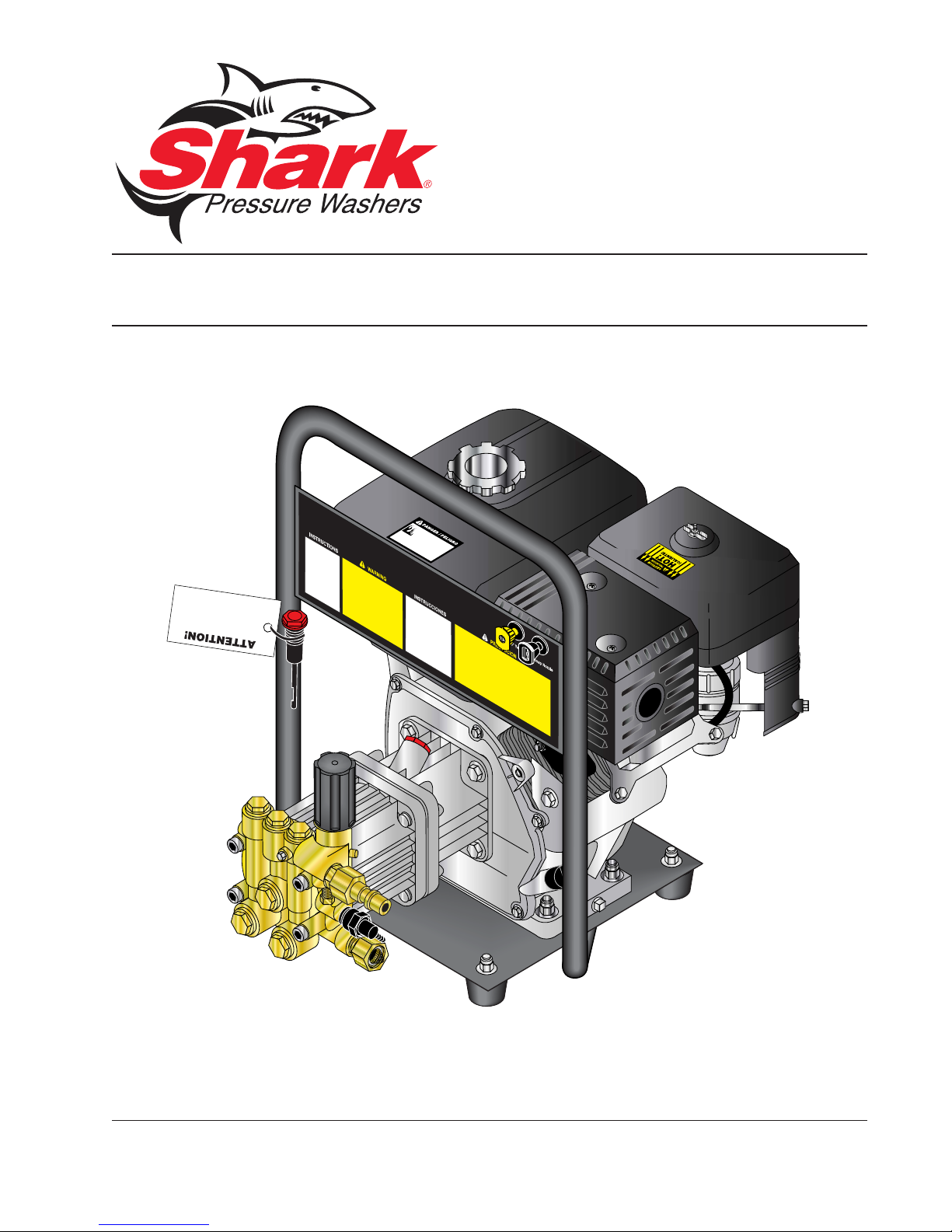
MODEL: CD
OPERATING INSTRUCTION
AND PARTS MANUAL
■ CD-2323 ■ CD-2324
For technical assistance or the SHARK dealer nearest you, call 1-800-771-1881
or visit our website at www.shark-pw .com
97-726
Page 2

Page 3

Important Safety Information................................................................4-5
Component Identification ........................................................................ 6
Assembly Instructions.............................................................................7
Operating Instructions..........................................................................8-9
Applying Detergent and General Operating Techniques........................ 10
Shut Down and Clean-Up ..................................................................... 11
Storage ................................................................................................. 11
Troubleshooting ............................................................................... 12-13
Prev entative Maintenance.....................................................................14
Oil Change Record ...............................................................................14
Exploded View ......................................................................................15
Exploded View Parts List ...................................................................... 16
Hose and Spray Gun Assembl y............................................................ 17
Warranty
CONTENTS
Model Number ______________________________
Serial Number ______________________________
Date of Purchase ___________________________
The model and serial numbers will be found on a decal attached to
the pressure washer. You should record both serial number and
date of purchase and keep in a safe place f or future reference.
3
96-719, 97-724, 97-725, 97-726 • REV. 2/04
Page 4
INTRODUCTION
Thank you for purchasing this Pressure Washer.
We reserve the right to make changes at any time with-
out incurring any obligation.
This model was designed for light use
of 1 hour per day, 5 days per week.
Owner/User Responsibility:
The owner and/or user must hav e an understanding of
PRESSURE W ASHER
the manufacturer’ s operating instructions and warnings
before using this pressure washer . W arning information
should be emphasized and understood. If the operator
is not fluent in English, the manufacturer’s instructions
and warnings shall be read to and discussed with the
operator in the operator’s native language by the purchaser/owner, making sure that the operator comprehends its contents.
Owner and/or user must study and maintain for future
reference the manufacturers’ instructions.
OPERATOR’S MANUAL
The operator must know how to stop the machine quickly
and understand the operation of all controls. Nev er permit anyone to operate the engine without proper instructions.
This manual should be considered a permanent
part of the machine and should remain with it if
machine is resold.
When ordering parts, please specify model and
serial number .
IMPORTANT SAFETY
INFORMATION
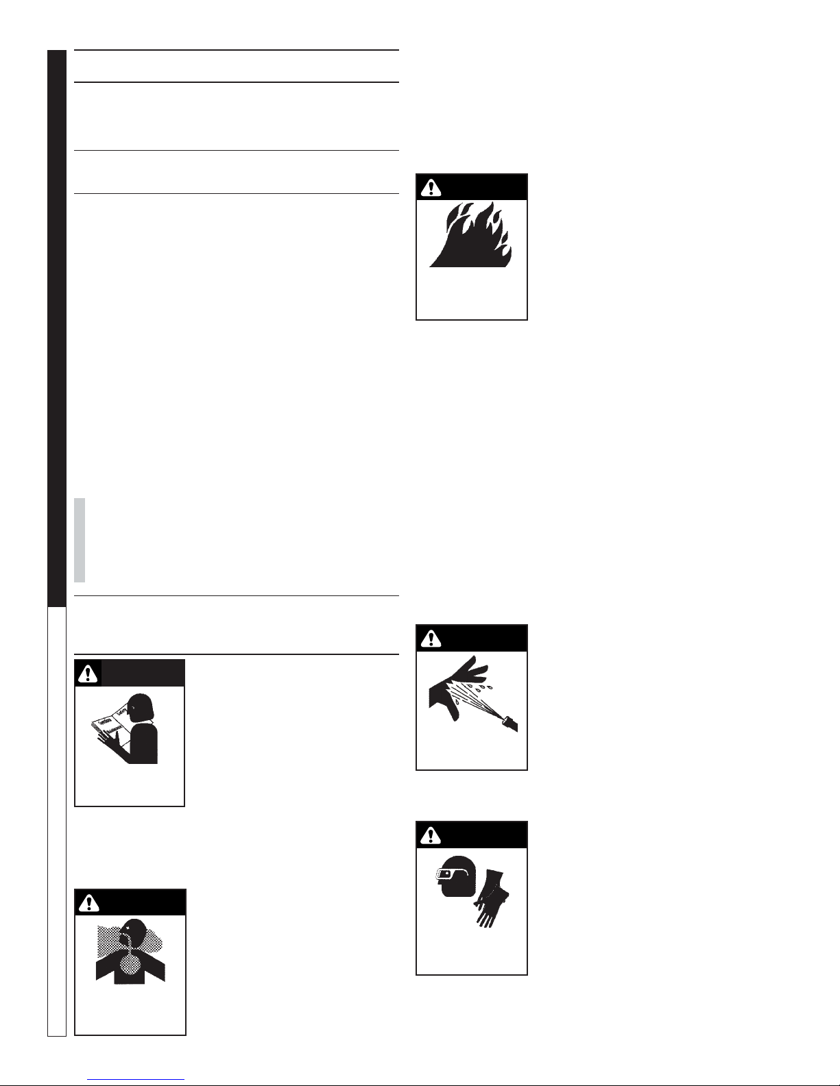
CAUTION
READ OPERATOR’S
MANUAL THOROUGHL Y
PRIOR TO USE.
2. All installations must comply with local codes. Contact your electrician, plumber, utility company or the
selling distributor for specific details.
WARNING
RISK OF
ASPHYXIATION.
USE ONLY IN A WELL
VENTILATED AREA.
4
CAUTION: To reduce the risk of
injury, read operating instructions carefully before using.
1. Read the owner's manual thoroughly. Failure to follow instructions could cause malfunction of the machine and
result in death, serious bodily
injury and/or property damage.
WARNING: Risk of asphyxiation
— Use this product only in a well
ventilated area.
3. Avoid installing machines in
small areas or near exhaust
fans. Exhaust contains poisonous carbon monoxide gas;
exposure may cause loss of
96-719, 97-724, 97-725, 97-726 • REV. 2/04
consciousness and may lead to death. It also contains detergents known, in certain quantities, to
cause cancer, birth defects or other reproductive
harm.
WARNING: Flammable liquids can create fumes which
can ignite causing property damage or severe injury.
WARNING
WARNING: Risk of fire — Do not
add fuel when the product is
operating.
WARNING: Risk of explosion —
Do not spray flammable liquids.
RISK OF FIRE.
DO NOT ADD FUEL
WHEN OPERATING
MACHINE.
4. Do not place machine near
flammable objects as the engine is hot.
5. Allow engine to cool for 2 minutes before refueling. If any fuel is spilled, make
sure the area is dry before testing the spark plug or
starting the engine. (Fire and/or explosion ma y occur if this is not done.)
When refueling gasoline engines on mobile or portable equipment, make sure to refuel:
a. outdoors;
b. with the engine on the equipment stopped;
c. with no source of ignition within 10 feet of the
dispensing point; and
d. with an allowance made for expansion of the
fuel should the equipment be exposed to a
higher ambient temperature.
In an overfilling situation, additional precautions are
necessary to ensure that the situation is handled in
a safe manner .
WARNING
WARNING: High pressure
stream of water that this equipment produces can pierce skin
and its underlying tissues, leading to serious injury and possible amputation.
HIGH PRESSURE
SPRAY CAN PIERCE
SKIN AND TISSUES.
WARNING: High pressure spray
can cause paint chips or other
particles to become airborne
and fly at high speeds. To av oid personal injury , e ye
safety devices must be worn.
WARNING
6. Eye safety devices and foot
protection must be worn when
using this equipment.
7. High pressure dev eloped by
these machines will cause personal injury or equipment
PROTECTIVE
EYE WEAR AND
CLOTHING MUST BE
WORN.
damage. Use caution when
operating. Do not direct discharge stream at people, or
severe injury or death will result.
Page 5
8. Never make adjustments on machine while in operation.
9. Do not operate with spray gun in the off position f or
extensive periods of time as this may cause damage to the pump.
10. The best insurance against an accident is precaution and knowledge of the machine.
11. Manufacturer will not be liable f or any changes made
to our standard machines, or any components not
purchased from us.
12. Read engine safety instructions provided.
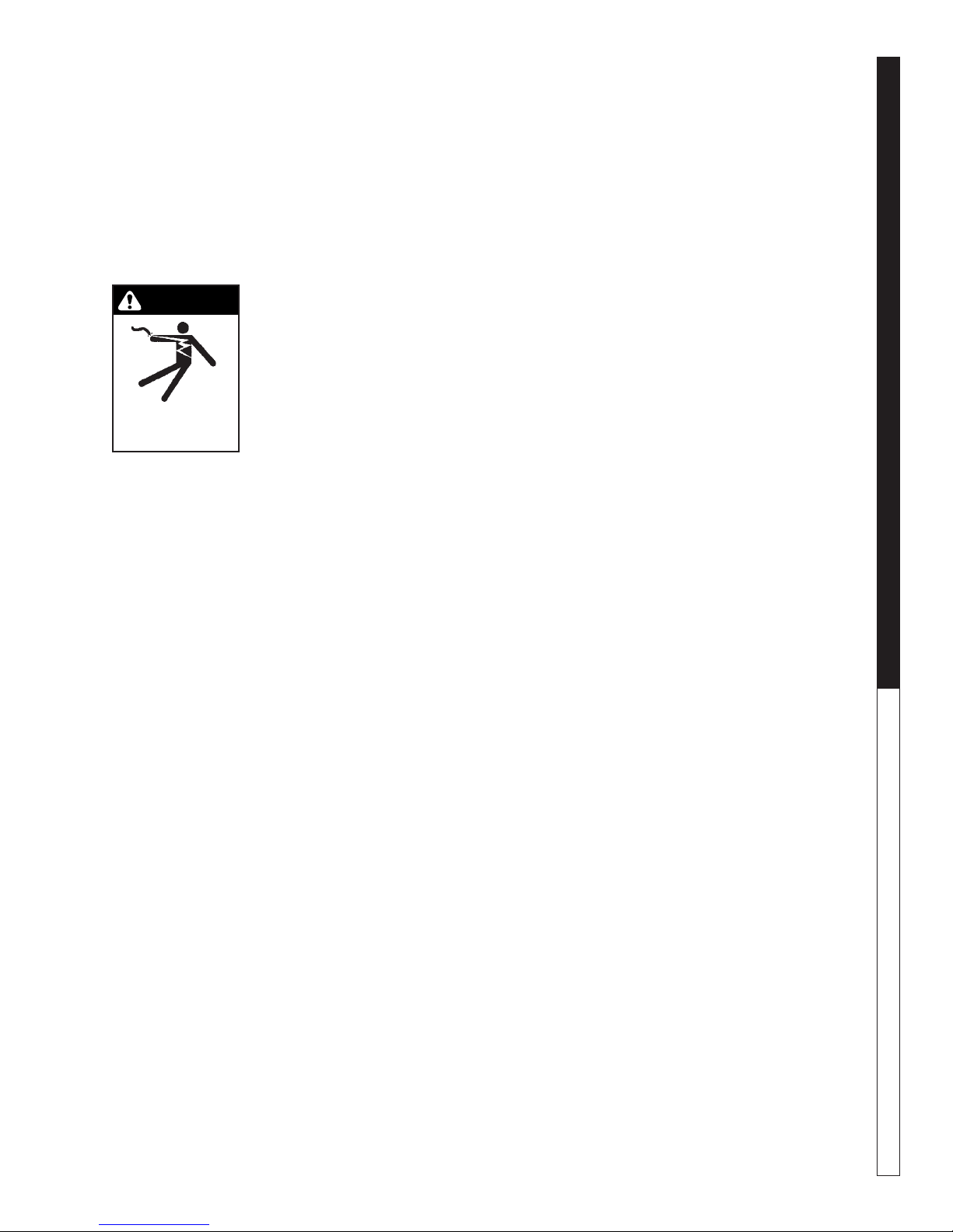
WARNING
WARNING: Keep water spray
away from electrical wiring or fatal electric shock may result.
13. Never run pump dry or leave
spray gun closed longer than
5 minutes.
KEEP WA TER SPRA Y
AWAY FROM
ELECTRICAL WIRING.
14. Do not allow children to operate the pressure washer at any
time.
15. Inlet water supply must be cold and clean fresh
water.
PRESSURE WASHER
OPERATOR’S MANUAL
5
96-719, 97-724, 97-725, 97-726 • REV. 2/04
Page 6
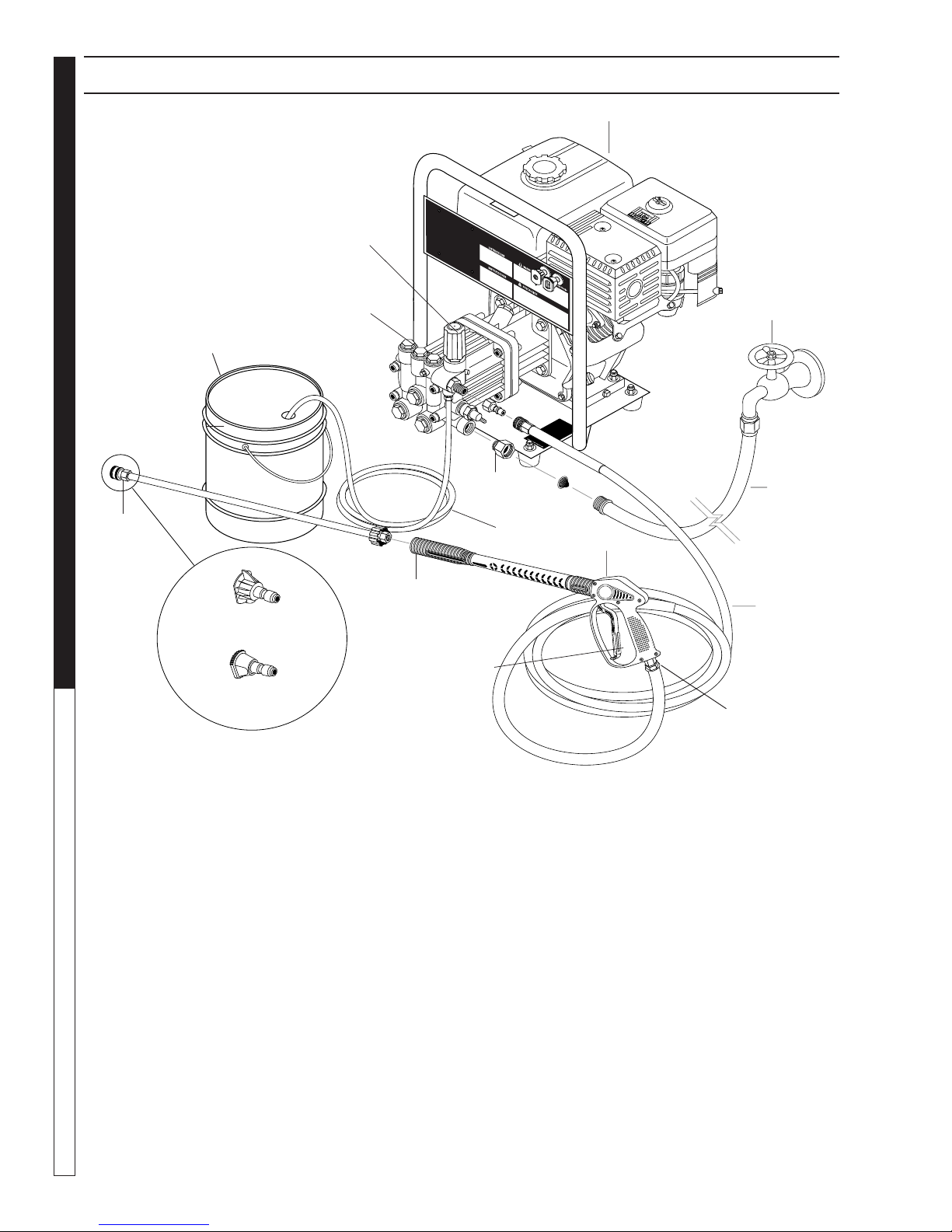
PRESSURE W ASHER
Detergent Bucket
(Not Included)
COMPONENT IDENTIFICATION
Engine
Unloader
Pump
Inlet Water
OPERATOR’S MANUAL
Quick
Coupler
Wand
High Pressure Nozzle
Soap Nozzle
Detergent Injector - Allows you to siphon and mix de-
tergents.
High Pressure Hose — Connect one end to water
pump discharge nipple and the other end to spray gun.
Nozzle Quick Coupler Pump — Dev elops high pressure.
Starter Grip — Used for starting the engine manually.
Spray Gun — Controls the application of water and
detergent onto cleaning surface with trigger device. Includes safety latch.
Inlet
Connection
Trigger
Detergent
Hose
Spray Gun
Water Supply
(Not Included)
High Pressure
Swivel
Connector
Straight Through Wand — Must be connected to the
spray gun.
Swivel Connector - Allows free range of movement to
avoid coiling hoses.
Note: If trigger on spray gun is released for more
than 2 minutes, water will leak from valve. Warm
water will discharge from pump protector onto floor .
This system prevents internal pump damage.
Hose
Hose
6
96-719, 97-724, 97-725, 97-726 • REV. 2/04
Page 7

ASSEMBLY INSTRUCTIONS
PRESSURE WASHER
Spray
Gun
Safety
Latch
High Pressure
Hose
STEP 1: Attach the high
pressure hose to the spray
STEP 2: Attach nozzle extension to spray
gun/wand. Tighten both b y hand.
gun using teflon tape on
hose threads.
Pressure
Nozzle
Wand
Coupler
Coupler
Collar
STEP 4: Release the coupler col-
lar and push the nozzle until the
collar clicks. Pull the nozzle to
make sure it is seated properly.
Nozzle
Extension
Spray Gun/
Wand
Pump
Discharge
Fitting
High
Pressure
Hose
Coupler Collar
STEP 5: Connect the high pressure
hose to the pump discharge fitting.
Push coupler collar forward until
secure.
Pressure
Nozzle
Wand
Coupler
STEP 3: Pull the spring-loaded col-
lar of the wand coupler back to insert your choice of pressure nozzle.
Cold
Water
Source
Garden
Hose
STEP 6: Connect garden hose to
the cold water source.
OPERATOR’S MANUAL
Pump
Water Inlet
Garden
Hose
STEP 7: Connect the garden hose to pump water inlet. In-
spect inlets.
CAUTION: Do not run the pump without wa-
ter or pump damage will result.
96-719, 97-724, 97-725, 97-726 • REV. 2/04
7
Page 8

PRESSURE W ASHER
OPERATING INSTRUCTIONS
Dip
Stick
Oil Dipstick
STEP 1: Check engine oil lev el. Oil le vel should be le vel with the bottom of
the oil filler neck. Be sure the machine is lev el when checking the oil le vel.
(Refer to the engine's operating manual included with machine.) We recommend that the oil be changed after the first 5 hours of use, then once
every 50 hours. Note: Improper oil levels will cause low oil sensor to shut
off engine. IMPOR T ANT! Do not run engine with high or lo w oil levels
as this will cause engine damage.
OPERATOR’S MANUAL
Gas
Tank
STEP 3: Fill gas tank with unleaded
gasoline. Do not use leaded gasoline.
Garden
Hose
STEP 4: Connect garden hose to
the cold water source and turn water on completely. Never use hot
Cold
Water
Source
water.
STEP 2: Remove shipping cap and
install oil dipstick. Check pump oil
level by using dipstick or observe
oil level in oil windo w (if equipped).
Use 30 wt. non detergent oil.
STEP 5: Trigger the s pray gun
to eliminate trapped air then wait
for a steady flow of water to
emerge from the spray nozzle.
Choke
Fuel
Valve
STEP 6: Rotate the fuel shut-off valve to the "On" posi-
tion (fully counterclockwise on Briggs engines). Slide
the fuel valve lever to the "ON" position (Honda engines). When the engine is not in use, leave the fuel
valve in the "OFF" position.
8
Choke
Lever
Fuel
Valve
STEP 7: Mov e the choke lev er to the "Choke" position
(on a warm engine, leave the choke lever in the run
position). On Honda engines , move the chok e lev er to
the "Closed" position. To restart a warm engine, leave
the choke lev er in the "Open" position.
96-719, 97-724, 97-725, 97-726 • REV. 2/04
Page 9

PRESSURE WASHER
A
G
E
L
E
S
H
A
B
OPERATING INSTRUCTIONS
E
.
E
R
N
L
.
E
I
D
O
E
L
M
A
N
U
A
L
.
On-Off
Switch
STEP 8: On Honda engines, turn the engine switch to
"On" position.
On Briggs engines, move the throttle lever to "Fast"
position, shown on engine as a rabbit.
Safety
Latch
WARNING! Never replace
nozzles without engaging the
safety latch on the spray gun
trigger.
STEP 9: Pull the starter grip. If the engine f ails to start
after 2 pulls, squeeze the trigger gun to release pressure and repeat step. Retur n starter gently. After the
engine warms up enough to run smoothly , move choke
to run position and throttle to fast position.
CAUTION: Small engines may kick back. Do not
hold pull starter grip tightly in hand.
NOZZLES
OPERATOR’S MANUAL
The two color-coded quick connect nozzles are
easily accessible when placed in the convenient rubber nozzle holder, which is provided
on the front of the machine.
NOTE: T o rinse, select the yello w . To apply detergent select the black nozzle.
9
96-719, 97-724, 97-725, 97-726 • REV. 2/04
Page 10

DETERGENTS AND GENERAL OPERATING TECHNIQUES
WARNING
PRESSURE W ASHER
OPERATOR’S MANUAL
STEP 2: Apply safety latch to spra y gun trigger. Secure
black detergent nozzle into quick coupler. NOTE: Detergent cannot be applied using the Yellow nozzle.
WARNING: Some detergents
may be harmful if inhaled or ingested, causing severe nausea,
fainting or poisoning. The harmful elements may cause property
damage or severe injury .
STEP 1: Use detergent designed
specifically for pressure washers.
Household detergents could damage the pump. Prepare detergent
solution as required by the manufacturer . Fill a container with pressure washer detergent. Place the
filter end of detergent suction tube
into the detergent container.
STEP 3: With the engine running, pull trigger to operate machine. Liquid detergent is
drawn into the machine and
mixed with water . Apply detergent to work area. Do not allow detergent to dry on surface.
pump protector engages and cools the pump by discharging the warm water onto the ground. This thermal
device prev ents internal damage to the pump .
CLEANING TIPS
Pre-rinse cleaning surface with fresh water . Place detergent
suction tube directly into cleaning solution and apply to surface at low pressure (for best results , limit your work area to
sections approximately 6 feet square and alw a ys apply detergent from bottom to top). Allow detergent to remain on
surface 1-3 minutes. Do not allow detergent to dry on surface. If surface appears to be drying, simply wet down surface with fresh water . If needed, use brush to remove stubborn dir t. Rinse at high pressure from top to bottom in an
even sweeping motion keeping the spray nozzle approximately 1 foot from cleaning surface . Use overlapping strok es
as you clean and rinse any surface. For best surface cleaning action spray at a slight angle.
Recommendations:
• Before cleaning any surf ace, an inconspicuous area
should be cleaned to test spray pattern and distance for maximum cleaning results.
• If painted surfaces are peeling or chipping, use e xtreme caution as pressure washer may remo ve the
loose paint from the surface.
• Keep the spr ay nozzle a saf e distance from the surface you plan to clean. High pressure wash a small
area, then check the surface f or damage. If no damage is found, continue to pressure washing.
CAUTION - Never use:
• Bleach, chlorine products and other corrosive
chemicals
• Liquids containing solvents (i.e., paint thinners,
gasoline, oils)
• Tri-sodium phosphate products
• Ammonia products
• Acid-based products
These chemicals will harm the machine and will damage the surface being cleaned.
RINSING
IMPORT ANT : You m ust flush the detergent injection
system after each use by placing the suction tube
into a bucket of clean water, then run the pressure
washer in low pressure for 1-2 minutes.
THERMAL PUMP PROTECTION
If you run the engine on your pressure washer for 3-5
minutes without pressing the trigger on the spray gun,
circulating water in the pump can reach high temperatures. When the water reaches this temperature, the
10
• It will take a f ew seconds f or the detergent to clear .
Apply safety latch to spray gun. Remov e black soap
nozzle from the quick coupler . Select and install the
desired high pressure nozzle. NOTE: You can also
stop detergent from flowing by simply removing detergent siphon tube from bottle.
96-719, 97-724, 97-725, 97-726 • REV. 2/04
Page 11

SHUTTING DO WN AND CLEAN-UP
On-Off
Switch
PRESSURE WASHER
STEP 1: Remove detergent suction
tube from container and insert into
one gallon of fresh water. Slide
STEP 2: Move the throttle to stop the
engine (Briggs Engine). Turn off the en-
gine (Honda engines).
nozzle forward for low pressure or
to connect black detergent nozzle.
Pull trigger on spray gun and siphon
water for one minute .
Pump
Water
Inlet
STEP 4: Press trig-
ger to release water pressure.
STEP 5: Disconnect the garden
hose from the water inlet on the
machine.
STORAGE
CAUTION: Al wa ys store y our pressure washer in a
location where the temperature will not fall below
32°F (0°C). The pump in this machine is susceptible
to permanent damage if frozen. FREEZE DAMAGE
IS NOT CO VERED BY WARRANTY.
1. Stop the pressure washer, squeeze spra y gun trigger to release pressure.
2. Detach water supply hose and high pressure hose.
3. Turn on the machine for a few seconds, until remaining water exits . T urn engine off immediately.
4. Drain the gas and oil from the engine.
5. Do not allow high pressure hose to become kinked.
6. Store the machine and accessories in a room which
does not reach freezing temperatures.
CAUTION: Failure to follo w the above directions will
result in damage to your pressure washer.
When the pressure washer is not being operated or is being
stored for more than one month, follow these instructions:
1. Replenish engine oil to upper level.
2. Drain gasoline from fuel tank, fuel line, fuel valve
and carburetor .
3. Pour about one teaspoon of engine oil through the
spark plug hole, pull the starter grip several times
and replace the plug. Then pull the starter grip slowly
96-719, 97-724, 97-725, 97-726 • REV. 2/04
STEP 3: Turn off water
supply.
High
Pressure
Outlet
STEP 6: Disconnect the high
pressure hose from high pressure outlet.
Safety
Latch
STEP 7: Engage
the spray gun
safety lock.
until you feel increased pressure which indicates
the piston is on its compression stroke and leave it
in that position. This closes both the intak e and exhaust valves to pre v ent rusting of cylinder.
4. Cover the pressure washer and store in a clean, dry
place that is well ventilated awa y from open flame or
sparks. NOTE: The use of a fuel additive, such as
STA-BIL®, or an equivalent, will minimize the formulation of fuel deposits during shortage. Such additives may be added to the gasoline in the fuel tank of
the engine, or to the gasolinee in a storage container .
After Extended Storage
CAUTION: Prior to restarting, thaw out any
possible ice from pressure washer hoses,
spray gun or wand.
Engine Maintenance
During the winter months, rare atmosheric conditions may
develop which will cause an icing condition in the carb uretor. If this develops, the engine may run rough, lose
power and may stall. This temporar y condition can be
overcome b y deflecting some of the hot air from the engine over the carburetor area. NOTE: Refer to the engine manufacturer's manual f or service and maintenance
of the engine.
OPERATOR’S MANUAL
11
Page 12

TROUBLESHOOTING
PROBLEM
LOW OPERATING
PRESSURE
FLUCTUATING
PRESSURE WASHER Troubleshooting Guide
PRESSURE
POSSIBLE CAUSE SOLUTION
Faulty pressure gauge Install new gauge.
Insufficient water supply Use larger garden hose; clean filter washer at
water inlet.
Old, worn or incorrect spray nozzle Match nozzle number to machine and/or
replace with new nozzle.
Plumbing or hose leak Check plumbing system for leaks. Retape
leaks with teflon tape.
Faulty or misadjusted unloader valve
(where applicable)
Worn packing in pump Install new packing kit.
Fouled or dirty inlet or discharge
valves in pump
Worn inlet or discharge valves Replace with valve kit.
Slow engine RPM Set engine speed per specifications
Valves worn Check and replace if necessary.
Blockage in valve Check and clean out if necessary.
Adjust unloader for proper pressure. Install
repair kit when needed.
Clean inlet and discharge valves.
(approximately 2800 RPM - 3400 RPM).
PRESSURE LOW
AFTER PERIOD OF
NORMAL USE
PUMP NOISE
Pump sucking air Check water supply and suction line for air
seepage at joints.
Worn piston packing Check and replace if necessary.
Nozzle worn Check and replace if necessary.
Inlet or discharge valves blocked or
worn
Unloader valve seat worn Check and replace if necessary.
Air suction line Check water supply and connections on
Broken or weak inlet or discharge
valve s p r ings
Foreign matter in valves Check and clean if necessary.
Worn bearings Check and replace if necessary.
Excessive temperature or liquid Reduce to below 180
Check and clean or replace if necessary.
suction line.
Check and replace if necessary.
o
F (75oC).
12
96-719, 97-724, 97-725, 97-726 • REV. 2/04
Page 13

SHUTTING DO WN AND CLEAN-UP
PRESSURE WASHER Troubleshooting Guide
PROBLEM
PRESENCE OF WATER
IN PUMP OIL
ENGINE STRAINS
UNDER LOAD
OIL SQUIRTS OUT OF
OIL CAP ON PU MP
POSSIBLE CAUSE SOLUTION
Water sprayed at machine Change oil. Direct spray away from machine.
High humidity in air Check and change oil twice as often.
Piston packing worn. Oil seal wor n Check and replace if necessary.
Engine governor misadjusted Readjust governor on engine. Take to local
engine representative for adjustment.
Incorrect spray nozzle Install proper nozzle size (See serial plate for
proper size).
Obstruction in spray nozzle Remove obstruction.
Misadjusted unloader valve
Engine low or out of oil Check oil level.
Pump low or out of oil Check oil level.
Obstruction in hose, fitting Clean or replace hose, fitting.
Pump overfilled with oil Mai ntain oil l evel at red dot on sight glass at
Call Shark technical support.
rear of pump or at top of notch on dipstick
(where applicable).
ENGINE OPERATES
FOR 15 MINUTES
THEN STOPS
WATER DRIPPING
FROM UNDER PUMP
OIL DRIPPING
EXCESSIVE VIBRATION
IN DELIVERY LINE
WATER LEAKING
FROM PUMP
PROTECTOR
Not enough gas or engine oil Fil l tank with gas. Check oil level.
Vapor lock developed by heat of day Keep gas tank full to avoi d vapor lock.
Obstruction in fuel filter Clean or replace fuel filter.
Piston packing worn Check and replace if necessary.
O-ring plunger retainer worn Check and replace if necessary.
Cracked piston Check and replace if necessary.
Oil seal worn Check and replace if necessary.
Irregular functioning of the valves Check and replace if necessary.
Spray gun closed with machine
running 5 minutes or longer.
Excessive water supply pressure Place a pressure regulator at end of 50'
Open spray gun or turn off machine.
garden hose.
13
96-719, 97-724, 97-725, 97-726 • REV. 2/04
Page 14

PREVENTATIVE MAINTENANCE
This pressure washer was produced with the best av ailable materials and quality craftsmanship. Howe ver , you as
the owner have certain responsibilities for the correct care of the equipment. Attention to regular preventative
maintenance procedures will assist in preserving the performance of your equipment. Contact your dealer for
maintenance. Regular preventativ e maintenance will add many hours to the life of y our pressure washer . P erform
maintenance more often under severe conditions .
MAINTENANCE SCHEDULE
PRESSURE W ASHER
Engine Oil
Air Cleaner/Filter
Fuel Tank Filter Every 100 hours or yearly
Spark Plug Maintenance Every 100 hours or yearly
OPERATOR’S MANUAL
Check Valve Clearance Yearly
Water Filter
Inspect Every 8 hours or daily
Change Every 50 hours or monthly
Inspect Every 8 hours or daily
Change Every 50 hours or monthly
Check Every 8 hours or daily
Clean Yearly
Inspect Every 25 hours or weekly
Pump Oil
Change Yearly
OIL CHANGE RECORD
Check pump oil and engine oil lev el bef ore first use of y our ne w pressure w asher.
Estimated Operating
Date Oil Chang ed
Month/Day/Year
Hours Since Last
Oil Change
Date Oil Chang ed
Month/Day/Year
Estimated Operating
Hours Since Last
Oil Change
14
96-719, 97-724, 97-725, 97-726 • REV. 2/04
Page 15

EXPLODED VIEW
PRESSURE WASHER
10
15
9
24
10
15
2
21
(Model 2324)
16
13
13
3
19
18
14
10
(Reversed
View)
12
15
1
22
OPERATOR’S MANUAL
11
20
11
10
10
26
25
26
27
16
10
23
4
7
6
8
11
11
10
5
5
10
17
15
96-719, 97-724, 97-725, 97-726 • REV. 2/04
Page 16

EXPLODED VIEW PARTS LIST
ITEM PART NO. DESCRIPTION QTY
1 5-0101 Engine, Honda GC1601QHA,
5 HP (232336) 1
5-0104 Engine, Honda, GX160K1QX2,
5.5 HP (232439, 232437) 1
2 5-1630 Pump, Legacy WMG-2625
(232437) 1
5-1836 Pump, Hawk HHS335CR
PRESSURE W ASHER
OPERATOR’S MANUAL
5-2102 Pump, Comet AXD 2427G
3 10-02029 Label, Danger Cool Engine 1
4 95-07200126Handle Assy (HC, TP, CD) 1
95-07102116Handle Assy (ZG) 1
5 2-01023 Mount, Vibration, 5/16”-18 x 9/16”
6 See Page 17 For Nozzle Information
7 See Page 17 For Nozzle Information
8 2-0103 Grommet, Rubber, Nozzle
9 2-1046 Plug, 1/4" Countersunk 1
10 90-4001 Washer, 5/16" Flat, SAE 16
11 90-2001 Nut, 5/16", ESNA, NC 8
12 11-0325 Label, Warning/Inst (HC) 1
11-0314 Label, Warning/Inst (TP) 1
11-0311 Label, Warning/Inst (CD) 1
10-99073 Label, Warning/Inst (ZG) 1
(232439) 1
(232336) 1
Stud, 30 Duro 4
Holder 2
ITEM PART NO. DESCRIPTION QTY
13 2-2006 Nipple, 3/8" x 3/8" NPT ST Fem1
14 11-0350F Label, French Warning 1
15 90-10074 Bolt, 5/16" x 1", NF, HH 4
16 2-300816 Pump, Protector, 3/8” PTP 1
17 90-1009 Bolt, 5/16" x 1-1/2", NC HH 4
18 95-07141120Key, Motor Shaft 1
19 4-011183 Detergent, Injector Assy
(302037, 302237, 302537) 1
20 10-9999 Label, Clear Lexan, 2-1/4" x 4" 1
21 2-10942 Swivel, 1/2" MP x 3/4" GHF
w/Strainer (2324) 1
22 10-02025A Label, "HOT CALIENTE",
w/Arrows 1
23 10-08017 Label, Intended For Outdoor
Use 1
24 5-3151 Unloader, APR.S3000 (232437)1
5-3305 Unloader, HM SS Unset
(232439) 1
25 4-02080000 Hose, 1/4” x 1/2” Clear Vinyl 4 ft.
26 2-9040 Clamp, Hose 2
27 2-1904 Strainer, Plastic 1/4” 1
16
96-719, 97-724, 97-725, 97-726 • REV. 2/04
Page 17

HOSE & SPRAY GUN ASSEMBLY
PRESSURE WASHER
5
4
6
Pressure Nozzle
7
Brass Soap
Nozzle
HOSE & SPRAY GUN ASSEMBLY PARTS LIST
ITEM PART NO. DESCRIPTION QTY
1 2-2002 Coupler, 3/8" Female 1
2-0121 ▲ Quick Coupler O-Ring 1
2 4-0203030C Hose, 30' x 3/8" w/Coupler (HC, TP
ZG) 1
4-02093450BC Hose, 3/8” x 50’, 1 Wire, Blue
(CD) 1
3 4-011137 Spray Gun, Shut-Off 1
1
OPERATOR’S MANUAL
2
3
ITEM PART NO. DESCRIPTION QTY
4 4-011106 Wand, Straight 1
5 2-2000 Coupler, 1/4” Female 1
2-0119 Quick Coupler O-Ring 1
6 4-12803015 Nozzle, 3.0 15° Yellow 1
7 4-16540 Nozzle, Brass Soap 1
▲ Not Shown
17
96-719, 97-724, 97-725, 97-726 • REV. 2/04
Page 18

Page 19

CD SERIES PRESSURE WASHER
WARRANTY
SHARK LIMITED NEW PRODUCT WARRANTY
PRESSURE WASHERS
WHA T THIS W ARRANTY COVERS
All SHARK PRESSURE WASHERS are warranted by SHARK to the original purchaser to be free from defects in materials and
workmanship under normal use, for the periods specified below . This Limited W arranty is subject to the e xclusions sho wn below ,
is calculated from the date of the original purchase, and applies to the original components only. Any parts replaced under this
warranty will assume the remainder of the part’s warranty period. This warranty applies to the original purchaser and is not
transferable.
LIMITED LIFETIME PARTS WARRANTY:
Components manufactured by SHARK, such as frames, handles, coil wraps, float tanks, and belt guards. Forged brass pump
manifold. All heating coils will have a three year warranty. Internal components on the oil-end of all pressure washer pumps will
have a seven year warranty.
ONE YEAR PARTS WARRANTY:
All other components, excluding normal wear items as described below, will be warranted for one year on parts. Warranty on
these parts will be for one year regardless of the duration of the original component manufacturer’s part warranty.
WARRANTY PROVIDED BY OTHER MANUFACTURERS:
Motors, generators, and engines, which are warranted by their respective manufacturers, are serviced through these manufacturers’ local authorized service centers. SHARK cannot provide warranty on these items.
WHAT THIS WARRANTY DOES NOT COVER
This warranty does not cover the following items:
1. Normal wear items, such as nozzles, guns, discharge hoses, wands, quick couplers, seals, filters, gaskets, O-rings,
packings, pistons, pump valve assemblies, strainers, belts, brushes, rupture disks, fuses, pump protectors.
2. Damage or malfunctions resulting from accidents, abuse, modifications, alterations, incorrect installation, improper
servicing, failure to follow manufacturer’s maintenance instructions, or use of the equipment beyond its stated usage
specifications as contained in the operator’s manual.
3. Damage due to freezing, chemical deterioration, scale buildup, rust, corrosion, or thermal expansion.
4. Damage to components from fluctuations in electrical or water supply.
5. Normal maintenance service, including adjustments, fuel system cleaning, and clearing of obstructions.
6. Transportation to service center, shop labor charges, field labor charges, or freight damage.
WHAT YOU MUST DO TO OBTAIN WARRANTY SERVICE
While not required for warranty service, we request that you register your SHARK pressure washer by returning the completed
registration card. In order to obtain warranty service on items, you must return the product to an Authorized SHARK Dealer,
freight prepaid, with proof of purchase, within the applicable warranty period. If the product is permanently installed, you must
notify your Authorized SHARK Dealer of the defect. The Authorized Dealer will file a claim, which must subsequently verify the
defect. In most cases, the part must be returned to SHARK freight prepaid with the claim. For warranty service on components
warranted by other manufacturers, the Authorized Dealer can help you obtain warranty ser vice through these manufacturers’
local authorized service centers.
LIMIT A TION OF LIABILITY
SHARK’S liability for special, incidental, or consequential damages is expressly disclaimed. In no event shall SHARK’S liability
exceed the purchase price of the product in question. SHARK makes every effort to ensure that all illustrations and specifications are correct, however, these do not imply a warranty that the product is merchantable or fit for a particular purpose, or that
the product will actually conform to the illustrations and specifications. THE WARRANTY CONTAINED HEREIN IS IN LIEU OF
ALL OTHER WARRANTIES, EXPRESS OR IMPLIED, INCLUDING ANY IMPLIED WARRANTY OF FITNESS FOR A PARTICULAR PURPOSE. SHARK does not authorize any other party , including authorized Dealers, to mak e any representation or
promise on behalf of SHARK, or to modify the terms, conditions, or limitations in any way. It is the buyer’s responsibility to ensure
that the installation and use of SHARK products conforms to local codes. While SHARK attempts to assure that its products
meet national codes, it cannot be responsible for how the customer chooses to use or install the product.
SHARK PRESSURE WASHERS
1-360-833-9100 • 1-800-771-1881 • www.shark-pw.com
PRESSURE WASHER WARRANTY
SHARK CD • 97-726 • REV. 2/04
Page 20

Form #97-726 • Revised 2/04 • Printed in U .S.A.
 Loading...