

Page 1
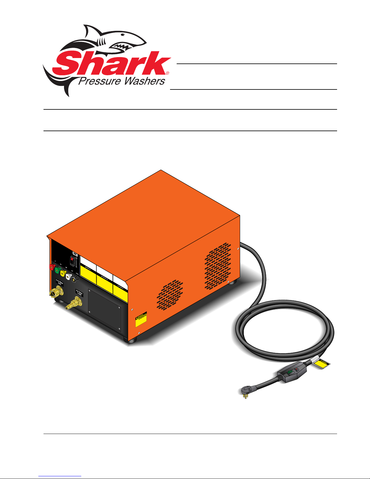
MODEL: CB
OPERATING INSTRUCTION
AND PARTS MANUAL
■ CB-3010 ■ CB-3530 ■ CB-4020
For technical assistance or the SHARK dealer nearest you, call 1-800-771-1881
or visit our website at www.shark-pw.com
#97-714
Page 2

Page 3

Important Safety Information................................................................4-5
Component Identification ........................................................................6
Assembly Instructions.............................................................................7
Operating Instructions............................................................................. 8
Applying Detergent and General Operating Techniques..........................9
Shut Down and Clean-Up ..................................................................... 10
Storage ................................................................................................. 10
Troubleshooting ............................................................................... 11-12
Prev entative Maintenance..................................................................... 13
Oil Change Record ...............................................................................13
Exploded View .................................................................................14-15
Exploded View Parts List ................................................................. 16-17
Pump Exploded Vie w and Parts List ..................................................... 18
Hose & Spray Gun Assemb ly and Parts list ..........................................19
Specifications Page .........................................................................20-21
Multi-Room Installation Guide ............................................................... 22
Warranty
CONTENTS
Model Number ______________________________
Serial Number ______________________________
Date of Purchase ___________________________
The model and serial numbers will be found on a decal attached to
the pressure washer. You should record both serial number and
date of purchase and keep in a safe place f or future reference.
3
SHARK CB • 97-714 • REV. 4/05
Page 4

INTRODUCTION
Thank you for purchasing this Pressure Washer.
All information in this manual is based on the latest prod-
uct information availab le at the time of printing.
Manufacturer reserves the right to make changes at
any time without incurring any obligation.
Owner/User Responsibility:
The owner and/or user must hav e an understanding of
the manufacturer’ s operating instructions and warnings
PRESSURE W ASHER
before using this pressure washer . W arning information
should be emphasized and understood. If the operator
is not fluent in English, the manufacturer’s instructions
and warnings shall be read to and discussed with the
operator in the operator’s native language by the purchaser/owner, making sure that the operator comprehends its contents.
Owner and/or user must study and maintain for future
reference the manufacturers’ instructions.
This manual should be considered a permanent
OPERATOR’S MANUAL
part of the machine and should remain with it if
machine is resold.
When ordering parts, please specify model and
serial number .
IMPORTANT SAFETY
INFORMATION
CAUTION
WARNING
READ OPERATOR’S
MANUAL
THOROUGHLY
PRIOR TO USE.
2. Know how to stop the machine and bleed pressure
quickly. Be thoroughly f amiliar with the controls.
3. Stay alert — watch what you are doing.
4. All installations must comply with local codes. Contact your electrician, plumber, utility company or the
selling distributor for specific details.
To comply with the National Electrical code (NFP A
70) and provide additional protection from risk of
electric shock, these pressure washers are
equipped with a UL approved ground fault circuit
interrupter (GFCI) power cord.
4
CAUTION: T o reduce the risk of
injury, read operating instructions carefully before using.
1. Read the owner's manual thoroughly. Failure to follow instructions could cause malfunction of the machine and
result in death, serious bodily
injury and/or property damage.
SHARK CB • 97-714 • REV. 4/05
WARNING
WARNING: Flammable liquids
can create fumes which can ignite causing property damage or
severe injury .
WARNING: Risk of explosion —
RISK OF EXPLOSION:
DO NOT USE WITH
FLAMMABLE
LIQUIDS.
do not spray flammable liquids.
Risk of explosion — do not spray
flammable liquids or operate in
an explosive location.
WARNING
WARNING: Keep water spray
away fr om electrical wiring or fatal electric shock may result.
5. To protect the operator from
electrical shock, the machine
must be electrically grounded.
KEEP WATER SPRAY
AWAY FROM
ELECTRICAL WIRING.
It is the responsibility of the
owner to connect this machine
to an approved grounded
receptacle of proper voltage and amperage ratings.
Do not spray water on or near electrical components. Do not touch machine with wet hands or while
standing in water . Always disconnect po wer before
servicing.
6. Grip cleaning wand securely with both hands before starting. F ailure to do this could result in injury
from a whipping wand.
WARNING
WARNING: High pressure stream
of fluid that this equipment can
produce can pierce skin and its
underlying tissues, leading to serious injury and possible amputation.
HIGH PRESSURE
STREAM CAN
PIERCE SKIN AND
TISSUES.
7. High pressure developed by
these machines will cause
personal injury or equipment
damage. Use caution when operating. Do not direct discharge stream at people, or severe injury or
death will result.
8. Never make adjustments on machine while in operation.
WARNING
WARNING: High pressure spray
can cause paint chips or other
particles to become airborne and
fly at high speeds.
9. Eye safety devices, hand and
USE PROTECTIVE
EYEWEAR
WHEN OPERA TING
EQUIPMENT.
foot protection must be worn
when using this equipment.
10. When the machine is working,
do not cover or place in a closed space where ventilation is insufficient.
11. Protect from freezing.
12. Be certain all quick coupler fittings are secured before using pressure washer .
13. Do not allow acids, caustic or abrasive fluids to pass
through the pump.
Page 5

14. Inlet water must be no hotter then 190° and clean
fresh water . It is recommended that inlet water temperatures not exceed 175° f or pump longe vity.
15. The best insurance against an accident is precaution and knowledge of the machine.
16. Manufacturer will not be liable for an y changes made
to our standard machines or any components not
purchased from them.
17. T o reduce the risk of injury , close supervision is necessary when a machine is used near children. Do
not allow children to operate the pressure washer .
This machine must be attended during operation.
18. Do not operate this machine when fatigued or under the influence of alcohol or drugs.
19. K eep operating area clear of all persons .
20. Do not overreach or stand on unstable support.
Keep good footing and balance at all times .
21. Follow the maintenance instructions specified in the
manual.
PRESSURE WASHER
OPERATOR’S MANUAL
5
SHARK CB • 97-714 • REV. 4/05
Page 6
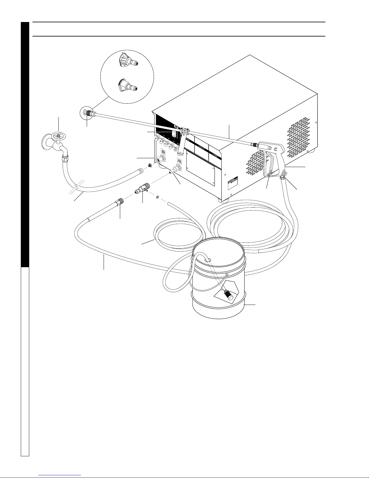
COMPONENT IDENTIFICATION
High Pressure
Nozzle
Soap Nozzle
PRESSURE W ASHER
Supply
OPERATOR’S MANUAL
Water
Coupler
Garden Hose
(not included)
Quick
Garden Hose Inlet
High Pressure
Hose
On/Off
Switch
Detergent
Hose
Coupler
Detergent
Pick-up T ube
Injector
Discharge
Nipple
Wand
Trigger
Spray
Gun
Swivel
Connector
Detergent Injector - Allows you to siphon and mix de-
tergents, when used with soap nozzle.
High Pressure Hose — Connect one end to water
pump discharge nipple and the other end to spray gun.
Spray Gun — Controls the application of water and
detergent onto cleaning surface with trigger device. Includes safety latch.
6
Detergent Bucket
(not included)
Wand — Must be connected to the spra y gun.
Swivel Connector - Allows free range of movement to
avoid coiling hoses.
Note: If trigger on spray gun is released for more
than 2 minutes, water will leak from pump protector valve. Warm water will discharge onto floor and
cool water will allow the pump protector to seal.
This system prevents internal pump damage.
SHARK CB • 97-714 • REV. 4/05
Page 7
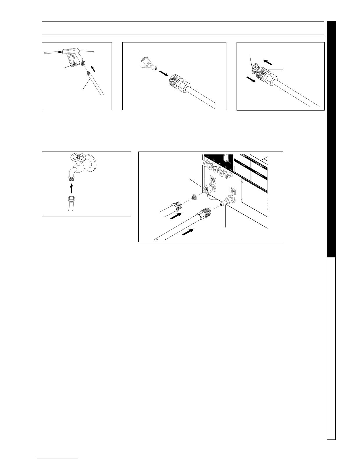
ASSEMBLY INSTRUCTIONS
PRESSURE WASHER
Spray
Gun
Safety
Latch
High Pressure
Hose
STEP 1: Attach the high pres-
sure hose to the spray gun
using teflon tape on hose
threads. Use safety latch to
prevent from opening.
STEP 2: Insert nozzle into coupler.
Inlet
Fitting
Nozzle
Coupler
STEP 3: Release the coupler col-
lar and push the nozzle until the
collar clicks. Pull the nozzle to make
sure it is seated properly .
OPERATOR’S MANUAL
STEP 4: Connect garden hose to
the cold water source.
Outlet Fitting
STEP 5: Connect the high pressure hose to the outlet dis-
charge fitting. Push coupler collar forward until secure.
Connect the garden hose to pump water inlet. Inspect inlets. CA UTION: Do not run the pump without water or
pump damage will result.
7
SHARK CB • 97-714 • REV. 4/05
Page 8
PRESSURE W ASHER
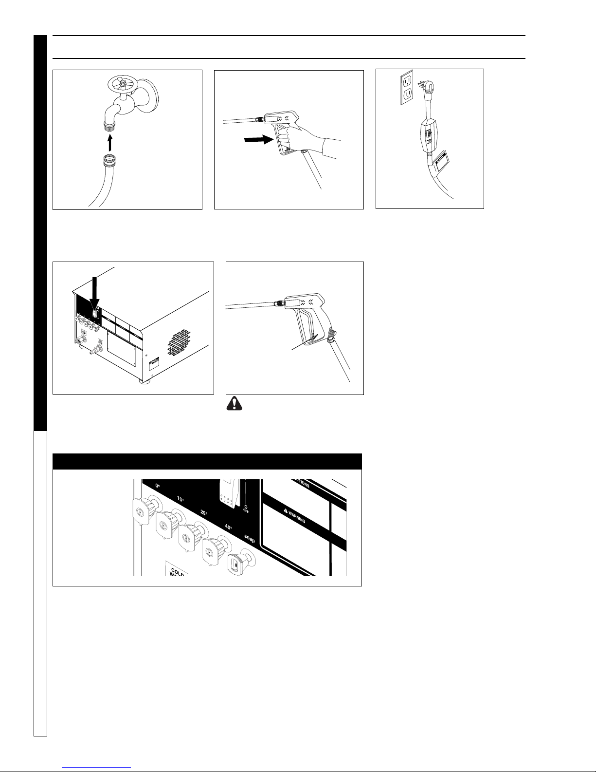
OPERATING INSTRUCTIONS
Cold
Water
Source
Garden
Hose
STEP 1: Connect garden hose to the
cold water source and turn water on
completely. Nev er use hot w ater.
OPERATOR’S MANUAL
STEP 4: Turn machine on by pushing
switch at front of machine.
NOZZLES
STEP 2: Trigger the spray gun to
eliminate trapped air then wait f or
a steady flow of water to emerge
from the spray nozzle.
Safety
Latch
WARNING! Never replace
nozzles without engaging the
safety latch on the spray gun
trigger.
STEP 3: Connect to ap-
propriate power supply.
Push GFCI reset button.
The five color-coded quick connect nozzles provide a wide arra y of spr a y
widths from 0° to 45° and are easily accessible when placed in the convenient rubber nozzle holder, which is provided on the front of the machine .
NOTE: F or a more gentle rinse, select the white 40° or green 25° nozzle.
T o scour the surf ace, select the yellow 15° or red 0° nozzle . To apply detergent select the black nozzle.
8
SHARK CB • 97-714 • REV. 4/05
Page 9

DETERGENTS AND GENERAL OPERATING TECHNIQUES
PRESSURE WASHER
WARNING
STEP 2: Apply safety latch to spra y gun trigger. Secure
black detergent nozzle into quick coupler. NOTE: De-
tergent cannot be applied using the Yellow nozzle.
IMPORT ANT : You m ust flush the detergent injection
system after each use by placing the suction tube
into a bucket of clean water, then run the pressure
washer in low pressure for 1-2 minutes.
WARNING: Some detergents
may be harmful if inhaled or ingested, causing severe nausea,
fainting or poisoning. The harmful elements may cause property
damage or severe injury .
STEP 1: Use detergent designed
specifically for pressure washers.
Household detergents could damage the pump. Prepare detergent
solution as required by the manufacturer . Fill a container with pressure washer detergent. Place the
filter end of detergent suction tube
into the detergent container.
STEP 3: With the motor running, pull trigger to operate machine. Liquid detergent is
drawn into the machine and
mixed with water . Apply detergent to work area. Do not allow detergent to dry on surface.
THERMAL PUMP PROTECTION
water reaches this temperature, the pump protector
engages and cools the pump by discharging the warm
water onto the ground. This thermal device pre vents internal damage to the pump.
CLEANING TIPS
Pre-rinse cleaning surface with fresh water. Place detergent suction tube directly into cleaning solution and
apply to surface at low pressure (for best results, limit
your work area to sections approximately 6 f eet square
and always apply detergent from bottom to top). Allow
detergent to remain on surface 1-3 minutes. Do not allow detergent to dry on surface. If surface appears to
be drying, simply wet down surface with fresh water. If
needed, use brush to remove stubborn dirt. Rinse at
high pressure from top to bottom in an even sweeping
motion keeping the spray nozzle approximately 1 foot
from cleaning surface. Use overlapping strokes as you
clean and rinse any surface. For best surface cleaning
action spray at a slight angle.
Recommendations:
• Before cleaning any surface, an inconspicuous
area should be cleaned to test spray pattern and
distance for maximum cleaning results.
• If painted surfaces are peeling or chipping, use
extreme caution as pressure washer ma y remove
the loose paint from the surface.
• Keep the spray nozzle a safe distance from the
surface you plan to clean. High pressure wash a
small area, then check the surface for damage. If
no damage is found, continue to pressure washing.
CAUTION - Never use:
• Bleach, chlorine products and other corrosive
chemicals
• Liquids containing solvents (i.e., paint thinners,
gasoline, oils)
• Tri-sodium phosphate products
• Ammonia products
• Acid-based products
These chemicals will harm the machine and will damage the surface being cleaned.
RINSING
• It will take a few seconds f or the detergent to clear .
Apply safety latch to spray gun. Remov e black soap
nozzle from the quick coupler . Select and install the
desired high pressure nozzle. NOTE: You can also
stop detergent from flowing by simply removing detergent siphon tube from bottle.
OPERATOR’S MANUAL
If you run your pressure washer f or 3-5 minutes without
pressing the trigger on the spray gun, circulating water
in the pump can reach high temperatures. When the
9
SHARK CB • 97-714 • REV. 4/05
Page 10

SHUTTING DO WN AND CLEAN-UP
PRESSURE W ASHER
STEP 1: Remove detergent suction tube
STEP 2: Turn off machine by
pushing switch on front panel.
from soap container
and insert into one
gallon of fresh water.
Use black soap nozzle
with detergent injector.
Pull trigger on spray
gun and siphon water
for one minute.
OPERATOR’S MANUAL
Pump
Water
Inlet
STEP 5: Disconnect the garden
hose from the water inlet on the
machine. Protect from freezing.
STEP 3: Turn off water supply .
High
Pressure
Outlet
STEP 6: Disconnect the high
pressure hose from high pressure outlet.
STEP 4: Press trigger
to release water pressure.
Safety
Latch
STEP 7: Engage
the spray gun
safety lock.
Pump Storage
CAUTION: Always store your pressure washer in a location where the
temperature will not fall below 32° F
(0° C). The pump in this machine is
CAUTION
If you must store your pressure washer in a location
where the temperature is below 32° F, you can minimize the chance of damage to your machine by draining your machine as follo ws:
1. Stop the pressure washer and detach supply hose
and high pressure hose. Squeez e the trigger of the
spray gun to drain all water from the wand and
hose.
2. Restart pressure washer and let it run briefly (about
5 seconds) until water no longer discharges from
10
the high pressure outlet.
susceptible to permanent damage if
frozen.
FREEZE DAMA GE IS NOT CO VERED
BY WARRANTY .
SHARK CB • 97-714 • REV. 4/05
STORAGE
Page 11

TROUBLESHOOTING
PROBLEM POSSIBLE CAUSE SOLUTION
PRESSURE WASHER Troubleshooting Guide
PUMP RUNNING
NORMALLY BUT
PRESSURE LOW ON
INST ALLATION
FLUCTU ATING
PRESSURE
PRESSURE LOW
AFTER PERIOD
OF NORMAL USE
Pump sucking air Check water supply and possibility of air
seepage.
Check valves sticking Check and clean or replace if necessary.
Unloader valve seat faulty Check and replace if necessary.
Nozzle incorrectlly sized Check and replace if necessary.
Worn piston packing Check and replace if necessary.
Valves worn Check and replace if necessary.
Blockage in valve Check and clean out if necessary.
Pump sucking air Check water supply connections.
Worn piston packing Check and replace if necessary.
Insufficient water Check filter and hose for breakage.
Nozzle worn Check and replace if necessary.
Suction or delivery valves worn Check and replace if necessary.
Suction or delivery valves blocked Check and clean if necessary.
PUMP NOISY
Unloader valve seat worn Check and replace if necessary.
Unloader adjusted improperly Call local Landa dealer.
Worn piston packing Check and replace if necessary.
Bypass valve within unloader is
obstructed or leaking
Air in suction line Check water supply and connections on suction
Broken or weak suction or delivery
valve spring
Foreign matter in valves Check and clean if necessary.
Worn bearings Check and replace if necessary.
Excessive temperature of water Reduce to below 140
Remove and clean bypass cartridge.
line.
Check and replace if necessary.
o
F.
11
SHARK CB • 97-714 • REV. 4/05
Page 12

TROUBLESHOOTING
PROBLEM POSSIBLE CAUSE SOLUTION
PRESENCE OF WATER
IN PUMP OIL
WAT E R DRI PPING
FROM UNDER PUMP
OIL DRIPPING FROM
PUMP
EXCESSIVE VIB RATION
IN HIGH PRESSURE
HOSE
MOTOR WILL NOT RUN
PRESSURE WASHER Troubleshooting Guide
MACHINE WILL NOT
TURN ON WHEN
SWITCH IS PU SH ED
Oil seal worn Check and replace if necessary.
High humidity in air Check and change oil twice as often.
Piston packing worn Check and replace if necessary.
Piston packing worn Check and replace if necessary.
O-Ring plunger retainer worn Check and replace if necessary.
Oil seal worn Check and replace if necessary.
Irregular functioning of the pump
valves
Obstruction in filter Clean inlet filter.
Motor overload Push in the overload button located on the
Stepdown transformer fuses Check fuses and voltage. Replace if necessary.
Coil of magnetic starter defective Replace coil after the timer and unloader switch
Timer is defective Join wires 15 and 16 together on timer. If
Check and replace if necessary.
motor (single phase) or the overload button on
the magnetic start switch (three phase).
have been tested.
works, replace timer.
12
SHARK CB • 97-714 • REV. 4/05
Page 13

PREVENTATIVE MAINTENANCE
PREVENTATIVE MAINTENANCE
This pressure washer was produced with the best av ailable materials and quality craftsmanship. Howe ver , you as
the owner, have certain responsibilities for the correct care of the equipment. Attention to regular preventative
maintenance procedure will assist in preserving the performance of your equipment. Contact your dealer for
maintenance. Regular preventativ e maintenance will add many hours to the life of y our pressure washer . P erform
maintenance more often under severe conditions .
MAINTENANCE SCHEDULE
Inspect 25 Hours or Weekly
Pump Oil
Change Yearly
PRESSURE WASHER Troubleshooting Guide
Check Valve Clearance
Inspect Every 6 Hours or Dail y
Water Filter
Clean Yearly
Yearly
OIL CHANGE RECORD
Check pump oil lev el before first use. Change pump oil after first 50 hours and e very month or 500 hours thereafter.
Use SAE 30 weight oil.
Date Oil Changed
Month/Day/Year
Estimated Operating
Hours Since Last
Oil Change
Date Oil Changed
Month/Day/Year
Estimated Operating
Hours Since Last
Oil Change
13
SHARK CB • 97-714 • REV. 4/05
Page 14

PRESSURE W ASHER
76
20
EXPLODED VIEW
10
Enlarged
Reverse View
64
63
63
70
62
78
9
7
74
13
71
OPERATOR’S MANUAL
Time Delay
Option
Auto Start
Option
7
64
76
75
Auto Start
Option
77
64
9
75
3010D w/Time
Delay Option
77
64
61
74
70
63
22
64
13
58
61
5
6
62
62
66
71
12
25
21
4
51
19
58
24
12
22
25
1
54
23
58
3
For
Detail
SeePump
Assy.
2
11
14
15
8
23
SHARK CB • 97-714 • REV. 4/05
14
Page 15

EXPLODED VIEW
27
39
PRESSURE WASHER
OPERATOR’S MANUAL
53
32
29
46
17
37
31
33
65
42
73
50
67
38
44
40
16
41
43
60
59
46
68
50
26
28
45
49
69
72
57
56
59
30
47
55
35
36
34
18
SHARK CB • 97-714 • REV. 4/05
52
46
19
48
50
15
Page 16

EXPLODED VIEW PARTS LIST
ITEM PART NO. DESCRIPTION QTY
1 Unloader, See Specifications pages 20-21
2 Pump, See Specifications pages 20-21
3 Motor, See Specifications pages 20-21
4 Transformer, See Specifications pages 20-21
5 6-02294 Fuse, ATMR, 1 Amp, 600V
(3530A, B; 4020A, B) 2
PRESSURE W ASHER
OPERATOR’S MANUAL
16
6-02295 Fuse, 1/2 Amp, 600V (3530C,
4020C) 2
6 6-022970 Fuse, Paper, Buss FNM-1/2,
250V Midget (3530, 4020) 1
7 Contactor, See Specification pages 20-21
8 2-1105 Swivel, 1/2" JIC Fem,
Push-On 2
9 6-021595 Din Rail, 35 mm 4"
10 6-03909 Box, Plastic, 10" x 8" x 6"
w/Lid (4020, 3530) 1
6-03907 Box, Plastic 8" x 8" x 4",
(3010) 1
11 95-07603907 Bracket, Electric Box
Support 1
12 6-05153 Strain Relief, STRT, LQ Tite
(3010) 1
6-05181 ▲ Locknut, 1/2" Conduit 1
6-051595 Strain Relief, STRT, LQ Tite
(3530A, B, C, G, H;4020A, B,
C, G, H) 1
6-05172 ▲ Lock Nut, 3/4”
(3530A, B, C, G, H;4020A, B,
C, G, H) 1
13 6-05153 Strain Relief, STRT, Med. 1
6-05181 Locknut, 1/2" Conduit 1
14 4-02047720 Hose, 3/8" x 20", 2 Wire,
Pressure Loop (4020, 3530)1
4-02047725 Hose, 3/8” x 25”, 2 Wire,
Pressure Loop (3010) 1
15 4-02110000 Hose, 1/2" Push-On 1 ft.
16 90-2001 Nut, 5/16” ESNA 4
17 95-0710375546 Slider, Pump 1
18 90-1027461 Bolt, 1/2” x 8” 1
19 90-4001 Washer, 5/16", Flat, SAE
(3010) 4
90-4002 Washer, 3/8” SAE, Flat (3530,
4020) 4
20 Overload, See Specifications Pages 20-21
21 95-07290068 Standoff, Electrical Box (3530,
4020) 1
22 6-051595 Strain Relief, 3/4" Strt, LQ Tite
(3530B, C, H;4020 A, B, C, G,
H) 1
6-05172 ▲ Lock-Nut, 3/4” (3530B, C, H;
4020A, B, C, G, H) 1
6-05153 Strain Relief, Strt, LQ Tite
(3010) 1
SHARK CB • 97-714 • REV. 4/05
ITEM PART NO. DESCRIPTION QTY
22 6-05181 ▲ Lock Nut, 1/2” Conduit
(3010) 1
6-05170 Strain Relief, 3/4” (3530A,
G) 1
6-05172 ▲ Lock-Nut, 3/4” (3530A, G)1
23 2-08018 Label, Warn Service Cord 1
24 2-0053 Elbow, 1/2" JIC x 3/8" 90° 1
25 6-0108 Cord, Serv, SEO, 10/3 Coleman,
Motor (4020A,G) 3.33 ft.
6-0109 Cord Service, 10/4, Motor
(3530H) 3.33 ft.
6-01041 Cord, Ser vice, 12/3, Motor
(3010D) 4.25 ft.
6-0102 Cord, Service, 8/3, Motor
(3530A,G) 3.33 ft.
6-0105 Cord Service, 12/4, Motor
(4020B,C,H;3530B,C) 3.33 ft.
26 10-08021 Label, Disconnect Power
Supply 1
27 95-07102129 Cover, Cabinet, Cold Water 1
28 95-07102122 Base Cabinet, Cold Water,
Wrinkle Black 1
29 6-020240 Switch, Rocker, Carling
w/Green Lens 1
6-020241 Switch, Rocker, Carling Red
(Time-Delay Shutdown
Option) 1
30 2-01041 Pad, Soft Rubber, Duro 50 4
31 2-0103 Grommet, Rubber
(Nozzle Holder) 5
32 2-10942 Swivel, 1/2" MP x 3/4"
GHF w/strainer 1
33 2-11041 Connector, 1/2" Anchor 1
34 2-11039 Connector, 3/8" Anchor 1
35 4-011184 Downstream Injector Assembly,
Non-Adj. 1
36 2-2007 Nipple, 3/8" x 3/8" NPT ST
Male 1
37 4-12806000 Nozzle, 0006, Red (4020) 1
4-12806015 Nozzle, 1506, Yellow (4020)1
4-12806025 Nozzle, 2506, Green (4020) 1
4-12806040 Nozzle, 4006, White (4020) 1
4-12804000 Nozzle, 0004, Red (3530) 1
4-12804015 Nozzle, 1504, Yellow (3530)1
4-12804025 Nozzle, 2504, Green (3530) 1
4-12804040 Nozzle, 4004, White (3530) 1
4-12805500 Nozzle, 0005.5, Red (3010)1
4-12805515 Nozzle, 1505.5, Yellow
(3010) 1
4-12805525 Nozzle, 2505.5, Green
(3010) 1
4-12805540 Nozzle, 4005.5, White
(3010) 1
Page 17

EXPLODED VIEW PARTS LIST
PRESSURE WASHER
ITEM PART NO. DESCRIPTION QTY
38 11-0308 Label, Control Panel (CB
Models) 1
39 11-0601 Label, Str ipe, 29” (CB) 2
40 Bushing, See Specifications pages 20-21
41 Bushing, See Specifications pages 20-21
42 Pump Pulley, See Specifications pages 20-21
43 Motor Pulley, See Specifications pages 20-21
44 Belt, See Specifications pages 20-21
45 6-05171 Strain Relief, 1" 1
46 90-1995 Screw, 1/4" x 1/2", BH SOC
CS 14
47 90-40125 Washer, 3/8" x 1" Steel 4
48 90-1007 Bolt, 5/16” x 1 NC (3010) 4
90-1016 Bolt, 3/8” x 1” NC, HH (3530,
4020) 4
49 10-9999 Label, Clear Lexan,
2-1/4" x 4-1/2" 1
50 2-01107 Weather Stripping 7 ft.
51 90-2002 Nut, 3/8" ESNA, NC
(3530, 4020) 4
90-2001 Nut, 5/16", ESNA, NC
(3010) 4
52 90-3096 Washer, 1/2” Flat 1
53 95-07102289 Cover, Access Hole 1
54 90-2000 Nut, 1/4", ESNA NC 2
55 90-1018 Bolt, 3/8" x 1-1/2", NC HH 4
56 2-0108 Bumper Pad, Engine 4
57 90-4007 Washer, 3/8" x 1-1/2"
Fender 4
58 6-01060 GFCI, 120V 20A w/36'
12-3 Cord (3010D) 1
6-01059 GFCI, 240V 1Ph, 30A, 36'
10-3 Cord (4020A,G) 1
6-010690 GFCI 240V 1Ph 40A, 36'
8-3 Cord (3530A,G) 1
6-0105 Cord, Serv, SEO 12/4
(4020B,C,H;3530B,C) 10 ft.
6-0109 Cord, Service, 10/4 (3530H)10 ft.
ITEM PART NO. DESCRIPTION QTY
59 90-20231 Nut, Cage, 1/4" x 12 Gauge 8
60 2-0114 Nut, 1/4" Square Head
Grommet, Nylon 4
61 11-1042 Label, Ground 1
62 90-1994 Screw, 10/32" x 1-1/4" RH,
SL (3530, 4020) 1
(3010) 2
63 90-1991 Screw, 10/32" x 1/2" BHSOC
(3530, 4020) 11
64 90-017 Nut, 10/32" KEPS (3010) 4
(3530, 4020) 10
65 10-09003 Label, Cold Water Inlet, HS 1
66 6-051532 Strain Relief, 3/4", LQ Tite
(3010) 1
6-051595 Strain Relief, STRT, LQ Tite
(3530B,C;4020A,B,C,G,H) 1
6-05181B ▲ Locknut, 3/4” (3010; 3530B,C;
4020A,B,C,G,H) 1
6-051700 Strain Relief, 1”
(3530A,G,H) 1
6-05182 ▲ Locknut, 1” (3530A,G,H) 1
67 10-09002 Label, Cold Water Outlet 1
68 10-02028 Label, Warning, Exposed
Pulleys 1
69 10-08016 Label, Intended for Indoor
Use 1
70 6-05152 Strain Relief, Small, LQ Tite
(Time Delay/Auto-Start
Option) 1
6-05181 ▲ Lock-Nut, 1/2” Conduit
(Time Delay/Auto-Start
Option) 1
71 6-0101 Cord, Service, SEO, 16/3 2.5 ft.
6-01011 Cord, Service, SEO 16/4 (Time
Delay Shutdown Option) 2.5 ft.
72 90-2002 Nut, 3/8” ESNA 4
73 90-4001 Washer, 5/16” Flat 4
74 6-03541 Base Relay (Time
Delay Shutdown Option) 1
75 6-03621 Relay (Time Delay Shutdown
Option) 1
76 6-03700 Timer, Multi-Function, 24V-120/
240V (Time Delay Shutdown
Option) 1
77 6-036880 Timer, Solid State, 120V,
5-60 Mins, Adjustable (Auto
Start/Stop Option) 1
78 90-2018 Nut, Cage, 10/32” x 16 Gauge
(3530, 4020) 6
▲ Not Shown
OPERATOR’S MANUAL
17
SHARK CB • 97-714 • REV. 4/05
Page 18

PUMP EXPLODED VIEW
2
PRESSURE W ASHER
OPERATOR’S MANUAL
16
17
12
14
13
1
3
2
4
8
Auto
Start/Stop
15
3
Option
4
6
5
10
9
Time
Delay
Shutdown
Option
11
PUMP EXPLODED VIEW PARTS LIST
ITEM PART NO. DESCRIPTION QTY
1 Unloader, See Specifications Pages 20-21
2 2-0053 Elbow, 1/2" JIC, 3/8", 90° 2
(Auto Start/Stop Option) 1
3 2-0079 Swivel, 1/2" JIC x 3/8" Male 1
4 2-1060 Elbow, 1/2 "JIC x 3/8" 1
5 2-1006 Nipple, 1/2" Close 1
6 2-1032 Tee, 1/2" Female Pipe 1
7 2-1053 Nipple, 1/2" JIC x1/2" MPT
Pipe 1
ITEM PART NO. DESCRIPTION QTY
8 2-1062 Elbow, 1/2" JIC x 1/2", 90° 1
9 2-1105 Swivel Push-On, 1/2" JIC
Female 2
10 4-02110000 Hose, 1/2" Push-On 18"
11 2-3008150 Protector, Pump, 1/2", 190° 1
12 Pump, See Specifications pages 20-21
13 70-460146 Cap, Valve w/1/4” Gauge
Port (Time Delay Shutdown
Option) 1
14 6-021720 Switch, Pressure, N/O, 1/4” NP
(Time Delay Shutdown
Option) 1
15 2-00510 Nipple, 1/2” JIC x 3/8” Female
(Auto Start/Stop Option) 1
16 5-3027 Unloader, PA 8 GPM@3650 PSI,
VB8, w/Switch (Auto Start/Stop
Option) 1
17 2-0031 Elbow, 3/8” Street (Auto Start/
Stop Option) 2
18
SHARK CB • 97-714 • REV. 4/05
Page 19

PRESSURE WASHER
HOSE & SPRAY GUN ASSEMBLY
6
5
4
8
OPERATOR’S MANUAL
3
7
1
11
10
9
HOSE & SPRAY GUN ASSEMBLY PARTS LIST
ITEM PART NO. DESCRIPTION QTY
1 2-2002 Coupler, 3/8” Female 1
2-0121 Quick Coupler O-Ring 1
2 4-02093450BC Hose 3/8” x 50’, 1 Wire Blue
w/Coupler (CB) 1
3 4-01246 Spray Gun 1
4 4-0110322 Wand w/Side grip 1
5 4-16540 Nozzle, Soap, Brass 1
6 Nozzle, See Exploded View Parts List
2
ITEM PART NO. DESCRIPTION QTY
7 3-12021 Injector, Chemical Adj.,
3-5 GPM 0.083 1
8 2-2000 Coupler, 1/4” Female 1
2-0119 Quick Coupler O-Ring 1
9 4-02080000 Tube, 1/4” x 1/2” Clear Vinyl 6 ft.
10 2-9040 Clamp, Hose 2
11 2-1904 Strainer 1
19
SHARK CB • 97-714 • REV. 4/05
Page 20

SPECIFICATIONS
Nozzle Pump Unloader Pump Pump Pulley Pump Bushing Motor Motor Motor
Model Size Pump Part No. Part No. Pulley Part No. Bushing Part No. Size Voltage/ph Hz
301001D 5.5 T991 5-23020 5-3208 AK74H 5-40107401 24MM 5-512024 2HP 120V/1PH 60
402007A 06 GM4035HR 5-1922 5-3208 2AK74H 5-40207401 24MM 5-512024 6.2HP 230V/1PH 60
402007B 06 GM4035HR 5-1922 5-3208 2AK74H 5-40207401 24MM 5-512024 6.2HP 230V/3PH 60
402007C 06 GM4035HR 5-1922 5-3208 2AK74H 5-40207401 24MM 5-512024 6.2HP 460V/3PH 60
402007G 06 GM4035HR 5-1922 5-3208 2AK74H 5-40207401 24MM 5-512024 6.2HP 208V/1PH 60
402007H 06 GM4035HR 5-1922 5-3208 2AK74H 5-40207401 24MM 5-512024 6.2HP 208V/3PH 60
353007A 04 GM4035HR 5-1922 5-3208 2BK80H 5-40508001 24MM 5-512024 7.5HP 230V/1PH 60
353007B 04 GM4035HR 5-1922 5-3208 2BK80H 5-40508001 24MM 5-512024 7.5HP 230V/3PH 60
353007C 04 GM4035HR 5-1922 5-3208 2BK80H 5-40508001 24MM 5-512024 7.5HP 460V/3PH 60
353007G 04 GM4035HR 5-1922 5-3208 2BK80H 5-40508001 24MM 5-512024 7.5HP 208V/1PH 60
353007H 04 GM4035HR 5-1922 5-3208 2BK80H 5-40508001 24MM 5-512024 7.5HP 208V/3PH 60
PRESSURE WASHER Specifications
20
SHARK CB • 97-714 • REV. 4/05
Page 21

SPECIFICATIONS
Motor Pulley Motor Bushing Belt Belt Contactor Overload Transfor mer
Model Part No. Pulley Part No. Bushing Part No. Size Part No. Part No. Part No. Part No.
3010D 5-1047 AK25x5/8 5-40102558 N/A N/A AX37 (1) 5-602037 6-4031 N/A N/A
4020A 5-10401 2AK56H 5-40205601 HX1-1/8" 5-511113 AX42 (2) 5-602042 6-4018 N/A 6-60101
4020B 5-1011 2AK56H 5-40205601 HX1-1/8" 5-511113 AX42 (2) 5-602042 6-4010 6-5012 6-60101
4020C 5-1011 2AK56H 5-40205601 HX1-1/8" 5-511113 AX42 (2) 5-602042 6-4004 6-5010 6-60101
4020G 5-10402 2AK56H 5-40205601 HX1-1/8" 5-511138 AX42 (2) 5-602042 6-4018 6-5013 6-60141
4020H 5-10111 2AK56H 5-40205601 HX1-1/8" 5-511138 AX42 (2) 5-602042 6-4013 6-5011 6-60141
3530A 5-1013 2BK52H 5-40505201 HX1-3/8" 5-511138 BX43 (2) 5-604043 6-4018 6-5015 6-60101
3530B 5-10145 2BK52H 5-40505201 HX1-3/8" 5-511138 BX43 (2) 5-604043 6-4010 6-5011 6-60101
3530C 5-10145 2BK52H 5-40505201 HX1-3/8" 5-511138 BX43 (2) 5-604043 6-4004 6-5009 6-60101
3530G 5-10131 2BK52H 5-40505201 HX1-3/8" 5-511138 BX43 (2) 5-604043 6-4021 6-5015 6-60141
3530H 5-10144 2BK52H 5-40505201 HX1-3/8" 5-511138 BX43 (2) 5-604043 6-4013 6-5013 6-60141
PRESSURE WASHER Specifications
21
SHARK CB • 97-714 • REV. 4/05
Page 22

PRESSURE W ASHER
OPERATOR’S MANUAL
MULTI-ROOM INSTALLA TION
22
SHARK CB • 97-714 • REV. 4/05
Page 23

SHARK LIMITED NEW PRODUCT WARRANTY
PRESSURE WASHERS
WHAT THIS WARRANTY COVERS
All SHARK PRESSURE WASHERS are warranted by SHARK to the original purchaser to be free from defects in materials
and workmanship under normal use, for the periods specified below. This Limited Warranty is subject to the exclusions shown
below, is calculated from the date of the original purchase, and applies to the original components only. Any parts replaced
under this warranty will assume the remainder of the part’s warranty period. This warranty applies to the original purchaser
and is not transferable.
LIMITED LIFETIME PARTS WARRANTY:
Components manufactured by SHARK, such as frames, handles, and belt guards. Forged brass pump manifold. All heating
coils will have a three year warranty. Internal components (excluding oil seals) on the oil-end of all pressure washer pumps will
have a seven year warranty.
ONE YEAR PARTS WARRANTY:
All other components, excluding normal wear items as described below, will be warranted for one year on parts. Warranty on
these parts will be for one year regardless of the duration of the original component manufacturer’s part warranty.
WARRANTY PROVIDED BY OTHER MANUFACTURERS:
Motors, generators, and engines, which are warranted by their respective manufacturers, are serviced through these manufacturers’ local authorized service centers. SHARK cannot provide warranty on these items.
WHAT THIS WARRANTY DOES NOT COVER
This warranty does not cover the following items:
1. Normal wear items, such as nozzles, guns, discharge hoses, wands, quick couplers, seals, filters, gaskets, O-rings,
packings, pistons, pump valve assemblies, strainers, belts, brushes, rupture disks, fuses, pump protectors.
2. Damage or malfunctions resulting from accidents, abuse, modifications, alterations, incorrect installation, improper
servicing, failure to follow manufacturer’s maintenance instructions, or use of the equipment beyond its stated usage
specifications as contained in the operator’s manual.
3. Damage due to freezing, chemical deterioration, scale buildup, rust, corrosion, or thermal expansion.
4. Damage to components from fluctuations in electrical or water supply.
5. Normal maintenance service, including adjustments, fuel system cleaning, and clearing of obstructions.
6. Transportation to service center, shop labor charges, field labor charges, or freight damage.
WHAT YOU MUST DO TO OBTAIN WARRANTY SERVICE
While not required for warranty service, we request that you register your SHARK pressure washer by returning the completed registration card. In order to obtain warranty service on items, you must return the product to an Authorized SHARK
Dealer, freight prepaid, with proof of purchase, within the applicable warranty period. If the product is permanently installed,
you must notify your Authorized SHARK Dealer of the defect. The Authorized Dealer will file a claim, which must subsequently
verify the defect. In most cases, the part must be returned to SHARK freight prepaid with the claim. For warranty service on
components warranted by other manufacturers, the Authorized Dealer can help you obtain warranty service through these
manufacturers’ local authorized service centers.
LIMITATION OF LIABILITY
SHARK’S liability for special, incidental, or consequential damages is expressly disclaimed. In no event shall SHARK’S
liability exceed the purchase price of the product in question. SHARK makes every effort to ensure that all illustrations and
specifications are correct, however, these do not imply a warranty that the product is merchantable or fit for a particular
purpose, or that the product will actually conform to the illustrations and specifications. THE WARRANTY CONTAINED
HEREIN IS IN LIEU OF ALL OTHER WARRANTIES, EXPRESS OR IMPLIED, INCLUDING ANY IMPLIED WARRANTY OF
FITNESS FOR A PARTICULAR PURPOSE. SHARK does not authorize any other party, including authorized Dealers, to
make any representation or promise on behalf of SHARK, or to modify the terms, conditions, or limitations in any way. It is the
buyer’s responsibility to ensure that the installation and use of SHARK products conforms to local codes. While SHARK
attempts to assure that its products meet national codes, it cannot be responsible for how the customer chooses to use or
install the product.
PRESSURE WASHER W ARRANTY
SHARK PRESSURE WASHERS
1-800-771-1881 • www.shark-pw.com
23
SHARK CB • 97-714 • REV. 4/05
Page 24

Form #97-714 • Revised 4/05 • Printed in U.S.A.
 Loading...