

Page 1
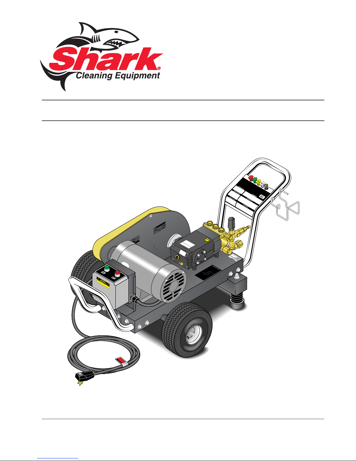
MODEL: BT
OPERATING INSTRUCTION
AND PARTS MANUAL
■ BT-3530 ■ BT-4020 ■ BT-5030
For technical assistance or the SHARK dealer nearest you
visit our website at www.shark-pw.com
#97-727
Page 2

Page 3

Introduction ............................................................................................. 4
Important Safety Information ................................................................ 4-5
Component Identification ......................................................................... 6
Assembly Instructions............................................................................. 7
Operating Instructions ............................................................................. 8
Detergents and General Operating Techniques ........................................ 9
Shut Down and Clean-Up ...................................................................... 10
Storage ................................................................................................. 10
Troubleshooting ................................................................................ 11-12
Preventative Maintenance ..................................................................... 13
Oil Change Record ................................................................................ 13
Exploded View .................................................................................. 14-15
Exploded View Parts List ................................................................. 16-18
Hose & Spray Gun ................................................................................ 19
Downstream Injector ............................................................................. 19
Specifications .................................................................................. 20-21
D Pump Exploded View and Parts List ............................................ 22-23
T Pump Exploded View and Parts List ............................................ 24-25
M Pump Exploded View and Parts List ........................................... 26-27
AR-AL Unloader Exploded View and Parts List .................................... 28
VBA35 Unloader Exploded View and Parts List ................................... 29
VB55 Unloader Exploded View and Parts List ...................................... 30
Warranty
CONTENTS
Model Number ______________________________
Serial Number ______________________________
Date of Purchase ___________________________
The model and serial numbers will be found on a decal attached to
the pressure washer. You should record both serial number and
date of purchase and keep in a safe place for future reference.
3
97-727, 96-721 • REV. 4/06
Page 4
INTRODUCTION & IMPORTANT SAFETY INFORMATION
Thank you for purchasing this Pressure Washer.
All information in this manual is based on the latest
product information available at the time of printing.
We reserve the right to make changes at any time
without incurring any obligation.
Owner/User Responsibility:
The owner and/or user must have an understanding of
PRESSURE WASHER
the manufacturer’s operating instructions and warnings
before using this pressure washer. Warning information
should be emphasized and understood. If the operator is
not fluent in English, the manufacturer’s instructions and
warnings shall be read to and discussed with the operator in the operator’s native language by the purchaser/
owner, making sure that the operator comprehends its
contents.
Owner and/or user must study and maintain for future
OPERATOR’S MANUAL
reference the manufacturers’ instructions.
This manual should be considered a permanent
part of the machine and should remain with it if
machine is resold.
When ordering parts, please specify model and
serial number.
IMPORTANT SAFETY
INSTRUCTIONS
WARNING: When using this machine, basic precautions should always be followed, including the
following:
CAUTION
READ OPERATOR’S
MANUAL
THOROUGHLY
PRIOR TO USE.
2. Know how to stop the machine and bleed pressures quickly. Be thoroughly familiar with the controls.
3. Stay alert — watch what you are doing.
4. All installations must comply with local codes. Contact your electrician, plumber, utility company or
the selling distributor for specific details.
To comply with the National Electrical Code (NFPA
70) and provide additional protection from risk of
electric shock, these pressure washers are
equipped with a UL approved ground fault circuit
4
CAUTION: To reduce the risk of
injury, read operating instructions carefully before using.
1. Read the owner's manual thoroughly. Failure to follow instructions could cause malfunction of the machine and
result in death, serious bodily
injury and/or property damage.
interrupter (GFCI) power cord (120V and 230V
1 ph). All other models must be connected to a
GFCI circuit breaker.
WARNING
RISK OF EXPLOSION:
DO NOT USE WITH
FLAMMABLE LIQUIDS.
WARNING
KEEP WATER SPRAY
AWAY FROM
ELECTRICAL WIRING.
proper voltage and amperage ratings. Do not spray
water on or near electrical components. Do not
touch machine with wet hands or while standing in
water. Always disconnect power before servicing.
7. Grip cleaning wand securely with both hands before starting the cleaner. Failure to do this could
result in injury from a whipping wand.
WARNING
RISK OF INJECTION
OR SEVERE INJURY
TO PERSONS. KEEP
CLEAR OF NOZZLE.
charge stream at people, or severe injury or death
will result.
9. Never make adjustments on machine while in
operation.
97-727, 96-721 • REV. 4/06
WARNING: Flammable liquids
can create fumes which can ignite causing property damage
or severe injury.
WARNING: Risk of explosion —
do not spray flammable liquids.
5. Risk of explosion — do not
spray flammable liquids or
operate in an explosive location.
WARNING: Keep water spray
away from electric wiring or fatal electric shock may result.
6. To protect the operator from
electrical shock, the machine
must be electrically
grounded. It is the responsibility of the owner to connect
this machine to a UL
grounded receptacle of
WARNING: The high pressure
stream of fluid that this equipment can produce can pierce
skin and its underlying tissues,
leading to serious injury and
possible amputation.
8. High pressure developed by
these machines will cause
personal injury or equipment
damage. Use caution when
operating. Do not direct dis-
Page 5
IMPORTANT SAFETY INFORMATION
PRESSURE WASHER
WARNING
WARNING: High pressure spray
can cause paint chips or other
particles to become airborne
and fly at high speeds.
10. Eye safety devices and foot
protection must be worn when
USE PROTECTIVE
EYEWEAR WHEN
OPERATING.
the trigger in the off position for extensive periods
of time as this may cause damage to the pump.
12. Protect from freezing.
13. Be certain all quick coupler fittings are secured
before using pressure washer.
using this equipment.
11. Machines with spray gun
should not be operated with
14. Do not allow acids, caustic or abrasive fluids to
pass through the pump.
15. Inlet water must be cold and clean fresh water.
16. To reduce the risk of injury, close supervision is
necessary when a machine is used near children.
Do not allow children to operate the pressure
washer. This machine must be attended dur-
ing operation.
17. The best insurance against an accident is precaution and knowledge of the machine.
18. Manufacturer will not be liable for any changes
made to our standard machines or any components not purchased from us.
OPERATOR’S MANUAL
5
97-727, 96-721 • REV. 4/06
Page 6
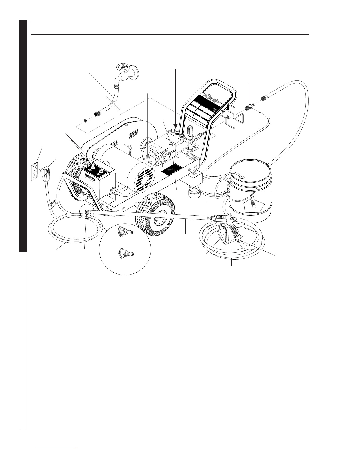
COMPONENT IDENTIFICATION
PRESSURE WASHER
Start/Stop
Switches
Power
Supply
OPERATOR’S MANUAL
Water Supply Hose
(not included)
GFCI
Sight Glass
Pressure Nozzle
Oil Level
Pump Protector
Oil
Dipstick
Pump
Detergent
Injector
Inlet
Connector
Detergent Bucket
(not included)
Detergent
Tube
Spray
Gun
Wand
Power
Cord
Nozzle
Quick
Coupler
Soap
Nozzle
Detergent Injector - Allows you to siphon and mix de-
tergents.
High Pressure Hose - Connect one end to water pump
discharge nipple and the other end to spray gun.
Nozzle Quick Coupler - To easily connect the high
pressure hose and soap nozzle to wand.
Oil Level Sight Glass - A quick visual reference to the
oil level in the pump.
Pump - Develops high pressure.
Pump Protector - Cycles fresh cool water through
pump when recirculating water reaches 140°F.
Trigger
High Pressure Hose
Swivel
Connector
Spray Gun - Must be connected to the high pressure
hose and wand.
Swivel Connector - Connects to the spray gun and
wand. Minimizes hassle of hose coiling.
Wand - Must be connected to the spray gun.
Note: If trigger on spray gun is released for more
than 2 minutes, water will leak from valve. Warm
water will discharge from pump protector onto
floor. This system prevents internal pump damage.
6
97-727, 96-721 • REV. 4/06
Page 7
ASSEMBLY INSTRUCTIONS
PRESSURE WASHER
Spray
Gun
Safety
Latch
High Pressure
Hose
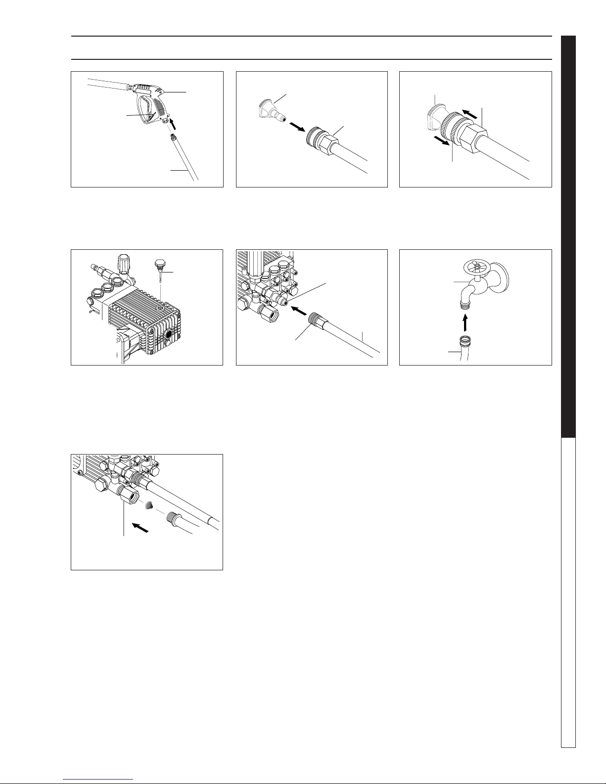
STEP 1: Attach the high pressure
hose to the spray gun using teflon
tape on hose threads.
DipStick
Pressure
Nozzle
Wand
Coupler
STEP 2: Pull the spring-loaded col-
lar of the wand coupler back to insert your choice of pressure nozzle.
Pump
Discharge
Fitting
High
Pressure
Hose
Coupler Collar
Pressure
Nozzle
Coupler
Collar
Wand
Coupler
STEP 3: Release the coupler col-
lar and push the nozzle until the
collar clicks. Pull the nozzle to
make sure it is seated properly.
Cold
Water
Source
Garden
Hose
OPERATOR’S MANUAL
STEP 4: Remove shipping cap and
install oil dipstick. Check pump oil
level by using dipstick or observe oil
level in oil window (if equipped). Use
30 wt. non detergent oil.
Pump
Water Inlet
Garden
Hose
STEP 7: Check inlet filters, remove
debris, then connect the garden
hose to pump water inlet.
CAUTION: Do not run the pump
without water or pump damage
will result.
STEP 5: Connect the high pressure
hose to the pump discharge fitting.
Push coupler collar forward until
secure.
STEP 6: Connect garden hose to
the cold water source.
7
97-727, 96-721 • REV. 4/06
Page 8
PRESSURE WASHER
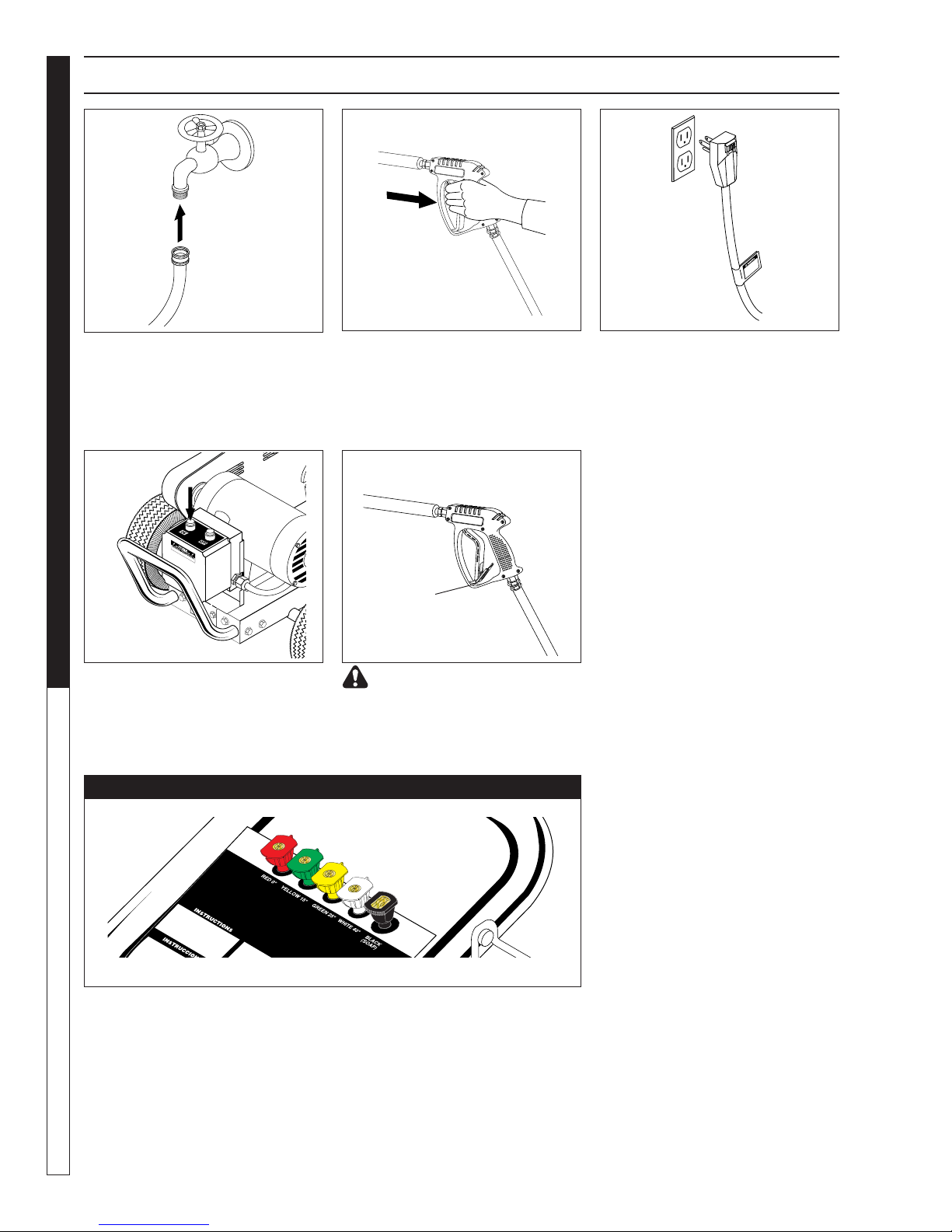
OPERATING INSTRUCTIONS
Cold
Water
Source
Garden
Hose
STEP 1: Connect garden hose to the
cold water source and turn water on
completely. Never use hot water.
OPERATOR’S MANUAL
STEP 4: Turn machine on.
STEP 2: Trigger the spray gun to
eliminate trapped air then wait for a
steady flow of water to emerge from
the spray nozzle.
WARNING! Never replace
nozzles without engaging the
safety latch on the spray gun trigger.
NOZZLES
STEP 3: Connect machine to ad-
equate power source. Push reset
button on GFCI.
Safety
Latch
The five color-coded quick connect nozzles provide a wide array of spray
widths from 0° to 45° and are easily accessible when placed in the convenient rubber nozzle holder, which is provided on the front of the machine.
NOTE: For a more gentle rinse, select the white 40° or green 25° nozzle.
To scour the surface, select the yellow 15° or red 0° nozzle. To apply detergent select the black nozzle.
8
97-727, 96-721 • REV. 4/06
Page 9
DETERGENTS AND GENERAL CLEANING TECHNIQUES
PRESSURE WASHER
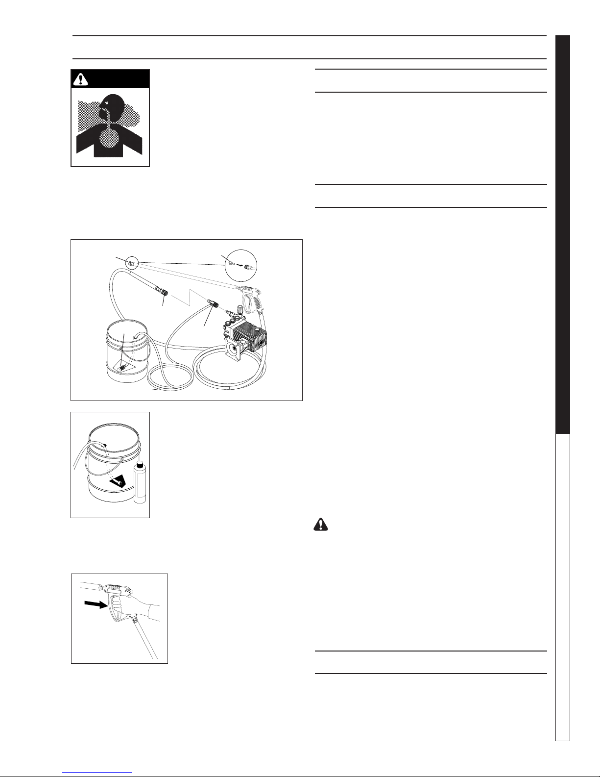
WARNING
WARNING: Some detergents may
be harmful if inhaled or ingested,
causing severe nausea, fainting
or poisoning. The harmful elements may cause property damage or severe injury.
STEP 1: Connect detergent injector to discharge nipple
on machine, Connect high pressure hose to injector
with quick coupler. (Check to make sure locking coupler sleeves are in proper position before applying water pressure.)
Quick
Coupler
Filter
Discharge
Nipple
Soap
Nozzle
Detergent
Injector
THERMAL PUMP PROTECTION
If you run the engine on your pressure washer for 3-5
minutes without pressing the trigger on the spray gun,
circulating water in the pump can reach high temperatures. When the water reaches this temperature, the
pump protector engages and cools the pump by discharging the warm water onto the ground. This thermal
device prevents internal damage to the pump.
CLEANING TIPS
Pre-rinse cleaning surface with fresh water. Place detergent suction tube directly into cleaning solution and apply to surface at low pressure (for best results, limit
your work area to sections approximately 6 feet square
and always apply detergent from bottom to top). Allow
detergent to remain on surface 1-3 minutes. Do not allow detergent to dry on surface. If surface appears to
be drying, simply wet down surface with fresh water. If
needed, use brush to remove stubborn dirt. Rinse at
high pressure from top to bottom in an even sweeping
motion keeping the spray nozzle approximately 1 foot
from cleaning surface. Use overlapping strokes as you
clean and rinse any surface. For best surface cleaning
action spray at a slight angle.
OPERATOR’S MANUAL
High Pressure Hose
STEP 2: Use detergent designed
specifically for pressure washers.
Household detergents could damage the pump. Prepare detergent solution as required by the manufacturer. Fill a container with pressure
washer detergent. Place the filter
end of detergent suction tube into
the detergent container.
STEP 3: With safety latch on spray gun engaged, secure black detergent nozzle into quick coupler.
NOTE: Detergent cannot be applied using red, yellow,
green or white nozzles.
STEP 4: With the engine running, pull trigger to operate machine. Liquid detergent is drawn
into the machine and mixed with
water. Apply detergent to work
area. Do not allow detergent to
dry on surface.
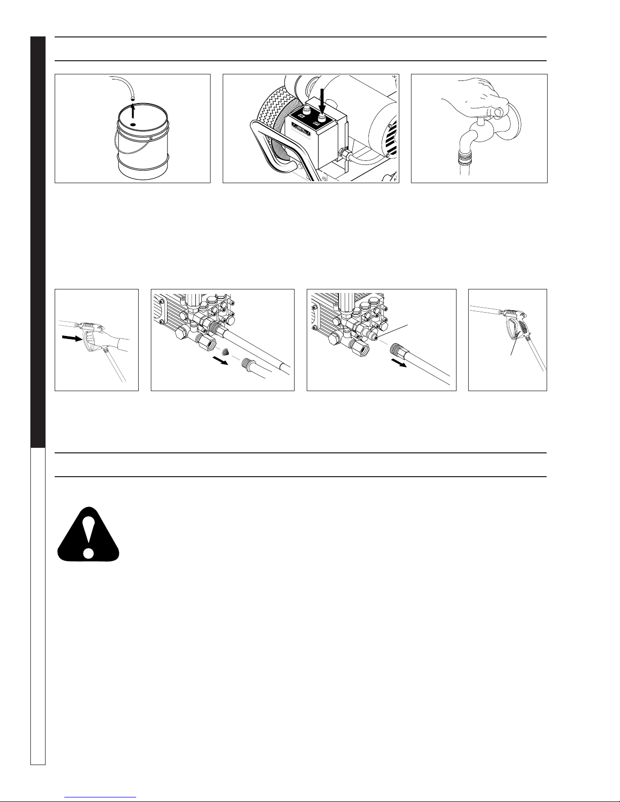
IMPORTANT: You must flush the detergent injection
system after each use by placing the suction tube
into a bucket of clean water, then run the pressure
washer in low pressure for 1-2 minutes.
97-727, 96-721 • REV. 4/06
Recommendations:
• Before cleaning any surface, an inconspicuous area
should be cleaned to test spray pattern and distance for maximum cleaning results.
• If painted surfaces are peeling or chipping, use extreme caution as pressure washer may remove the
loose paint from the surface.
• Keep the spray nozzle a safe distance from the surface you plan to clean. High pressure wash a small
area, then check the surface for damage. If no damage is found, continue to pressure washing.
CAUTION - Never use:
• Bleach, chlorine products and other corrosive
chemicals
• Liquids containing solvents (i.e., paint thinner, gasoline, oils)
• Tri-sodium phosphate products
• Ammonia products
• Acid-based products
These chemicals will harm the machine and will damage the surface being cleaned.
RINSING
It will take a few seconds for the detergent to clear. Apply
safety latch to spray gun. Remove black soap nozzle
from quick coupler. Select and install desired high pressure nozzle. NOTE: You can also stop detergent from
flowing by removing detergent siphon tube from bottle.
9
Page 10
PRESSURE WASHER
SHUTTING DOWN AND CLEAN-UP
STEP 1: Remove detergent suction
tube from container and insert into
one gallon of fresh water. Slide
nozzle forward for low pressure or
to connect black detergent nozzle.
Pull trigger on spray gun and siphon
water for one minute.
OPERATOR’S MANUAL
Pump
Water
Inlet
STEP 4: Press trig-
ger to release water pressure.
STEP 5: Disconnect the garden
hose from the water inlet on the
machine.
STEP 2: Turn off machine. STEP 3: Turn off water
supply.
High
Pressure
Outlet
Safety
Latch
STEP 6: Disconnect the high
pressure hose from high pressure outlet.
STEP 7: Engage
the spray gun
safety lock.
STORAGE
Pump Storage
CAUTION: Always store your pressure washer in a location where the
temperature will not fall below 32° F
(0° C). The pump in this machine is
CAUTION
FREEZE DAMAGE IS NOT COVERED BY WARRANTY.
If you must store your pressure washer in a location
where the temperature is below 32° F, you can minimize the chance of damage to your machine by draining your machine as follows:
1. Stop the pressure washer and detach supply hose
and high pressure hose. Squeeze the trigger of the
spray gun to drain all water from the wand and
hose.
2. Restart pressure washer and let it run briefly (about
5 seconds) until water no longer discharges from
the high pressure outlet.
10
susceptible to permanent damage if
frozen.
97-727, 96-721 • REV. 4/06
Page 11

TROUBLESHOOTING
MELBORPESUACELBISSOPNOITULOS
GNINNURPMUP
TUBYLLAMRON
NOWOLERUSSERP
NOITALLATSNI
lnU.yrassecenfiecalperdnakcehC
riagnikcuspmuP .egapeesriafoy
gnikcitssevlavkcehC.yrassecenfiecalperronaelcdnakcehC
ytluaftaesevlavredao
dezisyltcerrocnielzzoN.yrassecenfiecalperdnakcehC
PRESSURE WASHER TROUBLESHOOTING GUIDE
tilibissopdnaylppusretawkcehC
gnikcapnotsipnroW.yrassec
GNITAUTCULF
ERUSSERP
WOLERUSSERP
FODOIREPRETFA
ESULAMRON
YSIONPMUP
RETAWFOECNESERP
LIOPMUPNI
nrowsevlaV.yrassecenfiecalperdnakcehC
evlavniegakcolB.yrassecenfit
riagnikcuspmuP.snoitcennocylppusretawkcehC
gnikcapnotsipnroW.yrassecenfiecalperdnakcehC
re
tawtneiciffusnI.egakaerbrofesohdnaretlifkcehC
nrowelzzoN.yrassecenfieca
nrowsevlavyreviledronoitcuS.yrassecenfiecalperdnakcehC
sevlavyreviledronoitcuS
dekcolb
nrowtaesevlavredaolnU.yrassecenfiecalperdnakcehC
egakcapnotsipnroW.yrassecenfiecalper
enilnoitcusniriA .enilnoitcusnosnoitcennocdnaylppusretawkcehC
ronoitcuskaewronekorB
gni
rpsevlavyreviled
sevlavnirettamngieroF.yrassecenfinaelcdnakcehC
sgniraebnroW.y
retawfoerutarepmetevissecxE041wolebotecudeR
nrowlaesliO.yrassecenfiecalperdnakcehC
rianiytidimuhhgiH.netfosaeciwtlioegnahc
lperdnakcehC
dnakcehC
dnakcehC
enfiecalperdnakcehC
uonaelcdnakcehC
.yrass
ecenfinaelcdnakcehC
.yrassecenfiecalperdnakcehC
rassecenfiecalperdnakcehC
o
.F
GNIPPIRDRETAW
PMUPREDNUMORF
GNIPPIRDRETAW
PMUPMORF
ROTCETORP
GNIPPIRDLIO
ERUSSERP-HGIHNI
ESOH
S
NOITARBIVEVISSECXE
nrowgnikcapnotsiP.yrassecenfiecalperdnakcehC
nrowgnikcapnotsiP.yrassec
nrowreniaterregnulpgniR-O.yrassecenfiecalperdnakcehC
h
gihooterusserpylppusretaW
)isp09revo(
noitisopffoehtnisinugyarp
setunim5revorof
nrowlaesliO.yrassecenfiecalperdnakc
ehtfogninoitcnufralugerrI
sevlavpmup
97-727, 96-721 • REV. 4/06
C
enfiecalperdnakcehC
.rotalugeragnisuerusserpylppusretawrewoL
.setunim5revorofesunitonfiffoenihcamnruT
ehC
.yrassecenfiecalperdnakceh
11
Page 12

TROUBLESHOOTING
PROBLEM POSSIBLE CAUSE SOLUTION
MOTOR WILL NOT
START
MOTOR
OVERHEATING
PRESSURE WASHER TROUBLESHOOTING GUIDE
Usually caused by line trouble, such
as single phasing at the starter
Overload. Compare actual amps
(measured) with nameplate rating
Single phasing Check current at all phases (should be
Improper ventilation Check external cooling fan to be sure air is
Unbalanced voltage Check voltage at all phases (should be
Over voltage or under voltage Check input voltage at each phase to motor.
Open stator winding Check stator resistance at all three phases
Improper connections Inspect all electrical connections for proper
Check source of power. Check overloads,
fuses, controls, etc.
Locate and remove source of excessive
friction in motor or load.
Reduce load or replace with motor of greater
capacity.
approximately equal) to isolate and correct
problem.
moving properly across cooling fins.
Excessive dirt build-up on motor. Clean
motor.
approximately equal) to isolate and correct
the problem.
for balance.
termination, clearance, mechanical strength
and electrical continuity. Refer to wiring
diagrams.
BEARING
OVERHEATING
GROWLING OR
WHINING
Misalignment Check and align motor and driven
Excessive belt tension Reduce belt tension to proper point for load.
Excessive grease in bearing Remove grease until cavity is approximately
Insufficient grease in bearing Add grease until cavity is approximately 3/4
Dirt in bearing Clean bearing cavity and bearing. Repack
Bad bearing Replace bearing. Clean all grease from
equipment.
3/4 filled.
filled.
with correct grease until cavity is
approximately 3/4 filled.
cavity and new bearing. Repack with correct
grease until cavity is approximately 3/4 filled.
12
97-727, 96-721 • REV. 4/06
Page 13

PREVENTATIVE MAINTENANCE
This pressure washer was produced with the best available materials and quality craftsmanship. However, you
as the owner have certain responsibilities for the correct care of the equipment. Attention to regular preventative
maintenance procedures will assist in preserving the performance of your equipment. Contact your dealer for
maintenance. Regular preventative maintenance will add many hours to the life of your pressure washer. Perform maintenance more often under severe conditions.
PRESSURE WASHER
Pump Oil
Inspect Daily inspect the oil level
Change After first 50 hours, then every 500 hours or annually
Replace High Pressure Nozzle Every 6 months
Replace Quick Connects Anually
Clean Water Screen/Filter Weekly
Replace HP Hose Anually if there is any sign of wear
Grease Motor Every 10,000 hours or annually
General Inspection Inspect the motor at regular intervals, approximately every 500 hours of operation,
or every 3 months, whichever occurs first. Keep the motor clean and the ventilation
openings clear. The following steps should be performed at each inspection:
WARNING: Do not touch electrical connections before you first ensure that power
has been disconnected. Electrical shock can cause serious or fatal injury. Only
qualified personnel should attempt the installation, operation and maintenance of
this equipment.
1. Check that the motor is clean. Check that the interior and exterior of the motor
is free of dirt, oil, grease, water, etc. Oily vapor, paper pulp, textile lint, etc.
can accumulate and block motor ventilation. If the motor is not properly ventilated overheating can occur and cause early motor failure.
2. Check all electrical connectors to be sure that they are tight.
Lubrication & Bearings Bearing grease will lose its lubricating ability over time, not suddenly. The lubricating
ability of a grease (over time) depends primarily on the type of grease, the size of the
bearing, the speed at which the bearing operates and the severity of the operating
conditions. Good results can be obtained if the following recommendations are used
in your maintenance program.
Type of Grease A high grade ball or roller bearing grease should be used. Recommended greases for
standard service conditions are: Shell Dolium R (Factory installed) or Chevron SRI.
OPERATOR’S MANUAL
Date Oil Changed
Month/Day/Year
OIL CHANGE RECORD
Estimated Operating
Hours Since Last
Oil Change
97-727, 96-721 • REV. 4/06
Date Oil Changed
Month/Day/Year
Estimated Operating
Hours Since Last
Oil Change
13
Page 14

EXPLODED VIEW
PRESSURE WASHER
53
47
OPERATOR’S MANUAL
68
66
64
65
63
1
2
7
48
36
51
100
38
57
46
58
50 49
46
59
24
27
106
39
37
67
4
5
7
6
29
21
38,39
6
5
45
44
77
38
29
70
69
5
28
5
75
3
2
5
76
5
76
62
74
60
61
25
23
102
49
5
9
91
43
35
46
48
8
3927
73
71
47
42,95,96,104
44
5
108
107
46
48
91
43
9
65
23
Model
PE3-11024
52
49
45
49
5
50
54
39,77,106
36
37
BT-35007A,
25
18
6
2
28
38
PE4-3000A
102
103
101
27
97
65
63
39
39
77
106
69
39, 106
38
99
5
75
5
48
90
89
3
67
28
98
64
63
68
92
77
3
2
1
66
14
97-727, 96-721 • REV. 4/06
Page 15

EXPLODED VIEW
PRESSURE WASHER
BT Models 353007,
402007, 503007
41
41
99
40
40
83
26
26
82
84
88
6
85
87
86
22
5
72
22
33
34
79
80
34
78
105
PE4-20024,
4-30024,
5-30024
41
PE3-11024D
81
5
6
26
22
33
34
40
32
31
19
6
5
94
30
20
93
OPERATOR’S MANUAL
11
17
14
15
16
12a
12b
97-727, 96-721 • REV. 4/06
13
6
5
5
6
10
15
Page 16

EXPLODED VIEW PARTS LIST
ITEM PART NO. DESCRIPTION QTY
1 90-2004 Nut, Jam, ESNA, NC, 5/8" 2
2 90-4005 Washer, Flat, SAE, 5/8" 4
3 4-0307 Tire & Wheel Cmpl, Steel 6"
(All Models except 3-11024) 2
4-0303 Wheel & Tire Assembly,
4" Tube, (3-11024) 2
4 95-07101130 Handle, Bumper, 1-1/4",
PRESSURE WASHER
5 90-4002 Washer, Flat, SAE, 3/8" (BT,
6 90-2002 Nut, ESNA, NC, 3/8" (BT,
7 90-10220 Bolt, 3/8" x 3-1/2", Tap 2
8 95-07101135 Bracket, Belt Tension 1
OPERATOR’S MANUAL
9 90-2020 Nut, Cage, 3/8", 12 Gauge 2
10 95-07101219 Bracket, Foot, Black (PE) 1
95-07101219R Bracket, Foot, Red (BT) 1
11 92-102 Foot Assembly
12a 90-1023 Bolt, 3/8" x 5", NC 2
12b 90-40125 Washer, 3/8" x 1", Steel 2
13 2-01041 Pad, Soft Rubber 2
14 90-4015 Washer, 2-1/2" x 7/16",
15 95-07161114A Tube, Foot, Bolt PC 2
16 90-5009 Spring, Foot, Compression 2
17 2-0107 Bellows, Leg (Boot) 2
18 95-07101216 Frame, Black, Welded
95-07101222 Frame, Large, Black,
95-07101222R Frame, Large, Red (BT) 1
19 11-0364 Label, BT 1
10-99060 Label, PE 1
20 95-07101145 Handle, 1-1/4", Chrome 1
21 6-05172 Locknut, 3/4" 2
22 2-2007 Nipple, 3/4" x 3/8" Male 1
23 95-07101021 Bracket, Electrical Box (All
95-07101022 Bracket, Electrical Box
24 10-08018 Label, Warning Service
25 2-0106 Cushion, Pump 2
26 Unloader, See Specifications Pages
Chrome Plated 1
PE3-11024) 28
(All Other PE Models) 30
PE3-11024) 16
(All Other PE Models) 14
(Items 11-17) 2
Flat Washer 2
(PE3-11024D) 1
Welded (All Other PE Models)1
Models except 353007A,
4-30024A) 1
(353007A, 4-30024A) 1
Cord 1
ITEM PART NO. DESCRIPTION QTY
27 6-01060 Cord, w/GFCI, 120V/20 Amp,
36' (3-11024D) 1
6-0105 Cord, Service 12/4 (353007C;
4-20024B,C; 402007B,C;
4-30024C; 503007C;
5-30024C) 15 ft.
6-01059 Cord w/GFCI, 240V/30Amp
36' (402007A, 4-20024A) 1
6-0109 Cord, Service,10/4
(353007B; 4-30024B) 15 ft.
6-010690 GFCI, 240V, 40A, 1 PH, 37'
Cord (353007A; 4-30024A) 1
6-01021 Cord, Service, 8/4
(503007B; 5-30024B) 15 ft.
28 6-0108 Cord, Service, SEO, 10/3
(402007A; 4-20024A) 2.75 ft.
6-0104 Cord Service SEO, 12/3
(3-11024D) 2 ft.
6-0105 Cord, Service, SEO, 12/4
(353007C; 402007B,C;
4-20024B,C; 4-30024C;
5-30024C; 503007C) 2.75 ft.
6-0109 Cord, Service, SEO, 10/4
(353007B; 4-30024B) 2.75 ft.
6-0102 Cord, Service SEO 8/3
(353007A; 4-30024A) 4.66 ft.
6-01021 Cord, Service SEO, 8/4
(5-30024B; 503007B) 2.75 ft.
29 6-051595 Fitting, STRT, LQ Tite, Plastic
(353007B,C; 402007A,B,C;
4-20024A,B,C;4-30024B,C;
5-30024C; 503007C) 2
6-05170 Strain Relief, Water Tight
(5-30024B, 503007B) 2
30 2-0103 Grommet, Rubber, 1/8" 5
31 4-12804000 Nozzle, SAQC MEG 0004
Red (4-30024; 353007) 1
4-12804015 Nozzle, SAQC MEG 1504
Yellow (4-30024; 353007) 1
4-12804025 Nozzle, SAQC MEG 2504
Green (4-30024; 353007) 1
4-12804040 Nozzle, SAQC MEG 4004
White (4-30024; 353007) 1
4-12805500 Nozzle SAQC MEG 0005.5
Red (3-11024, 503007,
5-30024) 1
4-12805515 Nozzle, SAQC MEG 15055
Yellow (3-11024, 503007,
5-30024) 1
4-12805525 Nozzle, SAQC MEG 25055
Green (3-11024, 503007,
5-30024) 1
4-12805540 Nozzle, SAQC MEG 4055 White
(3-11024, 503007, 5-30024) 1
16
97-727, 96-721 • REV. 4/06
Page 17

EXPLODED VIEW PARTS LIST
PRESSURE WASHER
ITEM PART NO. DESCRIPTION QTY
31 4-12806000 Nozzle, SAQC MEG 0506
Red (4-20024, 402007) 1
4-12806015 Nozzle, SAQC MEG 1506
Yellow (4-20024, 402007) 1
4-12806025 Nozzle, SAQC, Meg 2506
Green (4-20024, 402007) 1
4-12806040 Nozzle, SAQC MEG 4006
White (4-20024, 402007) 1
32 4-16540 Nozzle, Brass, Soap 1
33 2-1902 Strainer, Inlet Garden Hose 1
34 2-10942 Swivel, 1/2" MP x 3/4" GHF 1
35 6-05154 Strain Relief, Plastic, LQ Tite
(3-11024) 1
6-05181 ▲ Locknut, 1/2” (3-11024) 1
36 Overload, See Specifications Pages
37 Contactor, See Specifications Pages
38 90-1991 Screw, 10/32" x 1/2" (3-11024D,
4-02007A, 402007A) 4
(353007A, 4-30024A) 7
(353007B,C; 402007B,C;
503007B,C; 4-20024B,C;
4-30024B,C; 5-30024B,C) 5
39 90-017 Nut, 10/32" Keps (4-20024A,
402007A; 353007B,C;
402007B,C; 503007B,C;
4-20024B,C; 4-30024B,C;
5-30024B,C) 6
(3-11024D) 7
(353007, 4-30024A) 10
40 2-30082 Pump Protector, 1/2", PTP
(All Models Except 3-11024) 1
2-300812 Pump Protector 1/4” 145°
(3-11024) 1
41 Pump, See Specifications Pages
42 Motor, See Specifications Pages
43 90-1007 Bolt, 5/16" x 1", NC HH
(3-11021) 4
90-1017 Bolt, 3/8" x 1-1/4", NC HH
(All Models Except 3-11021) 4
44 90-4001 Washer, 5/16" Flat (3-11021) 4
90-4002 Washer, 3/8" Flat (All Models
Except 3-11021) 4
45 90-2001 Nut, 5/16" ESNA (3-11021) 4
90-2002 Nut, 3/8" ESNA (All Models
Except 3-11021) 4
46 90-4001 Washer, 5/16" Flat 6
47 90-2001 Nut, 5/16" ESNA, NC 3
48 90-1020 Bolt, 3/8" x 2", NC HH 8
49 90-4000 Washer, 1/4" Flat, SAE 4
50 90-2000 Nut, 1/4" ESNA, NC 2
51 90-1006 Bolt, 5/16" x 3/4", NC HH 1
97-727, 96-721 • REV. 4/06
ITEM PART NO. DESCRIPTION QTY
52 95-07101211 Back Plate, Belt Guard,
Large (All Models Except
3-11024) 1
95-07101213 Back Plate, Belt Guard,
Small (3-11024) 1
53 2-01171 Belt Guard, Small
(PE3-11024) 1
2-01172 Belt Guard, Large (PE) 1
2-0117201 Belt Guard, Large (BT) 1
54 90-1007 Bolt, 5/16" x 1" NC, HH 2
55 10-020PE ▲ Label, PE 1
56 10-2031100 ▲ Label, 3-1100 1
10-2042000 ▲ Label, 4-2000 1
10-2043000 ▲ Label, 4-3000 1
10-2053000 ▲ Label, 5-3000 1
57 Pump, See Bushing Specifications Pages
58 Motor, See Bushing Specifications Pages
59 Motor, See Pulley Specifications Pages
60 Pump, See Pulley Specifications Pages
61 Belt, See Specifications Pages
62 6-03911 Lid, Plastic, Carlon (3-11024) 1
63 6-03904 Enclosure, Fiberglass, Nema4X
(except 3-11024, 35007A,
4-30024A) 1
6-03909 Box, Plastic 10" x 8" x 6"
(353007, 4-30024A) 1
64 10-08015A Label, OFF/ON for Push Button
(All Models Except 3-11024) 1
65 10-08021 Label, Disconnect
Power Supply 1
66 6-2021 Switch, Green Push Button,
CH E22PB3 (All Models
Except 3-11024) 1
67 6-2001 Block, Contact, N/O, CH E22B2
(All Models Except 3-11024) 1
68 6-2022 Switch, Red Push Button, CH
E22EB2(All Models Except
3-11024) 1
69 6-2000 Block, Contact, N/C, CH E22B1
(All Models Except 3-11024) 1
70 6-021595 Din Rail (All Models Except
(3-11024D, 353007A, 4-20024A,
4-30024A, 402007A) 4"
71 6-03910 Box, Electric (3-11024 only) 1
72 2-1044 Plug, Brass 1/8"
(353007, 402007, 503007) 1
73 6-051595 Strain Relief, STRT, LQ Tite
Large, 3/4" (3-11024) 1
6-05172 ▲ Locknut, 3/4” (3-11024) 1
74 6-020204 Switch, 2 Pos., 1-3 PH
(3-11024) 1
75 90-1016 Bolt, 3/8" x 1", NC 4
OPERATOR’S MANUAL
17
Page 18

EXPLODED VIEW PARTS LIST
ITEM PART NO. DESCRIPTION QTY
76 90-2007 Nut, 3/8" Hex NC 2
77 11-1042 Label, Ground 1
78 2-1042 Tee, 1/2" (4-20024,
4-30024, 5-30024) 1
79 4-02110000 Hose, 1/2" Push-On (4-20024,
4-30024, 5-30024) 1.3 ft.
80 2-1105 Swivel, 1/2" JIC Fem, Push-On
PRESSURE WASHER
81 2-1062 Elbow, 1/2" JIC x 1/2", 90°
82 4-02047720 Hose, 3/8" x 20", 2 Wire,
83 2-0053 Elbow, 1/2" JIC x 3/8", 90°
84 2-0051 Nipple, 1/2" JIC x 3/8", Pipe
OPERATOR’S MANUAL
85 2-0006 Nipple, 3/8", Hex (4-20024,
86 95-07101216/B Block, Unloader, 3/8" x 3/8",
87 2-1060 Elbow, 1/2" x 3/8", 90° (4-20024,
88 90-1020 Bolt, 3/8" x 2", NC HH (4-20024,
89 90-10343 Bolt, 10mm x 20mm, HH (All
90-1030 Bolt, 8mm x 16mm HH
90 90-400910 Washer, 7/16" Lock, Split(All
90-4009 Washer, 3/8", Lock, Split Ring
91 90-4007 Washer, 3/8" x 1-1/2", Fender
90-4006 Washer, 5/16” x 1-1/4” Fender
92 6-05172 ▲ Locknut, 3/4” Conduit
93 95-07102382 Hanger, Hose & Wand 1
94 90-20012 Nut, 5/16" Whiz Loc, Flange 2
(4-20024, 4-30024, 5-30024) 2
(4-20024, 4-30024, 5-30024) 1
Pressure Loop (4-20024,
4-30024, 5-30024) 1
(4-20024, 4-30024, 5-30024) 1
(4-20024, 4-30024, 5-30024) 1
4-30024, 5-30024) 1
Brass (4-20024, 4-30024,
5-30024) 1
4-30024, 5-30024) 1
4-30024, 5-30024) 2
Models except 3-11024) 4
(3-11024) 4
Models except 3-11024) 4
(3-11024) 4
(All Models Except 3-11024) 6
(3-11024) 6
(353007A, 4-30024A) 2
ITEM PART NO. DESCRIPTION QTY
95 6-051595 ▲ Strain Relief, Watertite
(3-11024D; 353007B,C;
4-20024A,B,C; 4-30024B,C;
402007A,B,C) 1
6-051700 ▲ Strain Relief, 1" Metal
(4-30024A, 5-30024C,
503007C, 353007A) 1
6-051701 Strain Relief, 1” (5-30024B,
503007B) 1
96 6-05181B ▲ Lock Nut, 3/4" (3-11024D;
353007B,C; 4-20024A,B,C;
4-30024B,C; 402007A,B,C) 1
6-05182 Locknut, 1”(353007A;4-30024A;
503007B,C; 5-30024B,C) 1
97 6-05170 Strain Relief, 3/4 Watertight
(353007A, 4-30024A) 1
98 6-051595 Strain Relief, 3/4 Watertight
Plastic (353007A, 4-30024A) 1
99 9.800-049.0 Label, Manufacturer’s Cleaning
Solution 1
100 10-99055 Label (PE) 1
11-0332 Label (BT) 1
101 95-07290068 Stand-Off Electrical Box
(353007A, 4-30024A) 1
102 90-1028 Eye Bolt, 1/4” x 1” 2
103 90-5004 Spring, Pull, Belt Guard 1
104 11-1042 ▲ Label, Ground (Motor) 1
105 4-011184 Chemical Injector Assy. 1
106 90-1994 Screw, 10/32” x 1-1/4” Ground
(All Models Except 3-11024D)1
90-100030 Screw, 10/32” x 3/4” Ground
(3-11024D) 1
107 10-08016 Label, Indoor Use 1
108 10-9999 Label, Clear Lexan 1
109 90-1999 Screw, 10/32” x 3/4” (402007A,
4-20024A) 3
▲ Not Shown
18
97-727, 96-721 • REV. 4/06
Page 19

HOSE & SPRAY GUN ASSEMBLY
1
PRESSURE WASHER
8
11
3
2
11
4,5
10
12
7
6
9
OPERATOR’S MANUAL
HOSE & SPRAY GUN ASSEMBLY PARTS LIST
ITEM PART NO. DESCRIPTION QTY
1 2-2002 Coupler, 3/8" Female 1
2-0121 ▲ Quick Coupler O-Ring
Large 1
2 4-02043450C Hose 3/8” x 50’ w/Coupler
(PE Models) 1
4-02093450BC Hose 3/8” x 50’ 1 Wire Blue,
w/Coupler (BT Models) 1
3 4-01212 Spray Gun, Shut-off
(PE Models) 1
4-01246 (BT Models) 1
4 4-0110410 Wand, Straight, Assy (PE
Models) 1
4-011053 Wand, SS (PE Models) 1
4-0110322 Wand w/Side Grip, Assy (BT
Models) 1
4-011032 Wand w/Side Grip (BT
Models) 1
5 4-011231 Cover, Wand (PE Models) 1
97-727, 96-721 • REV. 4/06
ITEM PART NO. DESCRIPTION QTY
6 4-16540 Brass Soap Nozzle 1
7 Nozzle, See Page 16, Item #31
8 3-12021 Injector, Chem, Non-Adj,
3-5 GPM 1
9 2-2000 Coupler, 1/4" Female 1
2-0119 ▲ Quick Coupler O-Ring
Small 1
10 4-02080000 Tube, 1/4” x 1/2” Clear Vinyl 6 ft.
11 2-9040 Clamp, Hose 2
12 2-1904 Strainer, 1/4” Hose Barb 1
▲ Not Shown
19
Page 20

SPECIFICATIONS
PARTS SPECIFICATIONS
MOTORPUMP
Pump Unloader Pump Pump Pulley Pump Bushing Motor Motor
Model Pump Part No. Part No. Pulley Part No. Bushing Part No. Size Voltage/ph Hz
3-11024D LD3030 5-1709 5-3329 AK74H 5-40107401 24MM 5-512024 2HP 120V/1PH 60
4-20024A LT5030 5-1728 5-3208 2AK84H 5-40208401 25MM 5-512025 6.2HP 230V/1PH 60
4-20024B LT5030 5-1728 5-3208 2AK84H 5-40208401 25MM 5-512025 6.2HP 230V/3PH 60
4-20024C LT5030 5-1728 5-3208 2AK84H 5-40208401 25MM 5-512025 6.2HP 460V/3PH 60
4-30024A LT5030 5-1728 5-3208 2BK90H 5-40509001 25MM 5-512025 7.5HP 230V/1PH 60
4-30024B LT5030 5-1728 5-3208 2BK90H 5-40509001 25MM 5-512025 7.5HP 230V/3PH 60
4-30024C LT5030 5-1728 5-3208 2BK90H 5-40509001 25MM 5-512025 7.5HP 460V/3PH 60
5-30024B LT5030 5-1728 5-3208 2BK65H 5-40506501 25MM 5-512025 10HP 230V/3PH 60
5-30024C LT5030 5-1728 5-3208 2BK65H 5-40506501 25MM 5-512025 10HP 460V/3PH 60
PRESSURE WASHER SPECIFICATIONS
402007A SM4030 5-1410 5-3029 2AK74H 5-40207401 24MM 5-512024 6.2HP 230V/1PH 60
402007B SM4030 5-1410 5-3029 2AK74H 5-40207401 24MM 5-512024 6.2HP 230V/3PH 60
402007C SM4030 5-1410 5-3029 2AK74H 5-40207401 24MM 5-512024 6.2HP 460V/3PH 60
353007A SM4030 5-1410 5-3029 2BK70H 5-40507001 24MM 5-512024 7.5HP 230V/1PH 60
353007B SM4030 5-1410 5-3029 2BK70H 5-40507001 24MM 5-512024 7.5HP 230V/3PH 60
353007C SM4030 5-1410 5-3029 2BK70H 5-40507001 24MM 5-512024 7.5HP 460V/3PH 60
503007B SM5030 5-1415 5-3029 2BK52H 5-40505201 24MM 5-512024 10HP 230V/3PH 60
503007C SM5030 5-1415 5-3029 2BK52H 5-40505201 24MM 5-512024 10HP 460V/3PH 60
20
97-727, 96-721 • REV. 4/06
Page 21

SPECIFICATIONS
MOTOR (CON'T)
Motor Motor Pulley Motor Bushing Belt Belt Contactor Overload
Model Model Pulley Part No. Bushing Part No. Size Part No. Part No. Part No.
3-11024D 5-1047 AK32X5/8" 5-40103258 N/A N/A AX35 (1) 5-
4-20024A 5-10401 2AK46H 5-40204601 HX1-1/8" 5-511113 AX42 (2) 5-602042 6-4019 N/A
4-20024B 5-1011 2AK46H 5-40204601 HX1-1/8" 5-511113 AX42 (2) 5-602042 6-4011 6-5011
4-20024C 5-1011 2AK46H 5-40204601 HX1-1/8" 5-511113 AX42 (2) 5-602042 6-4009 6-5009
4-30024A 5-1013 2BK40H 5-40504001 HX1-3/8" 5-511138 BX42 (2) 5-604042 6-4019 6-5015
4-30024B 5-10145 2BK40H 5-40504001 HX1-3/8" 5-511138 BX42 (2) 5-604042 6-4011 6-5012
4-30024C 5-10145 2BK40H 5-40504001 HX1-3/8" 5-511138 BX42 (2) 5-604042 4-4009 6-5009
5-30024B 5-1018 2BK36H 5-40503601 HX1-3/8" 5-511138 BX38 (2) 5-604038 6-4014 6-5013
5-30024C 5-1018 2BK36H 5-40503601 HX1-3/8" 5-511138 BX38 (2) 5-604038 6-4009 6-5010
402007A 5-10401 2AK46H 5-40204601 HX1-1/8" 5-511113 AX40 (2) 5-602040 6-4019 N/A
402007B 5-1011 2AK46H 5-40204601 HX1-1/8" 5-511113 AX40 (2) 5-602040 6-4011 6-5011
402007C 5-1011 2AK46H 5-40204601 HX1-1/8" 5-511113 AX40 (2) 5-602040 6-4009 6-5009
353007A 5-1013 2BK36H 5-40503601 HX1-3/8" 5-511138 BX37 (2) 5-604037 6-4019 6-5015
353007B 5-10145 2BK36H 5-40503601 HX1-3/8" 5-511138 BX37 (2) 5-604037 6-4011 6-5012
353007C 5-10145 2BK36H 5-40503601 HX1-3/8" 5-511138 BX37 (2) 5-604037 4-4009 6-5009
503007B 5-1018 2BK45H 5-40504501 HX1-3/8" 5-511138 BX36 (2) 5-604036 6-4014 6-5013
503007C 5-1018 2BK45H 5-40504501 HX1-3/8" 5-511138 BX36 (2) 5-604036 6-4009 6-5010
602035
N/A N/A
PRESSURE WASHER SPECIFICATIONS
21
97-727, 96-721 • REV. 4/06
Page 22

5-1709
PRESSURE WASHER
PUMP EXPLODED VIEW
OPERATOR’S MANUAL
PUMP EXPLODED VIEW PARTS LIST
ITEM PART NO. DESCRIPTION QTY
1 70-020292 Crankcase 1
2* See Kits Below Plunger Oil Seal 3
3* 70-060181 O-Ring Ø1.78 x 28.30 3
4* 70-120131 Pressure Ring 15mm 3
5* See Kits Below "V" Seal, 15mm 6
6* 70-030048 Support Ring 15mm 6
7* 70-030049 Intermed. Ring 15mm 3
8 70-160120 Brass Plug 1/2" 1
9 70-060307 Copper Washer 1/2" 1
10 70-160228 Manifold Housing 1
11* 70-060155 O-Ring Ø1.78 x 15.54 6
12* See Kits Below Valve Assembly 6
13* 70-060122 O-Ring Ø2.62 x 18.77 6
14 70-160147 Valve Plug 6
15 70-060308 Copper Washer 1/4 1
EUQROT
SCEPS
#metIsbl-.tF
4156
7122
528
439
3431
ITEM PART NO. DESCRIPTION QTY
16 70-160121 Brass Plug G1/4 1
17 70-180118 Manifold Stud Bolt 8
18 70-140001 Washer 8
19 70-060306 Copper Washer 3/8 1
20 70-160117 Brass Plug 3/8 2
25 70-180112 Screw 12
26 70-020318 Bearing Cover 2
27 70-020502 Bearing Seal 1
28 70-150003 Snap Ring 1
29 70-021300 Ball Bearing 2
30 70-000605 Crankshaft 1
31 70-020604 Crankshaft Key 1
32 70-160012 Oil Dipstick 1
33 70-000110 Crankshaft Seal 1
34* 70-030211 Plunger Nut 3
22
97-727, 96-721 • REV. 4/06
Page 23

PUMP EXPLODED VIEW PARTS LIST
ITEM PART NO. DESCRIPTION QTY
35* 70-120023 Plunger, 15mm 3
36* 70-140027 Copper Spacer 3
37* 70-060130 O-Ring Ø1.78 x 5.28 3
38* 70-000913 Teflon Ring 3
39* 70-000320 Plunger Rod 3
40 70-150204 Connecting Rod Pin 3
41 70-010008 Connecting Rod 3
42 70-140102 Spring Washer 6
43 70-180132 Connecting Rod Screw 6
44 70-070005 Sight Glass 1
45 70-060302 Gasket 1
46 70-020352 Crankcase Cover 1
47 70-060104 O-Ring Ø2.62 x 107.62 1
* Available in kit (See below)
PRESSURE WASHER
OPERATOR’S MANUAL
REBMUNTIKRIAPER
NOITPIRCSEDTIK
SREBMUNMETI
DEDULCNI
SREDNILYCFOREBMUN
ECIVRESLLIWTIK
162-07
804
laeSregnulP*
mm51
6,5,3
31163
162-07
904
laeSetelpmoC**
gnikcaP
,5,4,3,2
7,6
162-07
404
regnulP
mm51
,63,53,43
83,73
62-07
8200628062-07
etelpmoC
evlaV
31,21,112
S
liOregnulP
slae
23
97-727, 96-721 • REV. 4/06
Page 24

5-1728
PRESSURE WASHER
OPERATOR’S MANUAL
PUMP EXPLODED VIEW AND PARTS LIST
EUQROT
SCEPS
#metI.sbL-.tF
5157
6123
528
5351
6403
158
PUMP EXPLODED VIEW PARTS LIST
ITEM PART NO. DESCRIPTION QTY
1 70-020210 Crankcase 1
2 70-060200 Plunger Guide 3
3* See Kit Below Plunger Oil Seal 3
4* 70-060108 O-Ring Ø1.78 x 31, 47 3
5* See Kit Below "V" Seal, Plunger 6
See Kit Below "V" Seal Plunger 6
6* 70-120107 Pressure Ring (6035) 3
70-120108 Pressure Ring (5030) 3
7* 70-030000 Support Ring (6035) 6
70-030001 Support Ring (5030) 6
8* 70-030012 Intermed. Ring (6035) 3
70-030013 Intermed. Ring (5030) 3
9 70-160120 Brass Plug, 1/2" 1
10 70-060307 Copper Washer 1/2" 1
11 70-160217 Manifold Head 1
12* 70-060119 O-Ring Ø2.62 x 17.13 6
13* See Kit Below Valve Assembly 6
14* 70-060165 O-Ring Ø2.62 x 20.29 6
15 70-160130 Valve Plug 6
24
16 70-180136 Manifold Stud Bolt 8
ITEM PART NO. DESCRIPTION QTY
17 70-140301 Washer 8
18 70-060306 Copper Washer 3/8" 1
19 70-160117 Brass Plug 3/8" 1
24 70-140001 Washer 8
25 70-180203 Hexagonal Screw 8
26 70-050054 Closed Bearing Housing 1
27 70-060100 O-Ring Ø2.62 x 71.12 2
28 70-020004 Roller Bearing, Tapered 2
29 70-000487 Crankshaft (6035) 1
70-000488 Crankshaft (4035) 1
30 70-020604 Crankshaft Key 1
31 70-160007 Oil Dip Stick 1
32 70-000100 Crankshaft Seal 1
33 70-030100 Shim 2
34 70-050053 Bearing Housing 1
35* 70-180000 Plunger Bolt 3
36* 70-140013 Copper Spacer 3
37* 70-060102 O-Ring Ø1.78 x10.82 3
38* 70-000902 Teflon Ring 3
97-727, 96-721 • REV. 4/06
Page 25

PUMP EXPLODED VIEW PARTS LIST (CONT)
ITEM PART NO. DESCRIPTION QTY
39* See Kit Below Plunger (LT 6035) 3
See Kit Below Plunger (LT 5030) 3
40* 70-140014 Copper Spacer 3
41 70-000300 Plunger Rod 3
42 70-010000 Connecting Rod 3
43 70-150000 Snap Ring 6
44 70-150200 Connecting Rod Pin 3
45 70-140103 Spring Washer 6
46 70-180101 Connecting Rod Screw 6
47 70-060185 O-Ring Ø2.62 x 152.07 1
48 70-020351 Crankcase Cover 1
49 70-060302 Gasket, G3/8 1
50 70-070005 Sight Glass G3/4 1
51 70-180112 Cover Screw 5
* Part available in kit (See below)
PRESSURE WASHER
OPERATOR’S MANUAL
METISREBMUN
REBMUNTIKRIAPER
NOITPIRCSEDTIK
DEDULCNI
SREDNILYCFOREBMUN
ECIVRESLLIWTIK
R/H0305-T229262-07esU,taeHhgiH* R/H0305-TL129262-07esU,taeHhgiH**
020062-07*011062-07112162-07**118062-07420062-07211062-07700062-07320062-07
laeSregnulP
5306
7,5,47,5,4
regnulP
laeS
0305
etelpmoC
gnikcaPlaeS
5306
,5,4,3
8,7,6
laeSetelpmoC
gnikcaP
0305
,5,4,3
8,7,6
regnulP
5306-
,73,63,53
04,93,83
regnulP
0305
,73,63,53
04,93,83
elpmoC
et
evlaV
)spmuplla(
41,31,213
liOregnulP
slaeS
)spmuplla(
33 11 1163
25
97-727, 96-721 • REV. 4/06
Page 26

5-1410
5-1415
PUMP EXPLODED VIEW AND PARTS LIST
26
27
28
30
24
17
25
15
14
29
38
36
34
37
35
43
42
41
40
39
51
50
49
48
47
46
45
44
6
7
8
2
3
4
5
5
9
PRESSURE WASHER SPECIFICATIONS
13
19
18
17
16
12
13
14
15
12
7
11
10
PUMP EXPLODED VIEW PARTS LIST
ITEM PART NO. DESCRIPTION QTY
1 70-020209 Crankcase 1
2 70-060201 Plunger Guide 3
3* See Kits Below Plunger Oil Seal 3
4* 70-060107 O-Ring Ø1.78 x 31,47 3
5* See Kits Below "V" Seal (4035) 6
See Kits Below "V" Seal (4030, 5030) 6
See Kits Below "V" Seal (3540) 6
6* 70-120106 Pressure Ring 18mm (4035) 3
70-120105 Pressure Ring 20mm
(4030, 5030) 3
70-120120 Pres Ring 15mm (3540) 3
7* 70-030007 Support Ring 18mm (4035) 6
70-030009 Support Ring 20mm
(4030, 5030) 6
70-030027 Support Ring 15mm (3540) 6
8* 70-030011 Intermed. Ring 18mm (4035) 3
70-030010 Intermed. Ring 20mm
(4030, 5030) 3
70-030020 Intermediate Ring 15m (3540) 3
1
27
31
26
32
33
17
24
#metIsbl-.tF
5157
6122
428
439
5431
158
ITEM PART NO. DESCRIPTION QTY
9 70-160120 Brass Plug 1/2" 1
10 70-060307 Copper Washer 1/2" 1
11 70-160216 Manifold Head 1
12* 70-060119 O-Ring Ø2.62 x 17.13 6
13* See Kits Below Valve Assembly 6
14* 70-060165 O-Ring Ø2.62 x 20.29 6
15 70-160130 Valve Plug 6
16 70-180103 Manifold Stud Bolt 8
17 70-140001 Washer 16
18 70-060306 Copper Washer 3/8 1
19 70-160117 Brass Plug 3/8 1
24 70-180203 Hexagonal Screw 8
25 70-050051 Closed Bearing Housing 1
26 70-060163 O-Ring Ø1.78 x 60.05 2
27 70-020003 Tapered Roller Bearing 2
28 70-000485 Crankshaft (5030,3540) 1
70-000486 Crankshaft (4030,4035/H) 1
29 70-020604 Crankshaft Key 1
EUQROT
SCEPS
26
97-727, 96-721 • REV. 4/06
Page 27

PUMP EXPLODED VIEW PARTS LIST (CONT)
ITEM PART NO. DESCRIPTION QTY
30 70-160006 Oil Dip Stick 1
31 70-000102 Crankshaft Seal 1
32 70-030102 Shim 2
33 70-050050 Bearing Housing 1
34* 70-180001 Plunger Bolt 3
35* 70-140012 Copper Spacer 3
36* 70-060103 O-Ring Ø1.78 x 7.66 3
37* 70-000904 Teflon Ring 3
38* See Kits Below Plunger (4035, 4035H) 3
See Kits Below Plunger (4030, 5030) 3
See Kits Below Plunger (3540) 3
39* 70-140015 Copper Spacer 3
40 70-000301 Plunger Rod 3
41 70-010001 Connecting Rod 3
42 70-150001 Snap Ring 6
43 70-150201 Connecting Rod Pin 3
44 70-140102 Spring Washer 6
45 70-180105 Connecting Rod Screw 6
46 70-060009 Cover Gasket 1
47 70-020350 Crankcase Cover 1
48 70-060302 Gasket, G3/8 1
49 70-160117 Brass Plug 3/8 1
50 70-070001 Sight Glass G3/8 1
51 70-180112 Cover Screw 5
52 70-000929 ▲ Bach Ring 1/2" (4035H) 3
Available in kit (See below) ▲ Not Shown
*
PRESSURE WASHER
OPERATOR’S MANUAL
TIKRIAPER
REBMUN 612162-07128062-07428062-07012162-07018062-07528062-07712162-07228062-07328062-07700062-07720062
TIK
NOITPIRCSED
METI
SREBMUN
DEDULCNI
FOREBMUN
SREDNILYC
LLIWTIK
ECIVRES
regnulP*
laeS
5304
7,5,47,5,47,5,4
333 1 1 1 11 163
regnulP
laeS
0304
0305
-07
regnulP
laeS
0453
07esU,sgnikcaPtaeHhgiHH5304roF*
etelpmoC**
laeS
gnikcaP
5304
,5,4,3
8,7,6
etelpmoC
gnikcaPlaeS
0304
0305
,5,4,3
8,7,6
etelpmoC
laeS
gnikcaP
0453
,6,5,4,3
8,7
regnulP
5304
H5304
,53,43
,73,63
93,83
regnulP
0304
0305
,53,43
,73,63
93,83
312162-07esU,sgnikcaPtaeHhgiHH5304oF**212162-
regnulP
0453
3,43
,5
,73,63
93,83
etelpmoC
evlaV
,31,21
41
regnulP
slaeSliO
3
27
97-727, 96-721 • REV. 4/06
Page 28

AR-AL UNLOADER EXPLODED VIEW AND PARTS LIST
AR - AL 607 #5-3208
7-8 Gpm, 4200 Psi
ITEM PART NO. DESCRIPTION QTY
1 83-005150010 Check Connector 1
2 83-005060108 ‡ O-Ring 2068 3
3 83-005100002 Shutter Spring 1
PRESSURE WASHER
4 83-004120000 Shutter 1
5 83-004060109 ‡ O-Ring 631290 SH 1
6 83-005170102 1/4 G Plug 1
7 83-005030101 M8 Lock Nut 1
8 83-005100100 Knob 1
9 83-005150101 Washer 1
10 83-005400403 4000 PSI Spring (Black) 1
11 83-005150011 Stem Guide Union 1
OPERATOR’S MANUAL
12 83-005000102 ‡ Back Ring 2
13 83-005060106 ‡ O-Ring 2031 1
14 83-005160502 Stem AL606 1
14 83-005160514 Stem AL607 1
15 83-005106301 Spring Pin 1
16 83-005000101 Back Ring 2
17 83-005060101 ‡ O-Ring 2050 1
18 83-005020003 Body By Pass 1/4 G-F 1
18 83-005020026 Body By Pass 3/8 G-F 1
19 83-005060200 3/8 Gasket 1
20 83-001060129 ‡ O-Ring 2043 1
21 83-001060200 ‡ Seat 1
22 83-001160000 ‡ Ball 1
23 83-005100003 Ball Spring 1
24 83-005150009 Seat Union 1
25 83-005030200 M8 Nut 2
26 83-005170101 3/8G Plug 2
27 83-005060201 Gasket 1
83-005650200 ‡ Repair Kit
7
11
8
2
12
13
9
10
14
16
17
16
18
6
5
4
3
20
21
25
15
19
26
27
6
ADJUSTING
Start with the valve set at its lowest spring tension. Raise
pressure by turning adjusting knob clockwise until
pressure is at the desired position. Do not overtighten.
Open and close spray gun to be sure pressure is correct.
Raise or lower pressure by adjusting the knob.
Do not by-pass more than 5 minutes when by-passing to
the suction side of the pump.
28
1
97-727, 96-721 • REV. 4/06
2
22
23
2
24
26
Page 29

#5-3329
VBA35
VBA35 UNLOADER EXPLODED VIEW
PRESSURE WASHER
OPERATOR’S MANUAL
VBA35 UNLOADER EXPLODED VIEW PARTS LIST
ITEM PART # DESCRIPTION KIT QTY
1 70-020444 Body Valve 1
70-020452 Body Valve 1
2 70-060141 O-Ring A, C 1
3 70-150316 Seat C 1
4 70-450401 Ball, Sub-assy C 1
5 70-060114 O-Ring A 1
6 70-010111 Guide Bushing 1
7 70-000919 Teflon Ring A 1
8 70-060170 O-Ring A 2
9 70-060162 O-Ring A 1
10 70-140734 Connector 1
11 70-000918 Teflon Ring A 1
12 70-120611 Stem C 1
13 70-140702 Connector, Female 1
14 70-060119 O-Ring A, B 1
15 70-090004 Spring B 1
97-727, 96-721 • REV. 4/06
ITEM PART # DESCRIPTION KIT QTY
16 70-110207 Poppet B 1
17 70-140802 Seal Washer 3/8 2
18 70-180004 Hollow Bolt, 3/8 1
19 70-180008 Hollow Bolt 1/2 1
20 70-140803 Seal Washer 1/2 2
21 70-120212 Plate C 1
22 70-090037 Spring C 1
23 70-180304 Set Screw 1
24 70-030209 Nut 1
25 70-090520 Brass Handle 1
Kit A 70-262813 O-Ring Repair Kit
Kit B 70-262814 Outlet Kit
Kit C 70-262815 Stem Repair Kit
29
Page 30

5-3029 8 GPM @ 3650 PSI
PRESSURE WASHER
OPERATOR’S MANUAL
VB55 UNLOADER EXPLODED VIEW
VB55 UNLOADER EXPLODED VIEW PARTS LIST
ITEM PART # DESCRIPTION QTY
1 1-60005831 Delivery Coupl. 3/8F BSP Brass 1
2 1-10307002* O-Ring, 1.78 x 18.77 mm Ni 85 1
3 1-60005351 Spring, 0.7x9x20 mm Sst 1
4 1-60005231 Shutter Pin, Brass 1
5 1-10321300* O-Ring, 3 x 6 mm 1
6 1-14410000 Sealing Washer, 3/8 Bsp 2
7 1-60135135 Valve Housing, VB55, Brass 1
8 1-60130620* Seat, 8mm + O-Ring,
1.78mm NBR85 1
9 1-60131121* Shutter Pin, M6 Brass + Ball,
13/32" Sst 1
10 1-10306401* O-Ring, 1.78x14 mm Ni85 1
11 1-60130131 Spacer Ring, 7x18x7.5 mm Brass 1
12 1-10400792* Back-up Ring 7x9x2 mm 1
13 1-10305600* O-Ring, 1.78x8.74 mm 1
14 1-60130331 Spacer Ring, 7.3x18.5x12.7 mm
Brass 1
15 1-60130751 Piston, M6 Sst 1
30
ITEM PART # DESCRIPTION QTY
16 1-10401113* Back-up Ring, 11 x13 x 2mm 1
17 1-10306000* O-Ring, 1.78x12.42 mm 1
18 1-10306801* O-Ring, 1.78x17.17 mm Ni85 1
19 1-60130831 Piston Holder, Brass 1
20 1-60131331 Spring Guide Pin 1
21 1-16210000 Set Screw, DIN914 M4x4mm 1
22 1-60131231 Ring Nut, M20x1 Brass 1
23 1-60131561 Spring, 3.4x13.8x48 mm z.pl 1
24 1-60130431 Valve, Regulating Insert, Brass 1
25 1-60120284 Valve, Regulating Knob, PA Black 1
26 1-60135235 Manifold, 1/2F Bsp, Brass (5-3025)1
1-60137635 Manifold, 1/2F Bsp-3/8F Brass
(5-3029) 1
27 1-14410100 Sealing Washer, 1/2 Bsp 2
28 1-10317510 O-Ring, 2.62x10.77 mm Vi 70 1
29 1-60100731 Banjo Bolt, 3/8 M Bsp 1
30 1-60100831 Banjo Bolt, 1/2 M Bsp 1
1-60077331 Banjo Bolt, 1/2 MBsp
w/1/8" NPT Pilot 1
* Kit 1-60131624 Repair Kit (K1)
97-727, 96-721 • REV. 4/06
Page 31

Page 32

SHARK LIMITED NEW PRODUCT WARRANTY
p
PRESSURE WASHERS
WHAT THIS WARRANTY COVERS
All SHARK PRESSURE WASHERS are warranted by SHARK to the original purchaser to be free from defects in materials
and workmanship under normal use, for the periods specified below. This Limited Warranty is subject to the exclusions shown
below, is calculated from the date of the original purchase, and applies to the original components only. Any parts replaced
under this warranty will assume the remainder of the part’s warranty period. This warranty applies to the original purchaser
and is not transferable.
LIMITED LIFETIME PARTS WARRANTY:
Components manufactured by SHARK, such as frames, handles, and belt guards. Forged brass pump manifold. All heating
coils will have a three year warranty. Internal components (excluding oil seals) on the oil-end of all pressure washer pumps will
have a seven year warranty.
ONE YEAR PARTS WARRANTY:
All other components, excluding normal wear items as described below, will be warranted for one year on parts. Warranty on
these parts will be for one year regardless of the duration of the original component manufacturer’s part warranty.
WARRANTY PROVIDED BY OTHER MANUFACTURERS:
Motors, generators, and engines, which are warranted by their respective manufacturers, are serviced through these manufacturers’ local authorized service centers. SHARK cannot provide warranty on these items.
WHAT THIS WARRANTY DOES NOT COVER
This warranty does not cover the following items:
1. Normal wear items, such as nozzles, guns, discharge hoses, wands, quick couplers, seals, filters, gaskets, O-rings,
packings, pistons, pump valve assemblies, strainers, belts, brushes, rupture disks, fuses, pump protectors.
2. Damage or malfunctions resulting from accidents, abuse, modifications, alterations, incorrect installation, improper
servicing, failure to follow manufacturer’s maintenance instructions, or use of the equipment beyond its stated usage
specifications as contained in the operator’s manual.
3. Damage due to freezing, chemical deterioration, scale buildup, rust, corrosion, or thermal expansion.
4. Damage to components from fluctuations in electrical or water supply.
5. Normal maintenance service, including adjustments, fuel system cleaning, and clearing of obstructions.
6. Transportation to service center, shop labor charges, field labor charges, or freight damage.
WHAT YOU MUST DO TO OBTAIN WARRANTY SERVICE
While not required for warranty service, we request that you register your SHARK pressure washer by returning the completed registration card. In order to obtain warranty service on items, you must return the product to an Authorized SHARK
Dealer, freight prepaid, with proof of purchase, within the applicable warranty period. If the product is permanently installed,
you must notify your Authorized SHARK Dealer of the defect. The Authorized Dealer will file a claim, which must subsequently
verify the defect. In most cases, the part must be returned to SHARK freight prepaid with the claim. For warranty service on
components warranted by other manufacturers, the Authorized Dealer can help you obtain warranty service through these
manufacturers’ local authorized service centers.
LIMITATION OF LIABILITY
SHARK’S liability for special, incidental, or consequential damages is expressly disclaimed. In no event shall SHARK’S
liability exceed the purchase price of the product in question. SHARK makes every effort to ensure that all illustrations and
specifications are correct, however, these do not imply a warranty that the product is merchantable or fit for a particular
purpose, or that the product will actually conform to the illustrations and specifications. THE WARRANTY CONTAINED
HEREIN IS IN LIEU OF ALL OTHER WARRANTIES, EXPRESS OR IMPLIED, INCLUDING ANY IMPLIED WARRANTY OF
FITNESS FOR A PARTICULAR PURPOSE. SHARK does not authorize any other party, including authorized Dealers, to
make any representation or promise on behalf of SHARK, or to modify the terms, conditions, or limitations in any way. It is the
buyer’s responsibility to ensure that the installation and use of SHARK products conforms to local codes. While SHARK
attempts to assure that its products meet national codes, it cannot be responsible for how the customer chooses to use or
install the product.
PRESSURE WASHER WARRANTY
SHARK PRESSURE WASHERS
1-800-771-1881 • www.shark-
SHARK BT • 97-727 • REV. 4/06
w.com
Page 33

Form #97-727 • Revised 4/06 • Printed in U.S.A.
 Loading...