

Shark BR-442537, BR-373537, BR-353237, BR-404027, BR-455037E Operating Instructions And Parts Manual
...Page 1
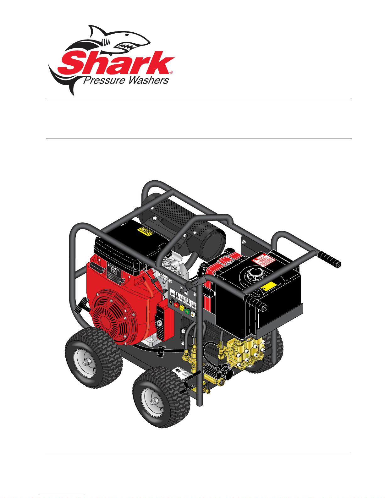
MODEL: BR
OPERATING INSTRUCTION
AND PARTS MANUAL
■ BR-442537 ■ BR-353237 ■ BR-373537
■ BR-404027 ■ BR-455037E ■ BR-343087E
For technical assistance or the SHARK dealer nearest you, call 1-800-771-1881
or visit our website at www.shark-pw.com
97-723
Page 2

Page 3

Important Safety Information ................................................................4-5
Component Identifi cation Small...............................................................6
Component Identifi cation Large...............................................................7
Assembly Instructions..............................................................................8
Operating Instructions ........................................................................9-10
Applying Detergent and General Operating Techniques........................11
Shut Down and Clean-Up......................................................................12
Storage..................................................................................................12
Troubleshooting................................................................................13-14
Preventative Maintenance .....................................................................15
Oil Change Record................................................................................15
Exploded View - Large...........................................................................16
Exploded View Parts List..................................................................17-19
Exploded View - Small...........................................................................20
Exploded View Parts List..................................................................21-22
Hose and Spray Gun Assembly.............................................................23
Specifi cations....................................................................................24-25
Warranty
CONTENTS
Model Number _________________________________
Serial Number _________________________________
Date of Purchase _______________________________
The model and serial numbers will be found on a decal at tached
to the pressure washer. You should record both serial number and
date of purchase and keep in a safe place for future ref er ence.
3
96-718, 97-721, 97-723 • REV. 8/05a
Page 4
INTRODUCTION & IMPORTANT SAFETY INFORMATION
Thank you for purchasing a this pressure washer.
All in for ma tion in this man u al is based on the lat est
prod uct in for ma tion avail able at the time of print ing.
Manufacturer reserves the right to make changes at
any time with out incurring any obligation.
Owner/User Responsibility:
The owner and/or user must hav e an un der stand ing of
PRESSURE W ASHER
the manufacturer’ s operating instructions and warnings
be fore us ing this pressure washer. W arning in for ma tion
should be emphasized and understood. If the op er a tor
is not fl uent in En glish, the manufacturer’s in struc tions
and warnings shall be read to and dis cussed with
the op er a tor in the operator’s native lan guage by the
pur chas er/owner, making sure that the operator com pre hends its contents.
Owner and/or user must study and maintain for fu ture
ref er ence the man u fac tur ers’ instructions.
OPERATOR’S MANUAL
The operator must know how to stop the machine
quick ly and un der stand the operation of all controls.
Never per mit any one to op er ate the engine without
proper in struc tions.
This manual should be considered a permanent
part of the machine and should remain with it if
ma chine is resold.
When ordering parts, please specify model and
serial number.
MPORTANT SAFETY
I
INFORMATION
CAUTION
READ OPERATOR’S
MANUAL THOR OUGH LY
PRI OR TO USE.
2.All installations must com ply with local codes. Con tact your elec tri cian, plumb er, utility com pa ny or the
sell ing dis trib u tor for spe cifi c details.
3. This machine has been pro vid ed with Warn ing and
In struc tion decals for the safety of the operator. If
these decals are removed or be come damaged
they should be re placed. Contact your dealer for
re place ment de cals.
CAUTION: To reduce the risk of
in ju ry, read op er at ing in struc tions care ful ly be fore us ing.
1. Read the own er's man u al
thor ough ly. Fail ure to fol low
in struc tions could cause mal func tion of machine and re sult
in death, se ri ous bodily injury
and/or prop er ty dam age.
CAUTION
CAUTION: Risk of as phyx i a tion
— Use this product only in a well
ven ti lat ed area.
4. Avoid installing ma chines in
small areas or near ex haust
RISK OF
ASPHYXIATION.
USE ONLY IN A WELL
VENTILATED AREA.
fans. Ex haust con tains poi son ous car bon mon ox ide gas;
ex po sure may cause loss of
con scious ness and may lead to
death. It also con tains chemicals known, in cer tain
quan ti ties, to cause can cer, birth de fects or oth er
re pro duc tive harm.
WARNING
WARNING: Flammable liquids
can create fumes which can
ig nite caus ing prop er ty damage
or se vere in ju ry.
WARNING: Risk of fi re — Do not
add fuel when the prod uct is
RISK OF FIRE.
DO NOT ADD FUEL
WHEN OPERATING
MACHINE.
operating.
WARNING: Risk of explosion —
Do not spray fl am ma ble liq uids.
5.Do not place ma chine near fl ammable ob jects as
the en gine is hot.
6. Allow engine to cool for 2 minutes before re fu el ing. If
any fuel is spilled, make sure the area is dry be fore
test ing the spar k plug or start ing the en gine. (Fire
and/or ex plo sion may oc cur if this is not done.)
When refueling gasoline engines on mo bile or
por ta ble equipment, make sure to refuel:
a. outdoors;
b. with the engine on the equip ment stopped;
c. with no source of ig ni tion within 10 feet of the
dis pens ing point; and
d. with an allowance made for ex pan sion of the
fuel should the equip ment be exposed to a
high er am bi ent tem per a ture.
In an overfi lling or spillage situation, additional pre-
cau tions are nec es sary to en sure that the sit u a tion
is han dled in a safe man ner.
WARNING
WARNING: High pressure stream
of water that this equip ment can
pro duce can pierce skin and its
un der ly ing tis sues, lead ing to
se ri ous in ju ry and pos si ble
am pu ta tion.
HIGH PRESSURE
SPRAY CAN PIERCE
SKIN AND TIS SUES.
4
96-718, 97-721, 97-723 • REV. 8/05a
Page 5
INTRODUCTION & IMPORTANT SAFETY INFORMATION
PRESSURE WASHER
WARNING
WARNING: High pressure spray
can cause paint chips or other
par ti cles to become air borne and
fl y at high speeds. To avoid per son al in ju ry, eye safe ty de vic es
must be worn.
PROTECTIVE
EYEWEAR AND
CLOTH ING MUST
BE WORN.
7. Protective cloth ing and foot
protection must be worn when
using this equipment.
8. High pres sure de vel oped by these machines will
cause per son al in ju r y or equip ment dam age. Use
cau tion when op er at ing. Do not di rect dis charge
stream at peo ple, or se vere in ju ry or death will
re sult.
9. Never make ad just ments on ma chine while in
operation.
10. Do not block or tie spray gun in open position.
11. Do not place hands or feet on non-insulated areas
of the pres sure washer when starting gas o line
engine.
12. When applying detergents, fol low the safety rules
on the de ter gent label.
13. Use detergent from a covered D.O.T. approved
con tain er.
14. Cleaning area should be provided with adequate
slopes and drainage. This will reduce the pos si bil i ty
of a fall due to slippery surface.
15. The best in sur ance against an accident is pre cau tion and knowl edge of the ma chine.
16. Manufacturer will not be liable for any changes
made to our stan dard ma chines, or any com po nents not pur chased from the manufacturer.
17. Read engine safety in struc tions provided.
WARNING
WARNING: Keep water spray
away from electrical wir ing or
fa tal elec tric shock may re sult.
18. Never run pump dry or leave
spray gun closed long er than
5 min utes.
KEEP WA TER SPRAY
AWAY FROM
ELECTRICAL WIRING.
19. Do not allow children to op er ate the pressure wash er at
any time.
20. Do not allow machine to run un at tend ed.
21. Inlet water sup ply must be cold and clean fresh
water.
CAU TION: Spray gun kicks back – Hold with both
hands.
CAU TION: Risk of injury – Dis con nect battery
ground ter mi nal be fore servicing.
OPERATOR’S MAN U AL
5
96-718, 97-721, 97-723 • REV. 8/05a
Page 6
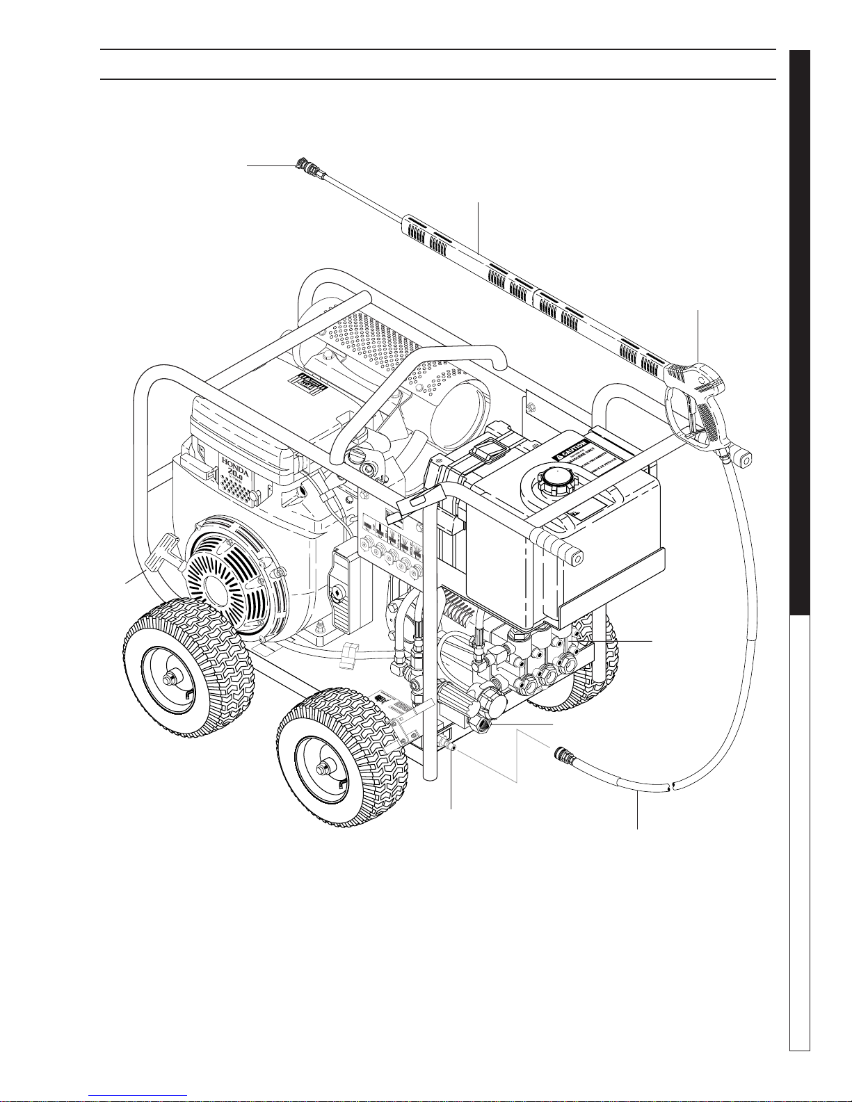
COMPONENT IDENTIFICATION — SMALL MODELS
Nozzle
Wand
PRESSURE W ASHER
OPERATOR’S MANUAL
Spray Gun
Starter
Grip
Pump
High Pressure
Hose
Pump — Develops high pressure.
Starter Grip— Used for starting the engine man u al ly.
Spray Gun — Controls the application of water and
de ter gent onto cleaning surface with trigger device.
In cludes safe ty latch.
Detergent Injector — Allows you to siphon and mix
detergents (not shown).
6
High Pressure
Discharge
Wand — Must be connected to the spray gun.
High Pressure Hose — Connect one end to water
pump dis charge nipple and the other end to spray
gun.
Note: If trigger on spray gun is released for more
than 2 minutes, water will leak from valve. Warm
water will dis charge from pump protector onto fl oor.
This sys tem pre vents internal pump dam age.
96-718, 97-721, 97-723 • REV. 8/05a
Water Inlet
Page 7
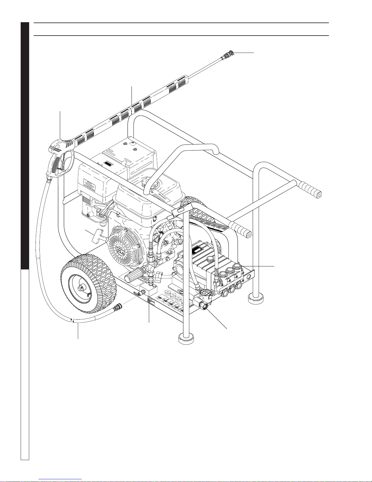
COMPONENT IDENTIFICATION — LARGE MODELS
Nozzle
Wand
Spray Gun
PRESSURE WASHER
OPERATOR’S MAN U AL
Starter
Grip
High Pressure
Discharge
Pump
Water Inlet
High Pressure
Hose
7
96-718, 97-721, 97-723 • REV. 8/05a
Page 8
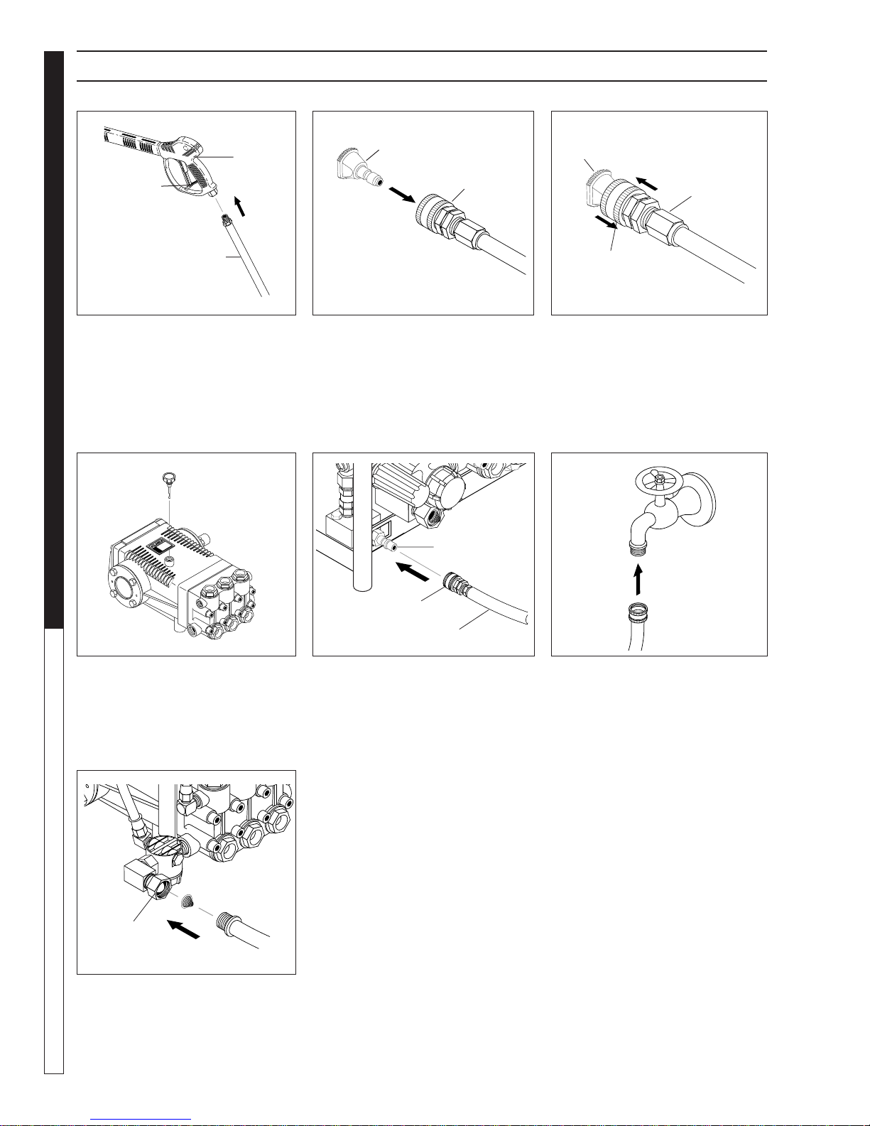
ASSEMBLY INSTRUCTIONS
Spray
Gun
Safety
Latch
PRESSURE W ASHER
High Pressure
Hose
STEP 1: Attach the high pres sure
hose to the spray gun using tefl on
tape on hose threads.
OPERATOR’S MANUAL
Dipstick
Pressure
Nozzle
Wand
Coupler
STEP 2: Pull the spring-load ed col-
lar of the wand coupler back to in sert
your choice of pres sure noz zle.
Discharge
Nipple
Pressure
Nozzle
Wand
Coupler
Wand
Collar
STEP 3: Release the coupler col lar
and push the nozzle until the collar
clicks. Pull the nozzle to make sure
it is seat ed properly.
Cold
Water
Source
STEP 4: Remove shipping cap and
install oil dipstick. Check pump oil
level by using dipstick or observe
oil level in oil window (if equipped).
Use 30 wt. non detergent oil.
Pump
Water Inlet
STEP 7: Check inlet fi lters, remove
debris, then connect garden hose
to pump wa ter in let. CAU TION: Do
not run the pump with out wa ter or
pump dam age will result.
8
Garden
Hose
Coupler Collar
High Pressure Hose
STEP 5: Connect the high pres sure
hose to the pump discharge nipple.
Push coupler collar forward until
se cure.
96-718, 97-721, 97-723 • REV. 8/05a
Garden
Hose
STEP 6: Connect garden hose to
the cold water source.
Page 9
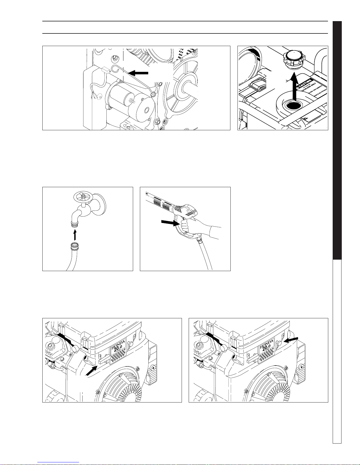
OPERATING INSTRUCTIONS
Engine
Oil
Dipstick
PRESSURE WASHER
Gas
Tank
OPERATOR’S MAN U AL
STEP 1: Check engine oil level. Oil level should be level with the bottom
of the oil fi ller neck. Be sure the ma chine is level when checking the oil
level. (Refer to the en gine's op er at ing manual included with machine.) W e
rec om mend that the oil be changed after the fi rst 5 hours of use, then once
every 50 hours. Note: Im prop er oil levels will cause low oil sensor to shut
off engine. IMPORTANT! Do not run engine with high or low oil le vels
as this will cause engine damage.
Cold
Water
Source
Garden
Hose
STEP 3: Connect garden hose
to the cold water source and turn
wa ter on completely. Never use
hot wa ter.
STEP 4: Tr igger the spray gun to
elim i nate trapped air then wait for a
steady fl ow of water to emerge from
the spray noz zle.
STEP 2: Fill gas tank with un lead ed gasoline. Do not use leaded
gas o line.
Fuel
Valve
STEP 5: Rotate the fuel shut-off valve to the "On" po-
si tion. Slide the fuel valve lever to the "ON" position.
When the engine is not in use, leave the fuel valve in
the "OFF" position.
STEP 6: Pull the choke knob out to the "Chok e" po si tion
(on a warm engine, when in the run po si tion, leave the
choke knob in). Push the choke knob to the "Closed"
po si tion. T o restart a warm engine, leave the chok e knob
in the "Open" position.
96-718, 97-721, 97-723 • REV. 8/05a
Choke
Knob
9
Page 10

OPERATING INSTRUCTIONS (CON'T)
On-Off
PRESSURE W ASHER
STEP 7: Turn the engine switch to "ON" position. STEP 8: Pull the starter grip. If the engine f ails to start
OPERATOR’S MANUAL
NOZZLES
Switch
after 2 pulls, squeeze the trigger gun to release pres sure
and repeat step. Return start er gently. After the en gine
warms up enough to run smoothly, move choke to run
position and throt tle to fast position.
CAUTION: Small engines may kick back. Do not hold
pull starter grip tightly in hand.
The fi ve color-coded quick con nect
noz zles provide a wide array of spray
widths from 0° to 45° and are easily accessible when placed in the con ve nient
rubber nozzle holder, which is provided
on the front of the ma chine.
NOTE: For a more gentle rinse, se lect
the white 40° or green 25° noz zle. To
scour the surface, select the yello w 15°
or red 0° nozzle. To apply de ter gent
select the black noz zle.
Safety
Latch
WARNING! Never replace
noz zles without engaging the
safe ty latch on the spray gun
trig ger.
10
96-718, 97-721, 97-723 • REV. 8/05a
Page 11

PRESSURE WASHER
APPLYING DETERGENT
AND GENERAL CLEANING
TECHNIQUES
WARNING
STEP 1: Connect detergent in jec tor to discharge nipple
on machine. Connect high pressure hose to in jec tor
with quick coupler . (Chec k to make sure locking cou pler
sleeves are in proper position before ap ply ing wa ter
pres sure).
Discharge
Nipple
Detergent
Injector
Quick Coupler
High
Pressure
Hose
gun engaged, se cure black soap noz zle into quick cou pler.
NOTE: De ter gent can not be ap plied using red, yellow ,
green or white noz zles.
IMPORT ANT : You must fl ush the detergent in jec tion
sys tem after each use by plac ing the suction hose
into a buck et of clean wa ter, then run the pres sure
wash er in low pres sure for 1-2 minutes.
WARNING: Some de ter gents
may be harm ful if in haled or
in gest ed, caus ing severe nau sea, fainting or poi son ing. The
harm ful el e ments may cause
prop er ty dam age or severe
injury.
Filter
Soap
Nozzle
STEP 2: Use detergent de signed
spe cifi cal ly for pres sure washers.
House hold de ter gents could dam age the pump. Pre pare detergent
so lu tion as required by the man u fac tur er . Fill a container with pres sure washer de ter gent. Place the
fi lter end of detergent suction hose
into the de ter gent container.
STEP 3: With saf ety latch on spray
STEP 4: With the engine run-
ning, pull tr ig ger to op er ate ma chine. Liq uid detergent is drawn
into the ma chine and mixed with
water. Apply de ter gent to work
area. Do not al low de ter gent to
dry on sur face.
96-718, 97-721, 97-723 • REV. 8/05a
THERMAL PUMP
PROTECTION
If you run the engine on your pres sure wash er for 3-5
min utes with out pressing the trig ger on the spray gun,
cir cu lat ing water in the pump can reach high tem per a tures. When the water reach es this tem per a ture, the
pump pro tec tor engages and cools the pump by dis charg ing the warm water onto the ground. This ther mal
de vice pre vents internal dam age to the pump.
CLEANING TIPS
Pre-rinse clean ing surface with fresh water. Place de ter gent suc tion tube di rect ly into clean ing solution and
ap ply to sur face at low pressure (for best re sults, lim it
your work area to sec tions ap prox i mate ly 6 feet square
and al ways ap ply de ter gent from bottom to top). Allow
de ter gent to re main on sur face 1-3 min utes. Do not al low de ter gent to dry on sur face. If sur face appears to
be drying, sim ply wet down sur face with fresh water. If
need ed, use br ush to re move stub bor n dirt. Rinse at
high pres sure from top to bottom in an e v en sweep ing
mo tion keep ing the spray nozzle ap prox i mate ly 1 foot
from clean ing sur f ace. Use o ver lap ping strokes as you
clean and rinse any sur face . For best surface clean ing
action spray at a slight an gle.
Recommendations:
• Before cleaning any surface, an inconspicuous
area should be cleaned to test spray pattern and
dis tance for maximum cleaning results.
• If painted surfaces are peeling or chipping, use
ex treme caution as pressure washer may re move
the loose paint from the surface.
• Keep the spray nozzle a safe distance from the
sur face you plan to clean. High pressure w ash a
small area, then check the surface f or damage. If
no dam age is found, continue to pressure wash ing.
CAUTION - Never use:
• Bleach, chlorine products and other corrosive
chem i cals
• Liquids containing solvents (i.e., paint thinners,
gas o line, oils)
• Tri-sodium phosphate products
• Ammonia products
• Acid-based products
These chemicals will harm the machine and will dam age the surface
being cleaned.
RINSING
It will take a few sec onds for the de ter gent to clear.
Apply safe ty latch to spray gun. Re move black soap
noz zle from the quick cou pler. Select and in stall the
de sired high pres sure noz zle. NOTE: You can also stop
de ter gent from fl ow ing by sim ply re mov ing de ter gent
si phon hose from bottle.
OPERATOR’S MAN U AL
11
Page 12

SHUTTING
DOWN
AND CLEAN-UP
On-Off
Switch
STEP 1: Remove detergent suc tion
PRESSURE W ASHER
tube from container and insert into
one gallon of fresh water. Slide noz zle
for ward for low pressure or to con nect
black detergent nozzle. Pull trig ger on
spray gun and si phon water for one
minute.
OPERATOR’S MANUAL
Water
Inlet
STEP 4: Press
trig ger to re lease
wa ter pres sure.
CAUTION: Al wa ys store y our pressure washer in a
lo ca tion where the temperature will not fall be low
32°F (0°C). The pump in this machine is sus cep ti ble
to permanent dam age if fro zen. FREEZE DAM AGE
IS NOT COV ERED BY WARRANTY.
1. Stop the pressure washer, squeez e spray gun trig ger to release pressure.
2.
Detach water supply hose and high pressure hose.
3. Turn on the machine for a few seconds, until re main ing water exits. Turn engine off im me di ate ly.
4. Drain the gas and oil from the engine.
5.
Do not allow high pressure hose to become kinked.
6. Store the machine and accessories in a room which
does not reach freezing temperatures.
CAUTION: Fail ure to follow the abo ve di rec tions will
result in dam age to your pres sure washer.
When the pres sure washer is not being operated or is
be ing stored for more than one month, follow these
in struc tions:
1. Replenish engine oil to up per level.
2. Drain gas o line from fuel tank, fuel line, fuel valve
and carburetor.
3. Pour about one teaspoon of engine oil through
the spark plug hole, pull the starter grip several
12
times and re place the plug. Then pull the starter
STEP 5: Disconnect the garden
hose from the water inlet on the
machine.
STEP 2: Turn engine switch to "OFF"
position.
96-718, 97-721, 97-723 • REV. 8/05a
STEP 6: Disconnect the high
pres sure hose from the discharge nipple.
STORAGE
grip slow ly until you feel increased pressure which
indicates the pis ton is on its compression stroke and
leave it in that position. This closes both the intak e
and ex haust valves to prevent rusting of cylinder.
4. Cover the pressure washer and store in a clean, dry
place that is well ventilated away from open fl ame
or sparks. NOTE: The use of a fuel additive, such
as STA-BIL®, or an equivalent, will minimize the
for mu la tion of fuel deposits during shortage. Such
ad di tives may be added to the gasoline in the fuel
tank of the engine, or to the gasoline in a storage
con tain er.
After Extended Storage
Engine Maintenance
During the winter months, rare atmospheric conditions
may develop which will cause an icing con di tion in the
car bu re tor. If this de vel ops, the engine may run rough,
lose power and may stall. This temporary condition can
be overcome by defl ecting some of the hot air from the
en gine over the carbure tor area. NOTE: Refer to the
en gine man u fac tur er's manual for service and main te nance of the engine.
STEP 3: Turn off water
sup ply.
Discharge
Nipple
Safety
Latch
STEP 7: En gage
the spray gun saf e ty
lock.
CAUTION: Prior to restarting, tha w out any
pos si ble ice from pressure washer hos es,
spray gun or wand.
Page 13

TROUBLESHOOTING
PROBLEM POSSIBLE CAUSE SOLUTION
LOW OPERATING
PRESSURE
FLUCTUATING
PRESSURE
PRESSURE LOW
AFTER PERIOD OF
NORMAL USE
ENGINE WILL NOT
START OR STOPS
WHILE OPERATING
ENGINE IS
OVERLOADED
WATER OR OIL
LEAKING FROM
BOTTOM OF PUMP
PRESENCE OF WATER
IN PUMP OIL
Insuffi cient water supply. Closed
faucet. Inlet hose kinked
Clogged inlet hose strainer Check plumbing system for leaks. Retape
Faulty or misadjusted unloader
valve
Worn packing in pump Call technical support.
Machine has been stored in freez-
ing temperatures.
Slow engine RPM Call technical support.
Worn or dirty pump valves Call technical support.
Nozzle is obstructed Use nozzle wire in accessory kit.
Pump sucking air, inlet hose leak-
ing
Nozzle worn Replace nozzle.
Unloader valve worn Replace unloader valve.
Low oil shutdown Fill engine with oil.
Water in gasoline Drain gas tank; fi ll with clean fuel.
Out of gas Fill fuel tank.
Nozzle partially blocked Clean nozzle.
Excessive pressure from high
engine RPM
A small amount of leaking is
normal
Water sprayed at machine Change oil. Direct spray away from ma-
High humidity in air Check and change oil twice as often.
Piston packing worn. Oil seal
worn
Use larger garden hose; clean inlet water
screen. Open faucet.
leaks with tefl on tape.
Adjust unloader for proper pressure. Install
repair kit when needed. Call technical support.
Thaw out machine completely, including
hose, spray gun and wand.
Check all pump lines and connections.
Adjust engine throttle to lower RPM.
If excessive leaking occurs, call technical
support.
chine.
Call technical support.
PRESSURE WASHER Troubleshooting Guide
13
96-718, 97-721, 97-723 • REV. 8/05a
Page 14

TROUBLESHOOTING
PROBLEM POSSIBLE CAUSE SOLUTION
ENGINE OPERATES
FOR 15 MIN. THEN
STOPS
ENGINE LACKS POWER
ENGINE FALTERS
PRESSURE W ASHER
WATER DRIPPING FROMUNDER PUMP
OIL DRIPPING
WATER LEAKING FROM
PUMP PROTECTOR
OPERATOR’S MANUAL
NO DETERGENT
GARDEN HOSE
CONNECTION LEAKS
SPRA Y W AND LEAKS
PUMP IS NOISY
Not enough gas or engine oil Fill tank with gas. Check oil level.
Vapor lock developed by heat of
day
Obstruction in fuel fi lter Clean or replace fuel fi lter.
Dirty air fi lter Replace air fi lter.
Choke is opened too soon Move choke to halfway position until en-
Piston packing worn Call technical support.
O-Ring plunger retainer worn Call technical support.
Cracked piston Call technical support.
Oil seal worn or damaged Call technical support.
Spray gun closed with machine
running 5 minutes or longer
Excess water supply pressure Place a pressure regulator at end of 50’
Detergent suction tube not properly connected to machine
Detergent is too thick Dilute detergent. For best results, use
Detergent fi lter valve is at lowest
setting
Filter on detergent suction tube is
clogged
Damaged or clogged detergent
suction tube
A high pressure nozzle is attached.
Discharge nozzle is obstructed Blow out or remove debris with fi ne needle.
Loose fi ttings Tighten fi ttings.
Missing/worn rubber washer Insert new washer.
Spray wand not properly attached Slide the spray wand into the gun. Turn the
Broken o-ring Call customer service and order an o-ring.
Pump is sucking air Check that hoses and fi ttings are air tight.
Keep gas tank full to avoid vapor locking.
gine runs smoothly.
Open spray gun or turn off machine.
garden hose.
Check connection.
Rhino detergent.
Set detergent fi lter valve to a higher set-
ting.
Run warm water through fi lter to remove
debris.
Remove obstruction or replace detergent
suction tube.
Replace with black detergent nozzle.
wand collar clockwise onto the spray gun
threads until tight.
Turn off machine and purge pump by
squeezing trigger gun until a steady fl ow of
water emerges through nozzle.
14
96-718, 97-721, 97-723 • REV. 8/05a
Page 15

PREVENTATIVE MAINTENANCE
This pressure washer was produced with the best avail able ma te ri als and quality craftsmanship. However, you
as the own er hav e certain re spon si bil i ties f or the correct care of the equip ment. At ten tion to reg u lar pre ven ta tive
main te nance pro ce dures will as sist in preserving the per for mance of your equipment. Contact your dealer for
main te nance. Regular pre ven ta tive main te nance will add many hours to the lif e of your pres sure washer . Per form
main te nance more often under severe conditions.
PRESSURE WASHER
Pump Oil Inspect
Change
Replace high pressure nozzle
Replace quick connects
Clean water screen/fi lter
Replace HP hose
Grease motor
Daily inspect the oil level
After fi rst 50 hours, then every 500 hours or
annually
Every 6 months
Annually
Weekly
Annually if there is any sign of wear
Every 10,000 hours
OIL CHANGE RECORD
Check pump oil and engine oil level before fi rst use of your new pressure washer.
Estimated Operating
Date Oil Changes
Month/Day/Year
Hours Since Last
Oil Change
Date Oil Changes
Month/Day/Year
OPERATOR’S MAN U AL
Estimated Operating
Hours Since Last
Oil Change
15
96-718, 97-721, 97-723 • REV. 8/05a
Page 16

EXPLODED VIEW - LARGE
PRESSURE W ASHER
OPERATOR’S MANUAL
31
27
88
79
2
43
16
23
8,9
50
343087E,343089E,
404027, 404029
Models
59
18
22
45
40
18
39
45
20
62
42
54
56
4
57
1
12
3
60
55
5
73
57
59
57
37
34
36
35
38
All Models
26
28
16
84
78
33
9
8
50
22
18
65
77
61
19
21
15
Except
32
82
4040
71
10
14
23
73
76
75
44
7
52
13
53
Models
404027,
404029
48
74
29
48
74
49
49
42
48
89
48
74
59
30
74
29
11
86
87
59
74
60
74
48
85
53
59
47
48
71
25
59, 60, 61
60
80
64
46
68
67
66
24
81
59
60
7269
58
70
6
49
48
74
70
72
58
17
51
51
16
96-718, 97-721, 97-723 • REV. 8/05a
Page 17

EXPLODED VIEW PARTS LIST- LARGE
PRESSURE WASHER
ITEM PART NO. DESCRIPTION QTY
1 10-02011 Label, This Tank For Gas Only
(455037E, 455039E, 455034E) 1
10-020090 Label, Diesel (343087E,
343089E) 1
2 10-02025A Label, “Hot/Caliente” w/Arrows 1
3 10-02029 Label, Danger Cool Engine
(455037E, 405039E, 455039E
455034E) 1
4 11-01011 Label, Warning Pictoral(Small) 1
5 11-013 ▲ Label, Logo, Belt Guard
(BR) 1
10-03014 ▲ Label, Logo, Belt Guard
(MP) 1
11-3227 ▲ Label, Logo, Belt Guard
(BD) 1
6 11-0316 Label, Instructions 1
7 10-03008 Label, Nozzle Identifi cation 1
8 2-0051 Nipple, 1/2” JIC, 3/8” Pipe 1
9 2-0079 Swivel, 1/2" JIC Fem,
3/8" Male 1
10 2-010061 Bushing, Rubber, Nitrile (405039E,
455039E, 455034E, 455037E) 1
(343087E, 343089E) 2
11 2-0103 Grommet, Rubber, Nozzle
Holder 5
12 2-011507 Tank, Encore 5 Gal. Tank
(343087E, 343089E, 405039E,
455039E, 455034E) 1
13 2-01167 Cap, Fuel Tank, Plastic (343087E,
343089E, 405039E, 455039E,
455034E, 455037E) 1
14 2-0117 Battery, Box (343087E, 343089E,
405039E, 455039E, 455034E,
455037E) 1
15 2-011700 Plate, Battery Box, Small, Polypro
(343087E, 343089E, 405039E,
455039E, 455034E, 455037E) 1
16 2-0051 Nipple 1/2" JIC x 3/8" Male
(343087E,343089E,404027,
404029) 1
2-00510 Nipple, 1/2" JIC x 3/8" Fem
(405039E, 455034E, 455037E,
455039E) 1
17 2-0155 Fastener, Ratchet, Black Nylon 2
18 2-1062 Elbow, 1/2" JIC x 1/2", 90°
(405039E, 455034E, 455037E
455039E) 2
(343087E, 343089E, 404027,
404029) 1
2-1060 Elbow, 1/2” JIC x 3/8”, 90°
(404027, 404029, 343087E,
343089E) 1
ITEM PART NO. DESCRIPTION QTY
19 2-10942 Swivel, 1/2"MP x 3/4" GHF
w/Strainer 1
20 2-1105 Swivel, 1/2" JIC Fem, Push-On 2
21 2-1923 Strainer, 1/2" PA, Inline Plastic 1
22 2-20022 Nipple, 3/8" Fem, 11,000 PSI”
(405039E, 455039E, 455034E,
455037E) 1
2-2007 Nipple, 3/8" x 3/8" NPT ST Male
(404027, 404029, 343087E,
343089E) 1
23 2-30082 Pump Protector, 1/2" PTP
(405039E, 455039E, 455034E,
455037E) 1
2-300816 Pump Protector, 3/8" (404027,
404029, 343087E, 343089E) 1
24 2-90151 Clamp, Snap-In Wire (343087E,
343089E, 405039E, 455039E,
455034E, 455037E) 2
25 2-9016 Clamp, Round, 0.56 I.D. (405039E,
455039E, 455034E, 455037E) 1
26 4-02047914 Hose, 3/8" x 14", 2 Wire,
Pressure Loop (405039E, 455034E
455037E, 455039E) 1
4-02047714 Hose, 3/8" x 1/4", 2 Wire Pressure
(343087E, 343089E, 404027,
404029) 1
27 4-02100000 Hose, 1/4", Push-On, Fuel Line
(343087E, 343089E, 405039E,
455039E, 455034E, 455037E)
28 4-02110000 Hose, 1/2", Push-On 1.25 ft.
29 4-0307 Wheel & Tire Cmpl, 6" 4
30 4-12803500 Nozzle, SACQMEG, 0003.5, Red
(405039E) 1
4-12803515 Nozzle, SAQCMEG 1503.5, Yellow
(405039E) 1
4-12803525 Nozzle, SAQCMEG, 2503.5,
Green (405039E) 1
4-12803540 Nozzle, SAQCMEG 4003.5, White
(405039E) 1
4.75 ft.
OPERATOR’S MAN U AL
17
96-718, 97-721, 97-723 • REV. 8/05a
Page 18

EXPLODED VIEW PARTS LIST- LARGE
ITEM PART NO. DESCRIPTION QTY
4-12804000 Nozzle, SAQCMEG 0004, Red
(343087E,343089E,404029,
404027,455039E,455034E,
455037E) 1
4-12804015 Nozzle, SAQCMEG 1504, Yellow
(343087E,343089E,404029,
404027,455039E,455034E,
455037E) 1
4-12804025 Nozzle, SAQCMEG 2504, Green
PRESSURE W ASHER
(343087E,343089E,404029,
404027,455039E,455034E,
455037E) 1
4-12804040 Nozzle, SAQCMEG 4004, White
(343087E,343089E,404029,
404027,455039E,455034E,
455037E) 1
4-16540 Nozzle COMPL, QCEM-6540,
Brass (404029, 455039E, 405039E,
343089E, 455034E, 455037E,
OPERATOR’S MANUAL
455037E) 1
31 Engine, See Specifi cations Pages
32 Pump, See Specifi cations Pages
33 Unloader, See Specifi cations Pages
34 Engine Pulley, See Specifi cations Pages
35 Pump Pulley, See Specifi cations Pages
36 Pump Bushing, See Specifi cations Pages
37 Engine Bushing, See Specifi cations Pages
38 Belts, See Specifi cations Pages
39 6-05109 Cable, Battery, 32" Red, 4 Gauge
(343087E, 343089E, 405039E,
455039E, 455034E 455037E) 1
40 6-051092 Cable, Battery, 36" Black, 4 Gauge
(343087E, 343089E, 405039E,
455039E, 455034E, 455037E) 1
41 2-30057 Valve, Shut-Off, 1/4 Turn 1
42 90-1007 Bolt, 5/16" x 1", NC HH
(343087E, 343089E) 6
(405039E, 455039E, 455034E,
455037E) 4
(404027,404029) 2
43 90-1010 Bolt, 5/16" x 1-3/4", NC HH
(404027, 404029) 4
90-1019 Bolt, 3/8" x 1-3/4" (343087E,
343089E) 4
43 90-1020 Bolt, 3/8" x 2", NC, HH (405039E,
455034E, 455037E, 455039E) 4
44 2-010066 Elbow, Fuel Tank, Zinc (343087E,
343089E) 1
45 90-1020 Bolt, 3/8" x 2" NC, HH 2
ITEM PART NO. DESCRIPTION QTY
46 90-102746 Bolt, 1/2" x 5" NC HH Tap (404027,
404029, 405039E, 455039E,
455034E, 455037E) 1
90-102751 Bolt, 1/2" x 3-1/2", NC, HH
(343087E, 343089E) 1
47 90-18012 Screw, 1/4" x 5/8", Phil PH MS
(343087E, 343089E, 405039E,
455034E, 455037E, 455039E) 4
48 90-20041 Collar, 5/8" Bore Shaft 8
49 90-40181 Washer , Nylon Spacer, 0.656 x
1.25 x 0.65 THK 4
50 95-07101216/B Block, Unloader, 3/8" x 3/8"
Brass 1
51 95-07393125 Axle, 5/8" x 31.25" 2
52 95-07104036 Guard, Belt, Rear Steel 1
53 95-07162047 Assy, Weld, Battery Brkt, CW
Cage, Red (343087E, 343089E,
405039E, 455039E, 455037E) 1
95-07162048 Assy, Weld, Battery Brkt, CW
Cage, Black (455034E) 1
95-07162081 Holder, Nozzle (404027
404029) 1
54 95-07162054 Assy, Weld, Cage, CW Red
(BD, BR) 1
95-07162055 Assy. Weld, Cage, CW Black
(MP) 1
55 95-07162045 Guard, Belt, Front, CW Cage,
Black 1
56 95-07162071 Assy, Weld, Slider, CW Cage,
Red (404029, 405039E, 455037E,
455039E, 404027) 1
95-07162072 Assy, Weld, Slider, CW Cage,
Black (455034E) 1
95-07162096 Slider, Assy., Welded, 10HP
Lombardini (343087E,343089E) 1
57 90-1995 Screw, 1/4" x 1/2" BH SOC CS 7
58 90-2000 Nut, 1/4" ESNA, NC 4
59 90-4001 Washer, 5/16" FLAT, SAE (343087E,
343089E, 405039E, 455034E,
455037E, 455039E) 20
(404027,404029) 16
59 90-4002 Washer, 3/8" (404027, 404029) 2
(343087E, 343089E, 405039E,
455034E, 455037E, 455039E) 10
60 90-2001 Nut, 5/16" ESNA, NC (404027,
404029) 10
(343087E, 343089E) 14
(405039E, 455034E, 455037E,
455039E) 12
90-2002 Nut, 3/8" ESNA (404027,
404029) 2
(343087E, 343089E, 405039E,
455034E, 455037E, 455039E) 6
18
96-718, 97-721, 97-723 • REV. 8/05a
Page 19

EXPLODED VIEW PARTS LIST- LARGE
PRESSURE WASHER
ITEM PART NO. DESCRIPTION QTY
61 90-100543 Screw, 5/16"-18 x 3/4" M PH
TRH 4
62 2-1046 Plug, 1/4" Countersunk (405039E,
455034E,455037E, 455039E) 1
63 90-400910 ▲ Washer, 7/16" Lock-Split
Ring 4
90-10343 ▲ Bolt, 10mm x 20mm, HH 4
64 2-01103 Grip, 1" Square Handle 2
65 2-10323 Tee, 1/2", Branch Male 1
66 95-07104828 Bracket, Brake Pad, Red
(BD, BR) 1
95-07164828 Bracket, Brake Pad, Black (MP) 1
67 95-07164829 Linkage, Brake, Black (MP) 1
95-07104829 Linkage, Brake, Red (BD, BR) 1
68 90-3096 Washer, 1/2" Flat 1
69 95-07162065 Handle, Break, CW Cage,
Red (BD, BR) 1
95-07162066 Handle, Break, CW Cage,
Black (MP) 1
70 90-100472 Bolt, Carriage, Zinc, 1/4"-20 x 1.0
PLT 4
71 2-9040 Clamp, Hose, .46-.54 ST
(405039E, 455039E, 455034E,
455037E) 2
(343087E, 343089E) 4
72 90-4000 Washer, 1/4" Flat, SAE 12
73 90-40001 Washer, 1/4" FLAT, SAE, Black,
Zinc 5
74 90-4005 Washer, 5/8" Flat 8
75 1-100534 Valve, Safety Relief, 6000PSI
(405039E, 455039E, 455034E,
455037E) 1
76 2-0031 Elbow, 3/8" Street (405039E,
455039E, 455034E, 455037E) 1
77 2-0006 Nipple, 3/8" Hex Steel (405039E,
455037E, 455039E, 455034E) 1
ITEM PART NO. DESCRIPTION QTY
78 2-0053 Elbow, 1/2" JIC, 3/8", 90° 1
79 77-VHRM4 Muffl er, Honda, GX620/670 Right
(405039E, 455037E, 455039E,
455034E) 1
76-807964 ▲ Muffl er, Exhaust, Briggs 16HP
(404029, 404027) 1
95-07101149 ▲ Guard, Muffl er, Briggs 16HP
(404029, 404027) 1
95-071011491▲ Brace, Muffl er Guard (404029,
404027) 2
76-495518 ▲ Muffl er, Defl ector, Vanguard
(404027, 404029) 1
79-11465813800
▲ Defl ector, Exhaust, Honda
(405039E, 455037E, 455039E,
455034E) 1
80 10-9999 Clear Lexan 1
81 10-08017 Label, Intended For Outdoor
Use 1
82 4-02100000 Hose, 1/4 Push-On (343087E,
343089E) 7.66 ft.
83 2-00471 Plug, 1/8" Square Head, Black
(343087E, 343089E, 405039E,
455037E,455039E, 455034E) 1
84 2-1100 Adaptor, 1/2 x 1/2 (455037E,
343087E, 404027, 404029,
455039E, 343089E, 455034E) 1
85 90-19980 Screw, 1/4" x 1" (405039E,
455034E, 455037E, 455039E) 2
86 90-40001 Washer, 1/4" Flat, SAE, Black
(405039E, 455034E, 455037E,
455039E) 2
87 90-2000 Nut, 1/4" ESNA (405039E,
455034E, 455037E, 455039E) 2
88 95-07162057 Bracket, Regulator 1
89 9.800-049.0 Label, Manufacturer's Cleaning
Solution 1
▲ Not Shown
OPERATOR’S MAN U AL
19
96-718, 97-721, 97-723 • REV. 8/05a
Page 20

EXPLODED VIEW - SMALL
PRESSURE W ASHER
OPERATOR’S MANUAL
11
51
10
5
Model
442539
55
7
15
41
56
56
48
40
43
33
31
14
41
38
9
56
24
30
23
37
56
9
18
50
16
34
53
22
35
57
1
29
2
37
45
9
37
24
9
23
4
3
18
25
21
50
32
11
26
31
10
36
21
19
17
20
6
46
58
54
45
42
43
27
43
49
20
28
12
8
13
47
38
96-718, 97-721, 97-723 • REV. 8/05a
52
44
49
43
27
39
Page 21

EXPLODED VIEW PARTS LIST- SMALL
PRESSURE WASHER
ITEM PART NO. DESCRIPTION QTY
1 10-02025A Label, "Hot/Caliente" w/Arrows
Warning 1
2 10-02029 Label, Danger Cool Engine 1
3 10-08017 Label, Intended For Outdoor Use1
4 10-9999 Label, Clear Lexan,
2-1/4" x 4-1/2" 1
5 11-01011 Label, Warning, Pictoral, Small 1
6 11-0316 Label, Instructions 1
7 10-0623 Label, Belt Guard, MP (353234,
373534, 442534) 1
11-32289 La bel, Belt Guard, BD (353239,
373539) 1
11-3229 La bel, Belt Guard, BR (442537,
353237,373537) 1
8 10-03008 Label, Nozzle Identifi cation 1
9 2-0051 Nipple, 1/2" JIC, 3/8" Pipe 2
10 2-0053 Elbow, 1/2" JIC, 3/8", 90° 1
11 2-0079 Swivel, 1/2" JIC Fem, 3/8" Male 1
12 2-0103 Grommet, Rubber, Nozzle
Holder 5
13 2-01041 Pad, Soft Rubber, 50 Duro 2
14 2-01103 Grip, 1" Square, Handle 2
15 2-0117200 Belt Guard, CW 1
16 2-0155 Fastener, Ratchet, Black Nylon 2
17 2-10323 Elbow, 1/2" Street, Brass 1
18 2-1060 Elbow, 1/2" JIC x 3/8", 90° 1
19 2-1062 Elbow, 1/2" JIC x 1/2", 90° 1
20 2-10942 Swivel, 1/2" MP x 3/4" GHF
w/Strainer 1
21 2-1105 Swivel, 1/2" JIC Fem, Push-On 2
22 2-1923 Strainer, 1/2" PA, Inline Plastic 1
23 2-2007 Nipple, 3/8" x 3/8" NPT ST
Male 1
24 2-300816 Pump Protector, 3/8" PTP 1
25 4-02047720 Hose, 3/8" x 20", 2 Wire,
Pressure Loop 1
26 4-02110000 Hose, 1/2", Push-On 1.25 ft.
27 4-0307 Wheel & Tire Assy, 6" Steel Rim
w/Tube 2
28 4-12804000 Nozzle, SAQCMEG 0004, Red
(353239,373539,353237,
373534,353234,373537) 1
4-12804015 Noz zle, SAQCMEG 1504, Yellow
(353239,373539,353237,
373534,353234,373537) 1
4-12804025 Nozzle, SAQCMEG 2504, Green
(353239,373539,353237,
373534,353234,373537) 1
4-12804040 Nozzle, SAQCMEG 4004, White
(353239,373539,353237,373534,
353234,373537 ) 1
96-718, 97-721, 97-723 • REV. 8/05a
ITEM PART NO. DESCRIPTION QTY
28 4-12805500 Nozzle, SAQCMEG 0005.5, Red
(442534,442537) 1
4-12805515 Nozzle, SAQCMEG 1505.5, Yellow
(442534,442537) 1
4-12805525 Nozzle, SAQCMEG 2505.5, Green
(442534,442537) 1
4-12805540 Nozzle, SAQCMEG 4005.5, White
(442534,442537) 1
4-16540 Nozzle, COMPL, QCEM-6540,
Brass (BD383239,BD373539,
BD442539) 1
29 Engine, See Specifi cations Pages
30 Pump, See Specifi cations Pages
31 Unloader, See Specifi cations Pages
32 Engine Pulley, See Specifi cations Pages
33 Pump Pulley, See Specifi cations Pages
34 Engine Bushing, See Specifi cations Pages
35 Pump Bushing, See Specifi cations Pages
36 Belt, See Specifi cations Pages
37 90-1020 Bolt, 3/8" x 2" NCHH 6
38 90-1018 Bolt, 3/8" x 1-1/2", NC HH 2
39 90-102751 Bolt, 1/2" x 3-1/2", NC HH 1
40 90-10343 Bolt, 10mm x 20mm, HH 4
41 90-19710 Screw, 1/4" x 3/4" HH NC,
Whiz Loc 3
42 90-2002 Nut, 3/8" ESNA, NC 4
43 90-20041 Collar, 5/8" Bore Shaft 3010 4
44 90-3096 Washer, 1/2" Flat 1
45 90-4002 Washer, 3/8" Flat, SAE 8
46 90-4002 Washer, 3/8" SAE, Flat 2
47 90-40125 Washer, 3/8" x 1" 2
48 90-400910 Washer, 7/16", Lock Split Ring 4
49 90-40181 Washer, Nylon Spacer, 0.656" x
1.25" x 0.65" Thick 2
50
Brass 1
51 95-07104001 Slider, Pump/Belt Guard Mount,
Red (BD, BR) 1
95-07104033 Slider, Pump/Belt Guard Mount,
Black (MP) 1
52 95-07104723 Axle, 5/8" x 27.80 L 1
53 95-07162004 Assy, Weld, CW Cage, Small
Red (BD, BR) 1
95-07162005 Assy, Weld, CW Cage, Small
Black (MP) 1
54 90-2002 Nut, 3/8" ESNA, NC 2
55 90-2001 Nut, 5/16" ESNA 4
56 90-4001 Washer, 5/16" Flat 7
95-07101216/B
Block, Unloader, 3/8" x 3/8"
OPERATOR’S MAN U AL
21
Page 22

EXPLODED VIEW PARTS LIST- SMALL
ITEM PART NO. DESCRIPTION QTY
57 2-1102 Adapter, 1/2" Female x 3/8" Male
(343089E,442534) 1
2-1100 Adapter, 1/2 x 1/2 (353234, 373534,
353237, 442537, 373539) 1
58 9.800-049.0 Label, Manufacturer's Cleaning
Solution 1
PRESSURE W ASHER
OPERATOR’S MANUAL
22
96-718, 97-721, 97-723 • REV. 8/05a
Page 23

HOSE & SPRAY GUN ASSEMBLY
1, 2
PRESSURE WASHER
9
4
8
10
7
3
6
57
HOSE & SPRAY GUN ASSEMBLY PARTS LIST
ITEM PART NO. DESCRIPTION QTY
1 4-0110331 Wand, Side Grip w/Couplers 47.5"
(373539, 404029, 343089E) 1
4-012192 Spray Gun w/Wand (5000 PSI),
w/Coupler (405039E, 455039E,
455034E, 455037E) 1
4-011143A Wand, SS V.P. Wand, (AL 344)
w/Coupler, w/Soap Nozzle (353234,
373534, 442534) 1
4-0111341A Wand, V.P. w/Coupler & Nozzle,
X-Series (353237, 373537, 404027,
343087E, 442537) 1
2 4-012402 Spray Gun Assy, w/Nipple (373539,
404029, 343089E) 1
4-01246 Spray Gun, Shut-Off, AP 1000
(442537, 353237, 373537, 404027,
343087E) 1
4-01212 Gun, Shut-Off (373534, 353234,
442534) 1
3 4-02033450CHose, 3/8" x 50 ft., 1 Wire, TUFF-
Skin, w/Coupler (442534,
343089E) 1
4-02043450F Hose, 3/8" x 50 ft., 2 Wire, TUFF Skin, w/5800 PSI Coupler
(405039E, 455039E, 455034E,
455037E) 1
4-020650C Hose, 3/8" x 50", 1 Wire, Pressure
Flex, w/Coupler (343087E) 1
96-718, 97-721, 97-723 • REV. 8/05a
1, 2
ITEM PART NO. DESCRIPTION QTY
3 4-020750C Hose, 3/8" x 50 ft., 2 Wire, Pressure
Flex, w/Coupler (353237, 373537,
373539, 404029, 353234,
373534) 1
Blue, w/Coupler (442537,
353237, 343087E) 1
w/Coupler (373537, 404027) 1
4 3-12021 Injector, Detergent, Non-Adj, 3-5
GPM, 0.083 1
3-1208 Injector, SS, Non-Adj,
2.0-4.0GPM, 5500PSI 1
5 2-1904 Strainer, Plastic, 1/4" Hose Barb1
6 4-02080000 Tube, 1/4" x 1/2", Clear Vinyl 6 ft.
7 2-9040 Clamp, Hose, .46-.54 ST 2
8 2-20021 Coupler, 3/8" Female, 11,000 PSI,
Snap-Tite (405039E, 455034E,
455037E, 455039E) 1
9 2-20022 Nipple, 3/8" Fem, 11,000 PSI
(405039E, 455034E, 455037E,
455039E) 1
10 4-011184 Detergent Injector Assy, 3-5 GPM,
0.83" (353239, 373539, 404029,
343089E, 353234, 373534, 353237,
373537, 343087E, 404027,
442537) 1
4-011186 Downstream Injector Assy, 5000 PSI
(405039E, 455039E, 455034E,
455037E) 1
4-02093450BC
4-02073450RC
Hose, 3/8" x 50 ft., 1 Wire
Hose, 3/8" x 50 ft., 2 Wire Blue,
OPERATOR’S MAN U AL
23
Page 24

SPECIFICATIONS
Machine Engine Pulley Engine Bushing Pump Pump Pump Bushing
Model Pulley Desc. Bushing# Desc. Pulley Desc. Bushing# Desc.
373539 5-40503201 2BK32H 5-511100 Hx1" 5-40509001 2BK90H 5-512024 24mm
404029 5-40503601 2BK36H 5-511100 Hx1" 5-40509001 2BK90H 5-512025 25mm
405039E 5-407034 3TB34 5-531112 P2x1" 5-41009001 3BK90H 5-512025 25mm
455039E 5-407034 3TB34 5-531113 P2x1-1/8" 5-41008001 3BK80H 5-512025 25mm
343089E 5-40504001 2BK40H 5-511100 Hx1" 5-40508001 2BK80H 5-5120220 22mm
PRESSURE W ASHER
353234 5-40503201 2BK32H 5-511100 Hx1" 5-40509001 2BK90H 5-512025 25mm
373534 5-40503201 2BK32H 5-511100 Hx1" 5-40509001 2BK90H 5-512025 25mm
455034E 5-407034 3TB34 5-531113 P2x1-1/8" 5-41008001 3BK80H 5-512025 25mm
304037 5-40504001 2BK40H 5-511100 Hx1" 5-40508001 2BK80H 5-512024 24mm
353237 5-40503201 2BK32H 5-511100 Hx1" 5-40509001 2BK90H 5-512024 24mm
OPERATOR’S MANUAL
373537 5-40503201 2BK32H 5-511100 Hx1" 5-40509001 2BK90H 5-512024 24mm
455037E 5-407034 3TB34 5-531113 P2x1-1/8" 5-41008001 3BK80H 5-512025 25mm
442537 5-40503201 2BK32H 5-511100 Hx1" 5-40508001 2BK80H 5-512024 24mm
404027 5-40503401 2BK34H 5-511100 Hx1" 5-40509001 2BK90H 5-512025 25mm
343087E 5-40503201 2BK32H 5-511100 Hx1" 5-40509001 2BK90H 5-512024 24mm
24
96-718, 97-721, 97-723 • REV. 8/05a
Page 25

SPECIFICATIONS
Machine Belt Belt Pump Unloader Engine
Model (QTY) Desc. Part No. Part No. Part No.
373539 5-604039 (2) BX39 5-1220 5-32080 5-010721
404029 5-604042 (2) BX42 5-1808 5-32080 5-0306
405039E 5-604042 (3) BX42 5-1238 5-3014 5-01093
455039E 5-604042 (3) BX42 5-1238 5-3014 5-01094
343089E 5-604042 (2) BX42 5-1803 5-32080 5-0413
353234 5-604039 (2) BX39 5-1724 5-32080 5-0105
373534 5-604039 (2) BX39 5-1724 5-32080 5-010721
455034E 5-604042 (3) BX42 5-1738 5-3014 5-01094
304037 5-604038 (2) BX38 5-1912 5-32080 5-010721
353237 5-604039 (2) BX39 5-1920 5-32080 5-0105
373537 5-604039 (2) BX39 5-1920 5-32080 5-010721
455037E 5-604042 (3) BX42 5-1938 5-3014 5-01094
442537 5-604037 (2) BX37 5-1915 5-32080 5-0105
404027 5-604043 (2) BX43 5-1924 5-32080 5-0306
343087E 5-604042 (2) BX42 5-1920 5-32080 5-0413
PRESSURE WASHER
OPERATOR’S MAN U AL
25
96-718, 97-721, 97-723 • REV. 8/05a
Page 26

Page 27

BR PRESSURE WASH ER
WARRANTY
SHARK LIMITED NEW PRODUCT WARRANTY
PRESSURE W ASHERS
WHAT THIS WARRANTY COVERS
All SHARK PRESSURE WASHERS are warranted by SHARK to the original purchaser to be free from defects in materials
and workmanship under normal use, for the periods specifi ed below. This Limited Warranty is subject to the exclusions shown
below, is calculated from the date of the original purchase, and applies to the original components only. Any parts replaced
under this warranty will assume the remainder of the part’s warranty period. This warranty applies to the original purchaser and
is not transferable.
LIMITED LIFETIME PARTS WARRANTY:
Components manufactured by SHARK, such as frames, handles, and belt guards. Forged brass pump manifold. All heating
coils will have a three year w arranty . Internal components (excluding oil seals) on the oil-end of all pressure washer pumps will
have a seven year warranty.
ONE YEAR PARTS WARRANTY:
All other components, excluding normal wear items as described below, will be warranted for one year on parts. Warranty on
these parts will be for one year regardless of the duration of the original component manufacturer’s part warranty.
WARRANTY PROVIDED BY OTHER MANUFACTURERS:
Motors, generators, and engines, which are warranted by their respective manufacturers, are serviced through these
manufacturers’ local authorized service centers. SHARK cannot provide warranty on these items.
WHAT THIS WARRANTY DOES NOT COVER
This warranty does not cover the following items:
1. Normal wear items, such as nozzles, guns, discharge hoses, wands, quick couplers, seals, fi lters, gaskets, O-rings,
packings, pistons, pump valve assemblies, strainers, belts, brushes, rupture disks, fuses, pump protectors.
2. Damage or malfunctions resulting from accidents, abuse, modifi cations, alterations, incorrect installation, improper
servicing, failure to follow manufacturer’s maintenance instructions, or use of the equipment beyond its stated usage
specifi cations as contained in the operator’s manual.
3. Damage due to freezing, chemical deterioration, scale buildup, rust, corrosion, or thermal expansion.
4. Damage to components from fl uctuations in electrical or water supply.
5. Normal maintenance service, including adjustments, fuel system cleaning, and clearing of obstructions.
6. Transportation to service center, shop labor charges, fi eld labor charges, or freight damage.
WHAT YOU MUST DO TO OBTAIN WARRANTY SERVICE
While not required for warranty service, we request that you register your SHARK pressure washer by returning the completed
registration card. In order to obtain warranty service on items, you must return the product to an Authorized SHARK Dealer,
freight prepaid, with proof of purchase, within the applicable warranty period. If the product is permanently installed, you must
notify your Authorized SHARK Dealer of the defect. The Authorized Dealer will fi le a claim, which must subsequently verify the
defect. In most cases, the part must be returned to SHARK freight prepaid with the claim. For warranty service on components
warranted by other manufacturers, the Authorized Dealer can help you obtain warranty service through these manufacturers’
local authorized service centers.
LIMITATION OF LIABILITY
SHARK’S liability for special, incidental, or consequential damages is expressly disclaimed. In no event shall SHARK’S
liability exceed the purchase price of the product in question. SHARK makes every effort to ensure that all illustrations and
specifi cations are correct, however , these do not imply a w arranty that the product is merchantable or fi t for a particular purpose,
or that the product will actually conform to the illustrations and specifi cations. THE WARRANTY CONTAINED HEREIN IS
IN LIEU OF ALL OTHER WARRANTIES, EXPRESS OR IMPLIED, INCLUDING ANY IMPLIED WARRANTY OF FITNESS
FOR A PARTICULAR PURPOSE. SHARK does not authorize any other party, including authorized Dealers, to make any
representation or promise on behalf of SHARK, or to modify the terms, conditions, or limitations in any way. It is the buyer’s
responsibility to ensure that the installation and use of SHARK products conforms to local codes. While SHARK attempts
to assure that its products meet national codes, it cannot be responsible for how the customer chooses to use or install the
product.
PRESSURE WASHER WARRANTY
SHARK PRESSURE WASHERS
1-800-771-1881 www.shark-pw.com
SHARK BR • 97-723 • REV. 8/05a
Page 28

Form #97-723 • Revised 8/05a • Printed in U.S.A.
 Loading...