

Shark BR-353037, BR-304031, BR-304037, BR-404021, BR-404027 Operating Instructions And Parts Manual
...Page 1
MODEL: BR
OPERATING INSTRUCTION
AND PARTS MANUAL
■ BR-353031 ■ BR-353037 ■ BR-353531 ■ BR-353537 ■ BR-304031
■ BR-304037 ■ BR-404021 ■ BR-404027 ■ BR-405031E ■ BR-405037E
■ BR-503021 ■ BR-503027 ■ BR-505031E ■ BR-505037E
SHARK PRESSURE WASHERS ■ 4275 N.W. Pacific Rim Blvd. ■ Camas, WA 98607 ■ USA
For technical assistance or the Shark Dealer nearest you, call 1-800-771-1881.
Page 2

Page 3

CONTENTS
3
Component Identification ........................................ 4
Introduction ............................................................. 5
Important Safety Information ................................5-6
Assembly Instructions ..........................................6-7
Installation ........................................................... 7-8
Operating Instructions .......................................... 8-9
Washing Procedures............................................... 9
Shutdown Procedures ............................................ 9
Storage ................................................................... 9
Maintenance & Service ......................................... 10
Troubleshooting Guide .......................................... 11
Machine Assembly & Parts List ....................... 12-13
Pump Exploded View ............................................ 14
Pump Exploded View Parts List ............................ 15
Trigger Gun/Wand Assembly & Parts List ........ 16-17
Pump Assembly & Parts List ............................ 18-19
Warranty
SERIAL NUMBER:
DATE PURCHASED:
FOR SALES AND SERVICE, PLEASE CONTACT:
Shark BR Manual • Form 97-6139 • Revised 01/02a
Page 4
4
BR PRESSURE WASHER
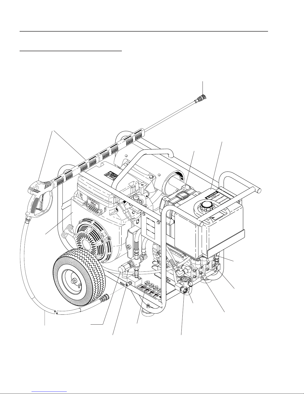
COMPONENT IDENTIFICATION
SPRAY GUN/
WAND
ASSEMBLY
OPERATOR’S MANUAL
PRESSURE NOZZLE
BATTERY
BOX
FUEL
TANK
ENGINE
PRESSURE
HOSE
UNLOADER
VALVE
HOLDERS
PRESSURE
HOSE CONNECTOR
(OUTLET)
NOZZLE
GARDEN
HOSE
CONNECTOR
INLET
WATER
FILTER
RUPTURE
DISK
ASSEMBLY
(5000 PSI
ONLY)
TEMPERATURE
RELIEF VALVE
PUMP
Page 5
BR PRESSURE WASHER
WARNING
WARNING
OPERATOR’S MANUAL
5
INTRODUCTION
Thank you for purchasing a Shark pressure washer.
This manual covers the operation and maintenance of
the BR pressure washers. All information in this manual
is based on the latest product information available at
the time of printing.
Shark reserves the right to make changes at any time
without incurring any obligation.
The BR Series was designed for maximum use
of 8 hours per day, 5 days per week.
Owner/User Responsibility:
The owner and/or user must have an understanding of
the manufacturer’s operating instructions and warnings
before using this Shark pressure washer. Warning information should be emphasized and understood. If the operator is not fluent in English, the manufacturer’s instructions and warnings shall be read to and discussed with
the operator in the operator’s native language by the purchaser/owner, making sure that the operator comprehends its contents.
Owner and/or user must study and maintain for future
reference the manufacturers’ instructions.
The operator must know how to stop the machine quickly
and understand the operation of all controls. Never permit anyone to operate the engine without proper instructions.
This manual should be considered a permanent
part of the machine and should remain with it if
machine is resold.
When ordering parts, please specify model and
serial number.
IMPORTANT SAFETY
INFORMATION
CAUTION
READ OPERATOR’S
MANUAL THOROUGHLY
PRIOR TO USE.
2. All installations must comply with local codes. Contact your electrician, plumber, utility company or the
selling distributor for specific details.
CAUTION: To reduce the risk of
injury, read operating instructions
carefully before using.
1. Read the owner's manual thoroughly. Failure to follow instructions could cause malfunction
of the machine and result in
death, serious bodily injury
and/or property damage.
3. This machine has been provided with Warning and
Instruction decals for the safety of the operator. If
these decals are removed or become damaged they
should be replaced. Contact your dealer for replacement decals.
CAUTION
CAUTION: Risk of asphyxiation —
Use this product only in a well
ventilated area.
4. Avoid installing machines in
small areas or near exhaust
RISK OF
ASPHYXIATION.
USE ONLY IN A WELL
VENTILATED AREA.
death. It also contains chemicals known, in certain
quantities, to cause cancer, birth defects or other
reproductive harm.
fans. Exhaust contains poisonous carbon monoxide gas; exposure may cause loss of consciousness and may lead to
WARNING: Flammable liquids
can create fumes which can ignite
causing property damage or severe injury.
WARNING: Risk of fire — Do not
add fuel when the product is
RISK OF FIRE.
DO NOT ADD FUEL
WHEN OPERATING
MACHINE.
5. Do not place machine near flammable objects as
the engine is hot.
6. Allow engine to cool for 2 minutes before refueling. If
any fuel is spilled, make sure the area is dry before
testing the spark plug or starting the engine. (Fire
and/or explosion may occur if this is not done.)
When refueling gasoline engines on mobile or portable equipment, make sure to refuel:
a. outdoors;
b. with the engine on the equipment stopped;
c. with no source of ignition within 10 feet of the
dispensing point; and
d. with an allowance made for expansion of the fuel
should the equipment be exposed to a higher
ambient temperature.
In an overfilling or spillage situation, additional precautions are necessary to ensure that the situation
is handled in a safe manner.
operating.
WARNING: Risk of explosion —
Do not spray flammable liquids.
Page 6
6
BR PRESSURE WASHER
OPERATOR’S MANUAL
WARNING
WARNING: High pressure stream
of water that this equipment can
produce can pierce skin and its
underlying tissues, leading to serious injury and possible amputation.
HIGH PRESSURE
SPRAY CAN PIERCE
SKIN AND TISSUES.
WARNING
WARNING: High pressure spray
can cause paint chips or other
particles to become airborne and
fly at high speeds. To avoid personal injury, eye safety devices
must be worn.
PROTECTIVE
EYEWEAR AND
CLOTHING MUST
BE WORN.
7. Protective clothing and foot
protection must be worn when
using this equipment.
8. High pressure developed by these machines will
cause personal injury or equipment damage. Use
caution when operating. Do not direct discharge
stream at people, or severe injury or death will result.
9. Never make adjustments on machine while in
operation.
10. Do not block or tie trigger gun in open position.
11. Do not place hands or feet on non-insulated areas of
the pressure washer when starting gasoline engine.
12. When applying detergents, follow the safety rules
on the detergent label.
13. Use detergent from a covered D.O.T. approved container.
14. Cleaning area should be provided with adequate
slopes and drainage. This will reduce the possibility
of a fall due to slippery surface.
15. The best insurance against an accident is precaution and knowledge of the machine.
16. Shark will not be liable for any changes made to our
standard machines, or any components not purchased from Shark.
17. Read engine safety instructions provided.
WARNING: Keep water spray
WARNING
away from electrical wiring or fatal electric shock may result.
18. Never run pump dry or leave
spray gun closed longer than 5
minutes.
KEEP WATER SPRAY
AWAY FROM
ELECTRICAL WIRING.
19. Do not allow children to operate the pressure washer at any
time.
20. Do not allow machine to run unattended.
21. Inlet water supply must be cold and clean fresh
water.
CAUTION: Trigger gun kicks back – Hold with both
hands.
CAUTION: Risk of injury – Disconnect battery ground
terminal before servicing.
ASSEMBLY INSTRUCTIONS
Unpacking
Unpack carefully. Wear safety glasses or goggles while
unpacking, assembling, or operating pressure washer.
If there are missing components or hidden damage, immediately contact carrier concerning discrepancies.
Parts Included
• Pressure Washer
• Pressure Hose
• Wand
• Trigger Gun
• Operater's Manual
• Gasoline Engine Manual
• Pressure Nozzle (4 ea.)
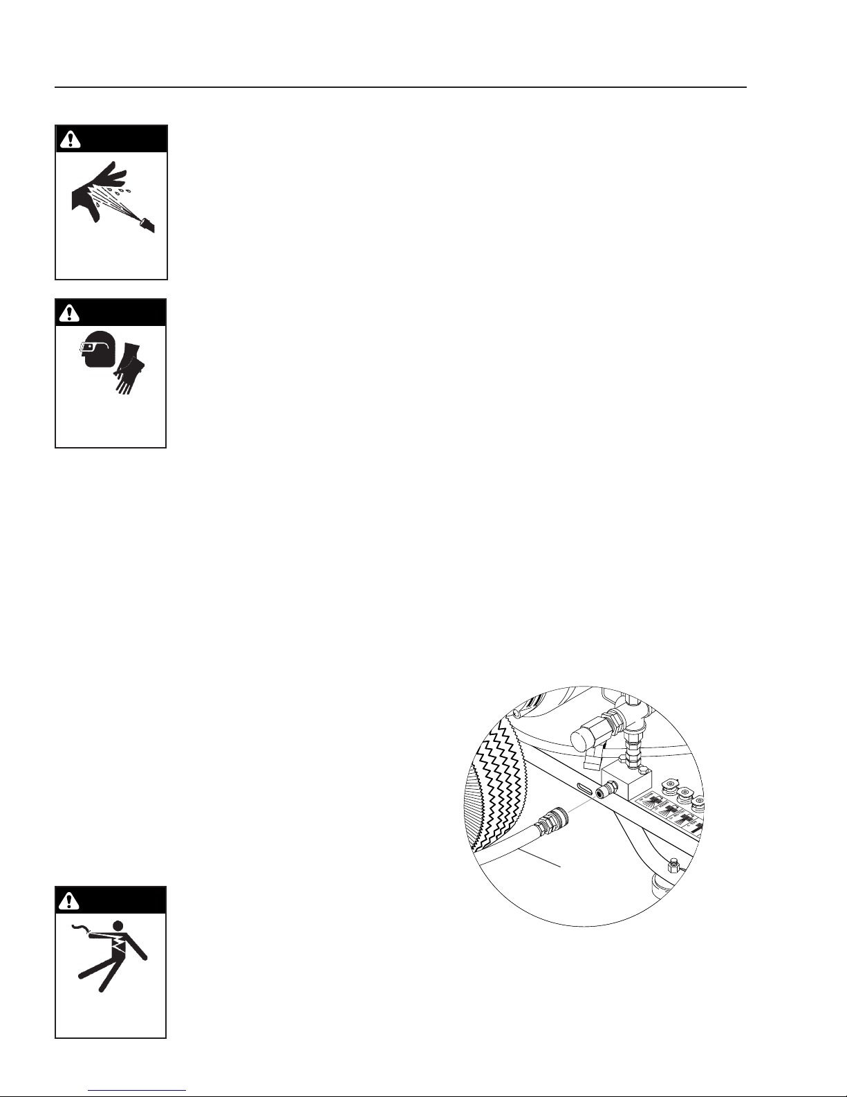
Pressure Hose, Trigger Gun and Wand
1. Install the pressure hose on the pressure washer
as shown in picture below.
PRESSURE
HOSE
Page 7
BR PRESSURE WASHER
OPERATOR’S MANUAL
7
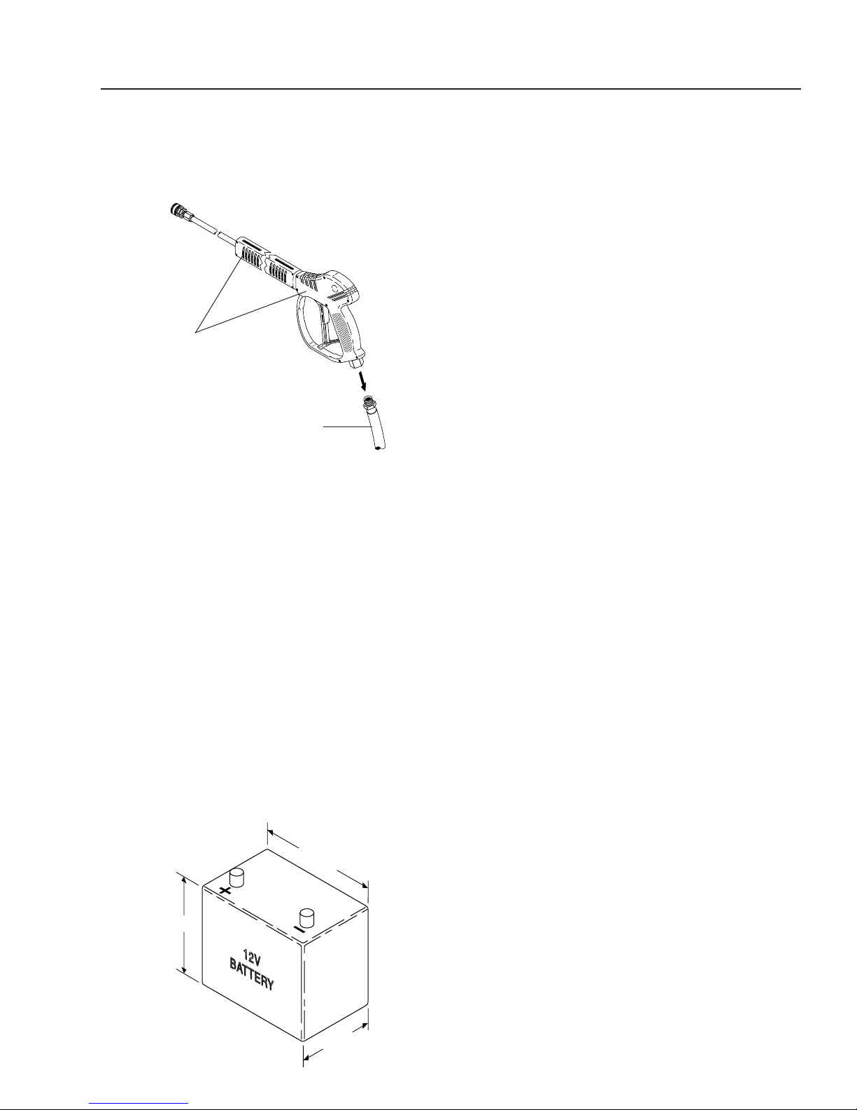
2. Assemble wand components as shown in the picture below.
NOTE: The pressure nozzle is not to be installed at
this time.
TRIGGER GUN/
WAND
ASSEMBLY
PRESSURE
HOSE
3. Make sure all plumbing connections are tight.
Battery
WARNING: Wear eye, hand and skin protection when
handling or connecting battery.
WARNING: Batteries generate explosive gases during
normal battery operation. DO NOT expose the battery
to flame or sparks as these gases may ignite.
WARNING: Battery fluid is highly acidic. If battery fluid
contacts skin or clothing, wash immediately with soap
and water. If battery fluid enters eye, immediately flood
eye with running cold water for at least 15 minutes
and get immediate medical attention.
NOTE: The battery must be capable of accepting ring
terminals.
1. Place battery in battery box (battery not included). Use
a group U1, 12 volt, 30 amp hour battery (garden tractor battery). Select a battery similar to the one in the
picture below for proper fit and installation.
8.00"
6.25"
2. To reduce the possibility of sparking attach the
battery cables in the following order. First attach the
positive battery cable (red) to the positive “+” terminal of battery. Next, attach the negative battery cable
(black) to the negative “—” terminal of the battery.
To disconnect the battery remove the cables in the
opposite order as installed. Install battery box cover
and fasten in place.
INSTALLATION
Getting Started
IMPORTANT: Proper initial installation of equipment
will assure more satisfactory performance, longer
service life, and lower maintenance cost.
IMPORTANT: The use of a backflow preventer on the
water supply hose is recommended and may be
required by local codes.
The pressure washer should be run on a level surface
where it is not readily influenced by outside sources such
as strong winds, freezing temperatures, rain, etc. The
pressure washer should be located to assure easy access for filling of fluids, adjustments and maintenance.
Normal precautions should be taken by the operator to
prevent moisture from reaching the pressure washer.
It is recommended that a partition be made between the
wash area and the pressure washer to prevent direct
spray from the wand coming in contact with the pressure washer. Moisture reaching this equipment will reduce the pressure washer’s life. All installations should
comply with local codes covering such installations.
Venting
DANGER: Do not run machine indoors or in an
enclosed area, as engine exhaust fumes may be hazardous to your health.
DANGER: Do not operate machine in areas where
flammable vapors (gasoline, solvents, etc.) may be
present, as this machine may ignite the vapors.
CAUTION: All venting must be in accordance with
applicable federal and state laws, and local ordinances. Consult local contractors.
If the pressure washer is to be used in an enclosed area,
a flue must be installed to vent engine exhaust to the
outside atmosphere. When selecting the location for operation, beware of poorly ventilated locations or areas
where exhaust fans may cause an insufficient supply of
oxygen. Proper combustion can only be obtained when
there is a sufficient supply of oxygen available for the
amount of fuel being burned. If it is necessary to use the
5.25"
Page 8

8
BR PRESSURE WASHER
OPERATOR’S MANUAL
machine in a poorly ventilated area, outside fresh air may
have to be piped to the engine and a fan installed to
bring sufficient air into the machine.
In addition, the pressure washer should never be operated in an enclosed area where high ambient temperatures exist. High ambient temperatures (above 100
can cause engine oil failure and will greatly reduce the
engine’s performance.
o
F)
Gasoline Engine
This gasoline engine is preset for operation at altitudes
below 3000 feet above sea level. If operated at higher
altitudes, it may be necessary to install a high altitude
main jet in the carburetor. Contact an authorized engine
sales and service center for details. It may become necessary to lower PSI to compensate for high altitudes.
OPERATING INSTRUCTIONS
Before Starting
1. Read all manuals provided with this pressure washer.
Become familiar with location and function of all
operating and safety controls.
CAUTION: Check hoses, fittings, wand, and trigger
gun daily for signs of wear, cracks and looseness,
and replace as required.
2. Connect water supply hose to the garden hose connector located on the pump. The water faucet and
supply hose must be capable of providing a minimum of 5.0 gallons per minute (GPM).
3. Fill the engine fuel tank. Do not overfill, fill to the bottom of filler neck only. Use lead free gasoline minimum 85 octane. DO NOT use gasoline containing
methanol. Refer to the provided gasoline engine
manual for additional details.
4. Check pump and engine oil levels.
IMPORTANT: Before installing pressure nozzle on
initial start-up, turn on the water supply and allow
water to run from the end of the wand until clear to
prevent the nozzle from clogging.
IMPORTANT: If the pressure washer has not been
used for an extended period of time, remove the pressure nozzle from the end of the wand and turn on
water supply. Allow water to run from the end of the
wand until clear.
5. Install the proper pressure nozzle for your cleaning
needs on end of wand, refer to the picture below.
PRESSURE
NOZZLE
MANUAL TRIGGER
LOCK
IMPORTANT: The trigger gun provided with this pressure washer is equipped with a manual trigger lock
to prevent accidental operation of the trigger gun.
The trigger lock should be used whenever the trigger gun is not in use.
To Start
IMPORTANT: The water must be turned on before
starting. Running the pump dry will cause damage
and void warranty.
IMPORTANT: Do not allow the machine to run with
trigger of the trigger gun released for more than
10 minutes at any one time or damage to pump may
occur.
1. Turn ON water supply.
2. Hold wand firmly, release trigger of trigger gun.
3. Turn fuel shutoff valve to ON position (if so equipped).
Move choke lever to full choke position (choke may
not be needed on warm engine). Move throttle lever
to full throttle position.
4. Turn key on engine clockwise, hold until engine starts.
DO NOT crank engine for longer than 15 seconds at
any one time or starter damage may occur.
5. When the engine starts, move choke lever until
engine runs smoothly. When engine warms, move
choke lever to no choke position.
Page 9

BR PRESSURE WASHER
WARNING
OPERATOR’S MANUAL
9
NOTE: If the battery charge is too low to start the
engine, the manual rope start may be used. Set the
engine controls the same as for the key start.
NOTE: If engine fails to start, refer to Troubleshooting Guide in this manual.
6. Squeeze trigger of trigger gun and allow air and pressure to purge from system.
WASHING PROCEDURES
DANGER: Do not place hands or fingers in front of
high pressure spray. Bodily injury may result.
WARNING
SOME DETERGENTS
MAY BE HARMFUL IF
INHALED OR
INGESTED.
3. Use the full width of the spray pattern to wash in a
wide path. Overlap spray paths for complete coverage. Wash from side to side, using slow, steady
motions.
4. The nozzle should be 12" to 24" from work, closer
for tough areas. Be careful on painted or delicate
surfaces, the pressure may damage surface if nozzle
is too close.
5. Small parts should be washed in a basket and larger,
lightweight parts should be clamped down so the
pressure does not push them away.
1. Wash from the bottom to the
top, using side to side motions.
o
2. Do not wash at a 90
work (straight at it). This
allows water to splash back at
you and reduces your cleaning
power. Wash at a 30
60o angle to the work. This will
allow the water to splash away
from you and the water will
wash the dirt away faster and
easier.
angle to
o
to
SHUTDOWN PROCEDURES
1. Move throttle lever to idle position.
2. Turn engine ON/OFF switch to the OFF position.
IMPORTANT: Do not use choke lever to stop engine
as damage to engine may occur.
3. Turn fuel shutoff valve to OFF position (if so
equipped).
4. Turn water supply OFF.
5. Squeeze trigger of trigger gun to relieve system pressure.
STORAGE
DANGER: Do not store flammable
liquids (gasoline, diesel fuel, solvents, etc.) near pressure washer,
or in non-ventilated areas.
1. Protect from freezing by storing
in a heated area, or by flushing
RISK OF FIRE.
DO NOT USE WITH
FLAMMABLE
LIQUIDS.
the system with antifreeze, attach a short length of
hose to the garden hose connector located on the
pump. Place the other end of the hose into a container of antifreeze. Start machine and allow to run
until antifreeze flows from the end of the wand.
Squeeze and release the trigger of the trigger gun
several times to antifreeze the unloader system. If
the pressure washer is not to be used for an extended length of time, it is recommended that the
system be flushed with antifreeze for rust protection. Refer to provided gasoline engine manual for
engine storage information.
the system with antifreeze (use
an automotive engine antifreeze or windshield washer
solvent to antifreeze). To flush
Page 10

10
BR PRESSURE WASHER
OPERATOR’S MANUAL
MAINTENANCE
WARNING: Unauthorized machine modification or
use of non-approved replacement parts may cause
personal injury and/or property damage and will void
the manufacturer warranty.
Pump
Lubrication: To lubricate pump, use 30W non-detergent
oil for pump crankcase. Crankcase must be filled to center of sight glass window found on the side of the pump;
refer to the picture below. During the break-in-period,
make sure the oil is changed after the first 25 hours of
operation. After that, replace oil every 3 months or 300
hours, whichever comes first.
OIL FILL /
DIPSTICK
Gasoline Engine
Refer to the provided gasoline engine manual for recommended maintenance.
Battery
Refer to battery manfacturer’s literature for recom-
mended maintenance.
Unloader Valve
CAUTION: The unloader valve on this pressure
washer has been factory set and sealed and is a field
nonadjustable part. Tampering with the factory setting may cause personal injury and/or property damage, and will void the manufacturer warranty. For
replacement refer to Page 18.
Relief Valve (Rupture Disk)
CAUTION: The relief valve on this pressure washer
has been factory set and sealed and is a field nonadjustable part. Tampering with the factory setting
may cause personal injury and/or property damage,
and will void the manufacturer warranty. For replacement refer to Page 18.
OIL
DRAIN
SIGHT
GLASS
Proper Pump Care:
• DO NOT pump acids.
• DO NOT allow pump to run dry.
• Winterize if storing in freezing temperatures. Refer
to Storage for details.
• Use a water softener on the water system if known
to be high in mineral content.
• Flush the pressure washer system with antifreeze if
storing for an extended period of time. Refer to Stor-
age for details.
Page 11

BR PRESSURE WASHER
OPERATOR’S MANUAL
11
TROUBLESHOOTING GUIDE
SYMPTOM POSSIBLE CAUSES CORRECTIVE ACTION
Gas engine will not run. Out of gas. Replen i s h s upply. Use only recom-
mended fuels. Refer to
under
Operation
Fuel valve closed (if so equipped). Open valve.
Loose spark plug wire. Reconnect.
Before Starting
.
Pressure washer runs
but won't spray.
Low spray pressure at
pressure nozzle.
Choke or throttle set incorrectly. Refer to
Engine ON/OFF switch in OFF
position.
Low engine oil level. Replenish supply. Engine will not start or
Refer to provided gasoline engine manual for additional troubleshooting.
Trigger of trigger gun released. Squeeze trigger.
Water supply not turned on. Open water supply valve.
Clogged pressure nozzle. Clean pressure nozzle opening.
Inadequate water supply. Fully open faucet. Check for kinked or
Partially clogged or damaged
pressure nozzle.
Engine throttle not in full throttle
position.
Place engine ON/OFF switch in ON
position.
run if oil is low (on engines equipped with
low oil protection).
damaged hose. Use 5/8 inch minimum
hose. Check for debris clogging inlet
screen.
Clean or replace.
Place engine throttle in full throttle
position.
To St a r t
under
Operation
.
Uneven spray pattern. Partially clogged or damaged
pressure nozzle.
Clean or replace.
Page 12

12
BR PRESSURE WASHER
MACHINE ASSEMBLY
SIDE VIEW
OPERATOR’S MANUAL
Bottom
View
3,4, 5
34,35
2
1
18
36
11,12
13,14
15,16,17
6
7
27
29,30,31,
32,33
28
37
26
21,22,23,
24,25
8
9,10
19
20
Page 13

BR PRESSURE WASHER
MACHINE ASSEMBLY
SIDE VIEW PARTS LIST
OPERATOR’S MANUAL
13
ITEM PART NO. DESCRIPTION QTY.
1 95-07104020 Frame, Welded Cage Assy
16/20/24 HP (404021, 404027,
503021, 503027, 405031,
405037, 505031, 505037) 1
95-07104003 Frame, Welded Cage Assy 11/13
HP (353031, 353037, 353531,
353537, 304031, 304037) 1
2 10-02025A Label, "Hot/Caliente" Warning 1
3 77-VHLM4 Muffler, Honda GX620 20 & 24 HP
(405031, 405037, 505031,
505037) 1
76-807964 Muffler, Briggs 16 HP (404021,
404027, 503021, 503027) 1
4 7-01434 Insulation, Muffler Guard 1
5 95-07104029 Shield, Heat, Muffler Guard,
Honda 20/24 HP (405031,
405037, 505031, 505037) 1
95-07101214 Shield, Heat, Muffler Guard,
Vanguard 16 HP (404021,
404027, 503021, 503027) 1
6 10-02011 Label, Gasoline Only 1
7 10-02029 Label, Danger Cool Engine 1
8 5-1660 Pump, Legacy TT-3540
(353037, 353537) 1
5-1665 Pump, Legacy KT-4040
(304037, 404027) 1
5-1661 Pump, Legacy TT-3555 (503027)1
5-1668 Pump, Legacy HDL-5050
(405037, 505037) 1
5-23040 Pump, General, TS-1011
(353031, 353531) 1
5-2307 Pump, General, TS-2021
(503021) 1
5-2320 Pump, General, T-9281
(304031, 404021) 1
5-2331 Pump, General, T-5050
(405031, 505031) 1
9 90-102751 Bolt, 1/2" x 3-1/2", NC HH 1
10 90-3096 Washer, 1/2", Flat 1
11 90-18012 Screw, 1/4" x 5/8",
PHIC PH MS 4
12 90-40011 Washer, 5/16", Flat, Cut 4
13 7-80320 Shut Off Valve, Fuel Tank 1
14 2-010061 Grommet, Fuel Tank 1
15 90-100543 Screw, 5/16"-18 x 3/4"
M PH TRH 4
ITEM PART NO. DESCRIPTION QTY.
16 90-4001 Washer, 5/16", Flat, SAE 4
17 90-2001 Nut, 5/16" ESNA, NC 4
18 2-00471 Plug, 1/8" Square Head, Black 1
19 95-07104023 Bracket, Pump & Belt Guard
(4050, 5050) 1
95-07104035 Bracket, Pump & Belt Guard
(All Models Except 4050, 5050) 1
20 11-3218 Label, Nozzle 1
21 2-01041 Pad, Soft Rubber, 50 Duro 2
22 90-1021 Bolt, 3/8" x 2-1/2", NC HH 2
23 90-40125 Washer, 3/8" x 1" Steel 2
24 90-4002 Washer, 3/8", Flat, SAE 2
25 90-2002 Nut, 3/8" ESNA, NC 2
26 2-0103 Grommet, Rubber,
Nozzle Holder 5
27 5-0105 Engine, Honda, 11 HP
(353031, 353037) 1
5-010721 Engine, Honda, 13 HP
(353531, 353537) 1
5-0306 Engine, Vanguard 16 HP Pull
Start (404021, 404027, 503021,
503027) 1
5-01093 Engine, Honda, 20 HP, E/S
(405031, 405037) 1
5-01094 Engine, Honda 24 HP E/S
(505031, 505037) 1
28 4-0307 Wheel & Tire Compl. 6" Steel 2
29 90-4005 Washer, 5/8" Flat SAE 2
30 90-20041 Collar, 5/8" 2
31 90-40181 Washer, Nylon Spacer, 0.656 2
32 95-07104032 Axle Spacer,
.875" OD x 2.0 Pipe 2
33 95-07104723 Axle, 5/8" x 27.80"L
(353031, 304031, 304037,
353037, 353531, 353537) 1
95-07101012A Axle, 5/8" x 28.5" (404021,
404027, 503021, 503027, 405031,
405037, 505031, 505037) 1
34 90-19925 Screw, M6 x 20mm, BH, SOC,
Black 4
35 90-40001 Washer, 1/4", Flat, SAE, Black 4
36 2-9016 Clamp, Round, 0.56 ID 1
37 11-0316 Label, Instructions 1
Page 14

14
BR PRESSURE WASHER
MACHINE ASSEMBLY
SIDE VIEW
1
OPERATOR’S MANUAL
31
2
3
26
4,5, 6
28,29,30
23
22
24
27
21
20
19
13,14
25
18
32,33
17
9,10
11
12,13,14
15,16
Page 15

BR PRESSURE WASHER
MACHINE ASSEMBLY
SIDE VIEW PARTS LIST
OPERATOR’S MANUAL
15
ITEM PART NO. DESCRIPTION QTY.
1 2-01443 Plug, Plastic, 1-1/4" 2
2 2-011507 Tank, Encore, 5 Gal. Fuel 1
3 2-0117 Battery Box 1
2-011700 ▲ Plate, Battery Box, Small 1
4 77-31620- Rectifier 18 Amp (405031,
ZG5-003 (405037, 505031, 505037) 1
5 90-19980 Screw, 1/4" x 1" BH SOC CS 2
6 90-2000 Nut, 1/4" ESNA, NC 2
9 2-9040 Clamp, Hose, UNI .46 - .54 ST 2
10 4-02100000 Hose, 1/4", Push-On,
Fuel Line 5.5 Ft.
11 2-90151 Clamp, Snap-in Wire 2
12 90-1011 Bolt, 5/16" x 2", NC HH 4
13 90-4001 Washer, 5/16", Flat, SAE 8
14 90-2001 Nut, 5/16" ESNA, NC 4
15 95-07104027 Guard, Belt, Front Steel (404021,
404027, 503021, 503027, 405031,
405037, 505031, 505037) 1
95-07104005 Belt Guard, Plastic ( 353031,
353037, 353531, 353537) 1
16 95-07104028 Guard, Belt, Rear Steel (404021,
404027, 503021, 503027, 405031,
405037, 505031, 505037) 1
17 5-531112 Bushing, P2 x 1" 1
5-511100 Bushing, H x 1" (353031, 353037,
353531, 353537, 404021,
404027, 503021, 503027) 1
5-531113 Bushing, P2 x 1-1/8"
(505031, 505037) 1
18 5-407034 Pulley, 3TB34 (405031, 505037)1
5-407036 Pulley, 3TB36 (505031) 1
5-40203001 Pulley 2AK 30H (353031,
353037, 304031, 304037) 1
5-40203201 Pulley 2AK 32H
(353531, 353537) 1
5-40503601 Pulley, 2BK 36H (404027) 1
5-40504001 Pulley, 2BK 40H (404021) 1
5-40503201 Pulley, 2BK 32H
(503021, 503027) 1
5-41003001 Pulley, 3BK30 x 1" Bore
(405037) 1
ITEM PART NO. DESCRIPTION QTY.
19 90-1995 Screw, 1/4" x 1/2", BH SOC CC 7
20 5-604042 Belt, BX42 (404027, 505037) 3
5-604041 Belt, BX41 (503027, 503021,
405037, 405031, 505031) 1
5-602036 Belt, AX36 (353037, 353031,
304031) 1
5-602037 Belt, AX37 (353537, 353531) 1
5-602038 Belt, AX38 (304037) 1
5-604040 Belt, BX40 (404021) 1
21 5-40207401 Pulley, 2AK 74H (353031, 353037,
353531, 353537, 304031) 1
5-40208401 Pulley, 2AK 84H (304037) 1
5-40508001 Pulley, 2BK 80H (404027,
503021, 503027) 1
5-41007001 Pulley, 3BK 70H
(404021, 505031) 1
5-41008001 Pulley, 3BK 80H
(405031, 405037) 1
22 5-512024 Bushing, H x 24MM (353031,
353037, 353531, 353537,
304031, 304037, 404021,
503021, 405031, 505031) 1
5-512026 Bushing, H x 30MM (404027,
405037, 503027, 505037) 1
23 11-013 Shark Logo Large,
Red/Blue/White 1
24 11-0101 Label, Warning, Pictorial 1
25 6-05109 Cable, Battery, 32" Red 1
26 6-051092 Cable, Battery, 36" Black 1
27 95-071040261 Weldment, BRKT, Battery,Red 1
28 90-1007 Bolt, 5/16" x 1" NC HH 4
29 90-4001 Washer, 5/16", Flat, SAE 8
30 90-2001 Nut, 5/16" ESNA, NC 4
31 2-01167 Cap, Fuel Tank, Plastic 1
32 90-1995 Screw, 1/4" x 1/2", BH, SOC, Blk 7
33 90-40001 Washer, 1/4", Flat, SAE, Black 7
▲ Not Shown
Page 16

16
BR PRESSURE WASHER
TRIGGER GUN/WAND ASSEMBLY
3
1, 2
OPERATOR’S MANUAL
5
4
6
Page 17

BR PRESSURE WASHER
TRIGGER GUN/WAND ASSEMBLY PARTS LIST
OPERATOR’S MANUAL
17
ITEM PART NO. DESCRIPTION QTY.
1 4-16540 Nozzle, Compl. 6540, Black 1
2 4-12803000 Nozzle, SAQCMEG 0003, Red
(304031, 304037) 1
4-12803015 Nozzle, SAQCMEG 1503, Yellow
(304031, 304037) 1
4-12803025 Nozzle, SAQCMEG 2503, Green
(304031, 304037) 1
4-12803040 Nozzle, SAQCMEG 4003 White
(304031, 304037) 1
4-12803500 Nozzle, SAQCMEG 0003.5, Red
(405031, 405037) 1
4-12803515 Nozzle, SAQCMEG 1503.5 Yellow
(405031, 405037) 1
4-12803525 Nozzle, SAQCMEG 2503.5 Green
(405031, 405037) 1
4-12803540 Nozzle, SAQCMEG 4003.5 White
(405031, 405037) 1
4-12804000 Nozzle, SAQCMEG 0004, Red
(353031, 353037, 353531,
353537, 404021, 404027) 1
4-12804015 Nozzle, SAQCMEG 1504 Yellow
(353031, 353037, 353531,
353537, 404021, 404027) 1
4-12804025 Nozzle, SAQCMEG 2504 Green
(353031, 353037, 353531,
353537, 404021, 404027) 1
4-12804040 Nozzle, SAQCMEG 4004 White
(353031, 353037, 353531,
353537, 404021, 404027) 1
4-12804500 Nozzle, SAQCMEG 0004.5,
Red (505031, 505037) 1
4-12804515 Nozzle, SAQCMEG 15045
Yellow (505031, 505037) 1
4-12804525 Nozzle, SAQCMEG 25045,
Green (505031, 505037) 1
ITEM PART NO. DESCRIPTION QTY.
2 4-12804540 Nozzle, SAQCMEG 40045,
White (505031, 505037) 1
4-12805500 Nozzle, SAQCMEG 0005.5
Red (503021, 503027) 1
4-12805515 Nozzle, SAQCMEG 1505.5
Yellow (503021, 503027) 1
4-12805525 Nozzle, SAQCMEG 2505.5
Green (503021, 503027) 1
4-12805540 Nozzle, SAQCMEG 4005.5
White (503021, 503027) 1
3 2-2001 Coupler, 1/4" Male, Brass 1
4 4-012192 Trigger Gun w/Wand, 5000PSI
w/Coupler (405037, 405031,
505037, 505031) 1
4-0111341A ▲ Wand, VP w/Coupler & Soap
Nozzle (353037, 353031, 353537,
353531, 503027, 503021, 304037,
304031, 404027, 404021) 1
5 4-01246 Trigger Gun, Shut-Off AP-1000
(353037, 353031, 353537,
353531, 503027, 503021,
304037, 304031, 404027,
404021) 1
6 4-02093450BC Hose, 3/8" x 50', 1 Wire Blue
w/Coupler (353037, 353031,
503027, 503021) 1
4-02073450RC Hose, 3/8" x 50', 2 Wire Red
w/Coupler (353537, 353531) 1
4-02083450F Hose, 3/8" x 50', 2 Wire, 4000 PSI
w/5000 PSI CLP (304037,
304031, 404027, 404021) 1
4-02043450F Hose, 3/8" x 50', 2 Wire, 5800 PSI
w/5000 PSI CPL (405037,
405031, 505037, 505031) 1
▲ Not Shown
Page 18

18
BR PRESSURE WASHER
PUMP ASSEMBLY
505031E, 505037E, 405031E, 405037E
OPERATOR’S MANUAL
25,27
28
14
17,18,19
20
2
1
21,22
15
13
16
12
11
10
3
4
11
9
23
24
7
8
29
26
25
6
5
ITEM PART NO. DESCRIPTION QTY.
1 2-00510 Nipple, 1/2" JIC x 3/8" Female 1
2 4-02047816 Hose, 3/8" x 16-3/4",
2 Wire Pressure Loop 1
3 2-00271 Elbow, Street, 3/8" x 1/2" Steel 1
4 2-3408 Disk, Rupture Assy, 8000 PSI 1
5 2-30082 Pump Protector, 1/2" PTP 1
6 2-0053 Elbow, 1/2" JIC x 3/8", 90° 1
7 2-1908 Strainer, 1/2" Inline 1
8 2-10942 Swivel, 1/2" MPX x 3/4" GHF
w/Strainer 1
9 2-1061 Elbow, 1/2" JIC x 1/4", 90° 1
10 4-02110000 Hose, 1/2" Push-On 1
11 2-1105 1/2" JIC Hose Barb 2
12 2-1060 Elbow 1/2" JIC x 3/8", 90° 1
13 2-0079 Swivel, 1/2" JIC Female,
3/8" Male 1
14 2-1046 Plug, 1/4" Countersunk 1
15 95-07101216B Unloader Block, 3/8" x 3/8" 1
ITEM PART NO. DESCRIPTION QTY.
16 2-0051 Nipple, 1/2" JIC x 3/8" Pipe 1
17 90-1020 Bolt, 3/8" x 2", Tap 2
18 90-4002 Washer, 3/8", Flat, SAE 2
19 90-2002 Nut, 3/8" ESNA, NC 2
20 5-3014 Unloader, General, VB-350/4
(405031, 405037, 505031,
505037) 1
21 2-0006 Nipple, 3/8" x 3/8" ST Male 1
22 2-20022 Nipple, 3/8" Fem, 5000 PSI 1
23 4-02100000 Hose, 1/4", Push-On, Fuel Line 9"
24 2-1024 Elbow, 1/2" Street, Brass 1
25 2-9000 Clamp, Screw #4 2
26 2-1089 Hose Barb, 1/4" Barb x 1/4" Male,
90° 1
27 2-1088 Hose Barb, 1/4" Barb x 1/8"
Male 1
28 2-3100544 Valve, E-Z Start,
3/8" MPT x 1/8" FPT 1
29 2-0045 Tee, 3/8", Street 1
Page 19

BR PRESSURE WASHER
OPERATOR’S MANUAL
PUMP ASSEMBLY
353031, 353037, 353531, 353537, 304031, 304037, 404021, 404027, 503021, 503027
3
5
1
18
4
2
3
16
15
19
19
20
22
21
23,24,25
6
1
7
8
9
ITEM PART NO. DESCRIPTION QTY.
1 2-0053 Elbow, 1/2" JIC, 3/8", 90° 2
2 4-02047725 Hose, 3/8" x 25", 2 Wire
3 2-1105 Swivel, 1/2" JIC Fem, Push-On 2
4 2-1060 Elbow, 1/2" JIC x 3/8", 90° 1
5 4-02110000 Hose, 1/2", Push-On, per ft. 1.5 ft.
6 2-1089 Hose Barb, 1/4" Barb x 1/4" Pipe,
7 2-9000 Clamp, Screw #4 2
8 2-1024 Elbow, 1/2" Street, Brass 1
9 2-10942 Swivel, 1/2" MP x 3/4" GHF
10 2-1908 Strainer, 1/2" General, Inline 1
11 2-1061 Elbow, 1/2" JIC x 1/4", 90° 1
12 2-30082 Pump Protector, 1/2" 1
13 4-02100000 Hose, 1/4", Push-On, Fuel Line 1 ft.
Pressure Loop 1
90° 1
w/Strainer 1
14
7
10
12
11
13
ITEM PART NO. DESCRIPTION QTY.
14 2-1084 Hose Barb, 1/4" Barb x 1/8",
15 2-3100544 Valve, E-Z Start,
16 2-0031 Elbow, 3/8" Street 1
18 5-3207 Unloader, AL-VRT 606
5-3208 Unloader, AL-VRT 607 (304031,
19 2-0079 Swivel, 1/2" JIC Fem x 3/8" Male1
20 2-0051 Nipple, 1/2" JIC x 3/8" Pipe 1
21 2-2007 Nipple, 3/8" x 3/8" NPT ST Male1
22 95-07101216/B Block, Unloader, 3/8" x 3/8"
23 90-1020 Bolt, 3/8" x 2", NC HH 2
24 90-4002 Washer, 3/8", SAE, Flat 2
25 90-2002 Nut, 3/8", ESNA, NC 2
Male 1
3/8" MPT x 1/8" FPT 1
(353031, 353037, 353531,
353537, 503021, 503027) 1
304037, 404021, 404027) 1
Brass 1
Page 20

BR PRESSURE WASHER
WARRANTY
SHARK LIMITED NEW PRODUCT WARRANTY
PRESSURE WASHERS
WHAT THIS WARRANTY COVERS
All SHARK PRESSURE WASHERS are warranted by SHARK to the original purchaser to be free from defects in materials and
workmanship under normal use, for the periods specified below. This Limited Warranty is subject to the exclusions shown below,
is calculated from the date of the original purchase, and applies to the original components only. Any parts replaced under this
warranty will assume the remainder of the part’s warranty period. This warranty applies to the orignial purchaser and is not
transferable.
LIMITED LIFETIME PARTS WARRANTY:
Components manufactured by SHARK, such as frames, handles, coil wraps, float tanks, and belt guards. All heating coils will
have a one year warranty. Internal components on the oil-end of all pressure washer pumps will have a seven year warranty.
ONE YEAR PARTS WARRANTY:
All other components, excluding normal wear items as described below, will be warranted for one year on parts. Warranty on
these parts will be for one year regardless of the duration of the original component manufacturer’s part warranty.
WARRANTY PROVIDED BY OTHER MANUFACTURERS:
Motors, generators, and engines, which are warranted by their respective manufacturers, are serviced through these manufacturers’ local authorized service centers. SHARK cannot provide warranty on these items.
WHAT THIS WARRANTY DOES NOT COVER
This warranty does not cover the following items:
1. Normal wear items, such as nozzles, guns, discharge hoses, wands, quick couplers, seals, filters, gaskets, O-rings,
packings, pistons, pump valve assemblies, strainers, belts, brushes, rupture disks, fuses, pump protectors.
2. Damage or malfunctions resulting from accidents, abuse, modifications, alterations, incorrect installation, improper
servicing, failure to follow manufacturer’s maintenance instructions, or use of the equipment beyond its stated usage
specifications as contained in the operator’s manual.
3. Damage due to freezing, chemical deterioration, scale buildup, rust, corrosion, or thermal expansion.
4. Damage to components from fluctuations in electrical or water supply.
5. Normal maintenance service, including adjustments, fuel system cleaning, and clearing of obstructions.
6. Transportation to service center, shop labor charges, field labor charges, or freight damage.
WHAT YOU MUST DO TO OBTAIN WARRANTY SERVICE
While not required for warranty service, we request that you register your SHARK pressure washer by returning the completed
registration card. In order to obtain warranty service on items, you must return the product to an Authorized SHARK Dealer,
freight prepaid, with proof of purchase, within the applicable warranty period. If the product is permanently installed, you must
notify your Authorized SHARK Dealer of the defect. The Authorized Dealer will file a claim, which must subsequently verify the
defect. In most cases, the part must be returned to SHARK freight prepaid with the claim. For warranty service on components
warranted by other manufacturers, the Authorized Dealer can help you obtain warranty service through these manufacturers’
local authorized service centers. If you are unable to resolve the warranty claim satisfactorily, write to SHARK at 4275 N.W.
Pacific Rim Blvd., Camas, WA 98607, ATTN: Warranty Dept., detailing the nature of the defect, the name of the Authorized
Dealer, and a copy of the purchase invoice.
LIMITATION OF LIABILITY
SHARK’S liability for special, incidental, or consequential damages is expressly disclaimed. In no event shall SHARK’S liability
exceed the purchase price of the product in question. SHARK makes every effort to ensure that all illustrations and specifications are correct, however, these do not imply a warranty that the product is merchantable or fit for a particular purpose, or that
the product will actually conform to the illustrations and specifications. THE WARRANTY CONTAINED HEREIN IS IN LIEU OF
ALL OTHER WARRANTIES, EXPRESS OR IMPLIED, INCLUDING ANY IMPLIED WARRANTY OF FITNESS FOR A PARTICULAR PURPOSE. SHARK does not authorize any other party, including authorized Dealers, to make any representation or
promise on behalf of SHARK, or to modify the terms, conditions, or limitations in any way. It is the buyer’s responsibility to ensure
that the installation and use of SHARK products conforms to local codes. While SHARK attempts to assure that its products
meet national codes, it cannot be responsible for how the customer chooses to use or install the product.
SHARK PRESSURE WASHERS
4275 N.W. Pacific Rim Blvd. • Camas, WA 98607 • USA • 1-800-771-1881
Page 21

Page 22

4275 N.W. Pacific Rim Blvd. • Camas, WA 98607 • 1-800-771-1881
Form #97-6139 • Revised 01/02a • Printed in U.S.A.
 Loading...