

Shark BR-304037, BR-442537, BR-373537, BR-353237, BR-455037E Operating Instructions And Parts Manual
...Page 1
MODEL: BR
OPERATING INSTRUCTION
AND PARTS MANUAL
■ BR-304037 ■ BR-442537 ■ BR-353237
■ BR-373537 ■ BR-404027 ■ BR-455037E
For technical assistance or the SHARK dealer nearest you,
visit our website at www.shark-pw.com
97-723
Page 2

Important Safety Information 4-5
Component Identifi cation Small 6
Component Identifi cation Large 7
Assembly Instructions 8
Operating Instructions 9-10
Applying Detergent and General Operating Techniques 11
Shut Down and Clean-Up 12
Storage 12
Troubleshooting 13-14
Preventative Maintenance 15
Oil Change Record 15
Exploded View - Large 16
Exploded View Parts List 17-19
Exploded View - Small 20
Exploded View Parts List 21-22
Hose and Spray Gun Assembly 23
SM Series Pump Exploded View & Parts List 24-25
ST 4035 Pump Exploded View & Parts List 26-27
SX 5050 Pump Exploded View & Parts List 28-29
VB Unloader Exploded View & Parts List 30
AR-AL Unloader Exploded View & Parts List 31
Specifi cations 32-33
Warranty
CONTENTS
Model Number _________________________________
Serial Number _________________________________
Date of Purchase _______________________________
The model and serial numbers will be found on a decal at tached
to the pressure washer. You should record both serial number and
date of purchase and keep in a safe place for future ref er ence.
3
Shark BR 97-723 • REV. 3/07
Page 3
INTRODUCTION & IMPORTANT SAFETY INFORMATION
Thank you for purchasing this Pressure Washer.
We reserve the right to make changes at any time
without incurring any obligation.
Owner/User Responsibility:
The owner and/or user must have an understanding of
the manufacturer’s operating instructions and warnings
before using this pressure washer. Warning information
should be emphasized and understood. If the operator
PRESSURE WASHER
is not fl uent in English, the manufacturer’s instructions
and warnings shall be read to and discussed with
the operator in the operator’s native language by the
purchaser/owner, making sure that the operator comprehends its contents.
Owner and/or user must study and maintain for future
reference the manufacturers’ instructions.
The operator must know how to stop the machine
quickly and understand the operation of all controls.
OPERATOR’S MANUAL
Never permit anyone to operate the engine without
proper instructions.
This manual should be considered a permanent
part of the machine and should remain with it if
machine is resold.
When ordering parts, please specify model and
serial number. Use only identical replacement
parts.
This machine is to be used only by trained operators.
IMPORTANT SAFETY
INFORMATION
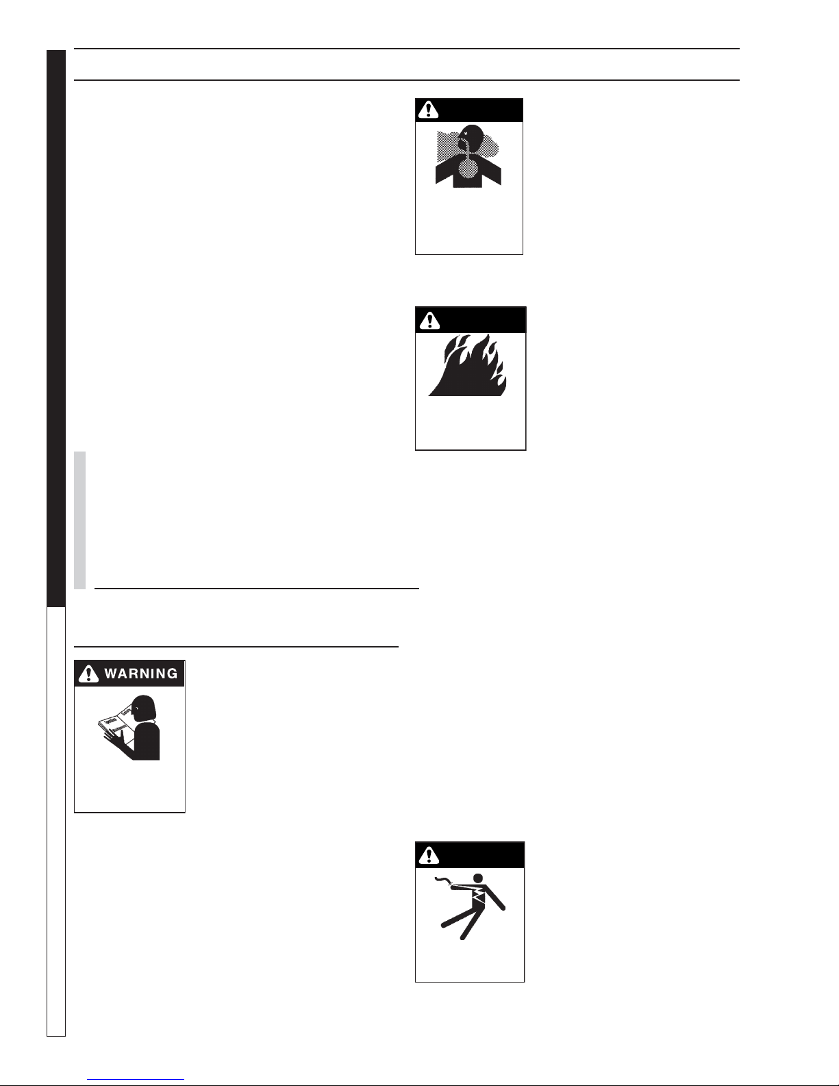
WARNING: To reduce the risk of
injury, read operating instructions carefully before using.
1. Read the owner's manual
thoroughly. Failure to follow
instructions could cause mal-
READ OPERATOR’S
MANUAL THOROUGHLY
PRIOR TO USE.
2. Know how to stop the machine and bleed pressure
quickly. Be thoroughly familiar with the controls.
3. Stay alert — watch what you are doing.
4. All installations must comply with local codes.
Contact your electrician, plumber, utility company
or the selling distributor for specifi c details.
function of the machine and
result in death, serious bodily
injury and/or property damage.
WARNING
WARNING: Risk of asphyxiation.
Use this product only in a well
ventilated area.
5. Avoid installing machines in
small areas or near exhaust
RISK OF
ASPHYXIATION. USE
THIS PRODUCT ONLY IN
A WELL
VENTILATED AREA.
fans. Exhaust contains poisonous carbon monoxide
gas; exposure may cause loss
of consciousness and may
lead to death. It also contains
chemicals known, in certain quantities, to cause
cancer, birth defects or other reproductive harm.
WARNING
WARNING: Risk of fi re. Do not
add fuel when the product is
operating.
WARNING: Risk of explosion —
do not spray fl ammable liquids.
RISK OF FIRE.
DO NOT ADD FUEL
WHEN OPERATING
MACHINE.
6. Do not place machine near
fl ammable objects as the engine is hot.
7. Allow engine to cool for 1-2 minutes before refueling. If any fuel is spilled, make sure the area is
dry before testing the spark plug or starting the
engine. (Fire and/or explosion may occur if this is
not done.)
Gasoline engines on mobile or portable equipment
shall be refueled:
a. outdoors;
b. with the engine on the equipment stopped;
c. with no source of ignition within 10 feet of
the dispensing point; and
d. with an allowance made for expansion of the
fuel should the equipment be exposed to a
higher ambient temperature.
In an overfi lling situation, additional precautions are
necessary to ensure that the situation is handled
in a safe manner.
WARNING: Risk of injury. Disconnect battery
ground terminal before servicing.
8. Transport/repair with fuel tank EMPTY or with fuel
shut-off valve OFF.
WARNING
WARNING: Keep wand, hose, and
water spray away from electric
wiring or fatal electric shock may
result.
9. Do not spray water on or near
electrical components.
KEEP WATER
SPRAY AWAY FROM
ELECTRICAL WIRING.
4
Shark BR 97-723 • REV. 3/07
Page 4
IMPORTANT SAFETY INFORMATION
PRESSURE WASHER
WARNING
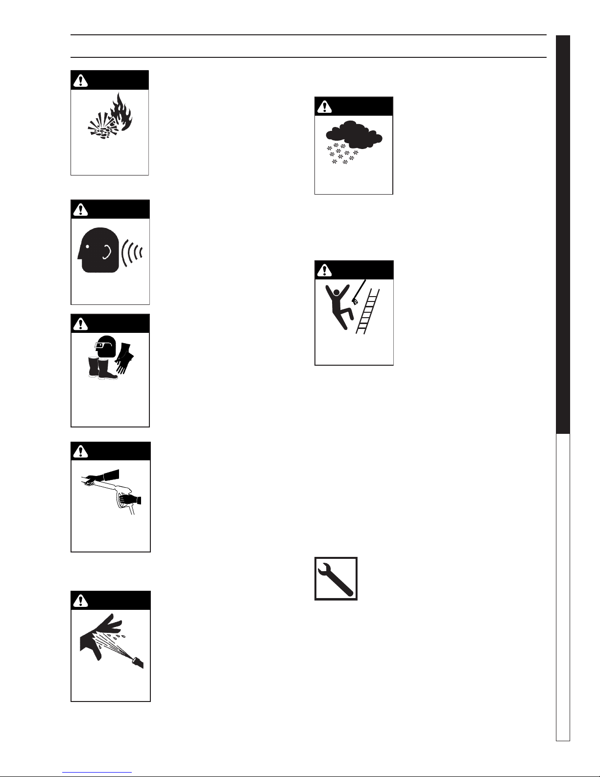
WARNING: Flammable liquids
can create fumes which can ignite, causing property damage
or severe injury.
WARNING: Risk of explosion
— Do not spray fl ammable liq-
RISK OF EXPLOSION:
DO NOT SPRAY
FLAMMABLE LIQUIDS.
uids.
10. Keep operating area clear of all persons.
WARNING
WARNING: This machine exceeds
85 db appropriate ear protection
must be worn.
EAR PROTECTION
MUST BE WORN
WARNING
WARNING: High pressure spray
can cause paint chips or other
particles to become airborne
and fl y at high speeds. To avoid
personal injury, eye, hand and
foot safety devices must be
USE PROTECTIVE
EYE WEAR
AND CLOTHING
WHEN OPERATING
THIS EQUIPMENT.
worn.
11. Eye, hand, and foot protection
must be worn when using this
equipment.
WARNING
WARNING: Grip cleaning wand
securely with both hands before
starting. Failure to do this could
result in injury from a whipping
wand.
TRIGGER GUN KICKS
BACK - HOLD WITH
BOTH HANDS
12. To reduce the risk of injury,
close supervision is necessary
when a machine is used near
children. Do not allow children
to operate the pressure washer. This machine
must be attended during operation.
WARNING
WARNING: High pressure devel-
oped by these machines will
cause personal injury or equipment damage. Keep clear of
nozzle. Use caution when operating. Do not direct discharge
RISK OF INJECTION
OR SEVERE INJURY
TO PERSONS. KEEP
CLEAR OF NOZZLE.
stream at people, or severe injury or death will result.
13. Never make adjustments on machine while in operation.
Shark BR 97-723 • REV. 3/07
14. Be certain all quick coupler fi ttings are secured
before using pressure washer.
WARNING
WARNING: Protect machine from
freezing.
15. To keep machine in best
operating conditions, it is
important you protect machine
from freezing. Failure to protect
PROTECT FROM
FREEZING
machine from freezing could
cause malfunction of the
machine and result in death,
serious bodily injury, and/or property damage. Follow storage instructions specifi ed in this manual.
16. The best insurance against an accident is precaution and knowledge of the machine.
WARNING
WARNING: Be extremely careful
when using a ladder, scaffolding
or any other relatively unstable
location. The cleaning area
should have adequate slopes
and drainage to reduce the pos-
RISK OF INJURY
FROM FALLS WHEN
USING LADDER.
sibility of a fall due to slippery
surfaces.
17. Do not overreach or stand on unstable support.
Keep good footing and balance at all times.
18. Do not operate this machine when fatigued or under
the infl uence of alcohol, prescription medications,
or drugs.
19. Inlet water must be clean fresh water and no hotter
then 90°F.
20. Manufacturer will not be liable for any changes
made to our standard machines or any components
not purchased from us.
21. Do not allow acids, caustic or abrasive fl uids to pass
through the pump.
22. Never run pump dry or leave spray gun closed
longer than 1-2 minutes.
Follow the maintenance instructions speci-
fi ed in the manual.
OPERATOR’S MAN U AL
5
Page 5
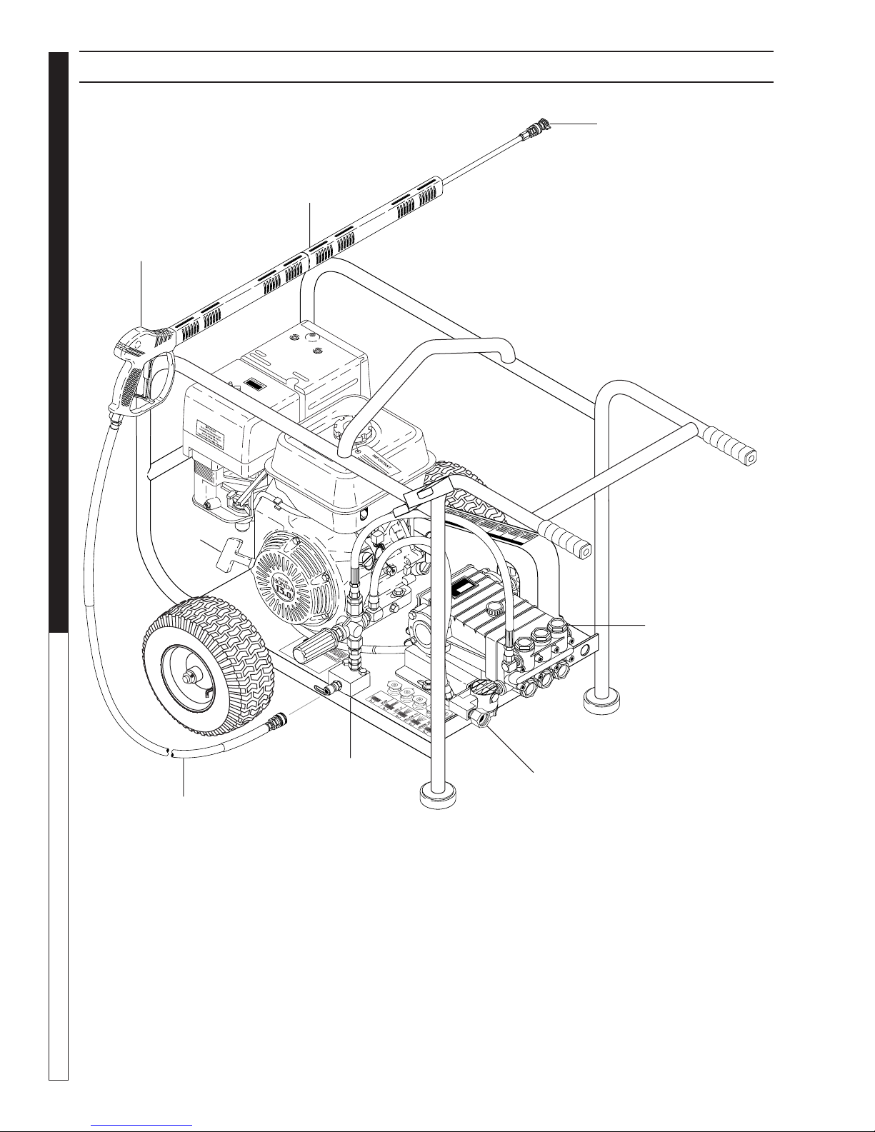
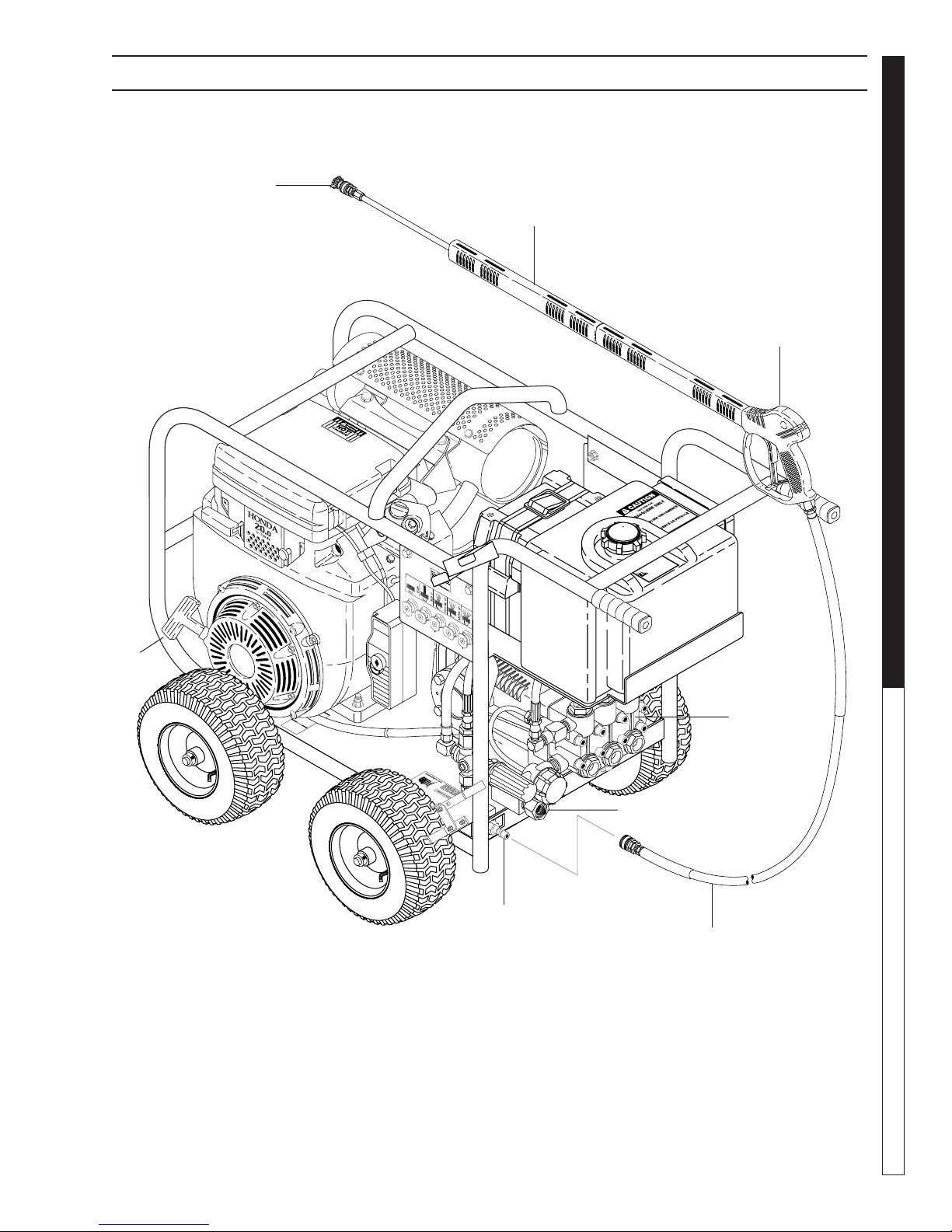
COMPONENT IDENTIFICATION — SMALL MODELS
Nozzle
Wand
PRESSURE WASHER
OPERATOR’S MANUAL
Spray Gun
Starter
Grip
Pump
High Pressure
Hose
Pump — Develops high pressure.
Starter Grip— Used for starting the engine man u al ly.
Spray Gun — Controls the application of water and
de ter gent onto cleaning surface with trigger device.
In cludes safe ty latch.
Detergent Injector — Allows you to siphon and mix
detergents (not shown).
6
High Pressure
Discharge
Shark BR 97-723 • REV. 3/07
Water Inlet
Wand — Must be connected to the spray gun.
High Pressure Hose — Connect one end to water
pump dis charge nipple and the other end to spray
gun.
Note: If trigger on spray gun is released for more
than 2 minutes, water will leak from valve. Warm
water will dis charge from pump protector onto fl oor.
This sys tem pre vents internal pump dam age.
Page 6
COMPONENT IDENTIFICATION — LARGE MODELS
Nozzle
Wand
Spray Gun
PRESSURE WASHER
OPERATOR’S MAN U AL
Starter
Grip
High Pressure
Discharge
Pump
Water Inlet
High Pressure
Hose
7
Shark BR 97-723 • REV. 3/07
Page 7
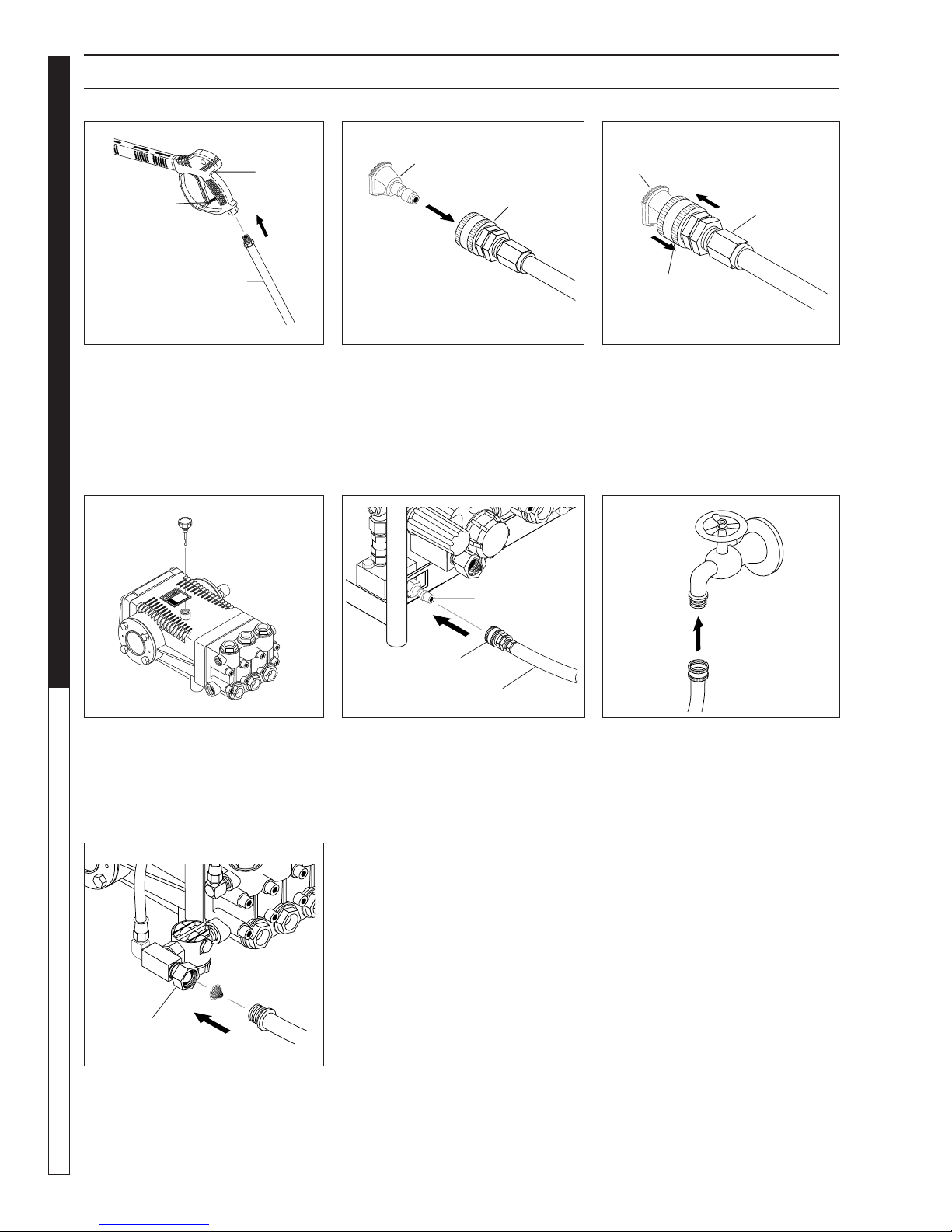
ASSEMBLY INSTRUCTIONS
Spray
Gun
Safety
Latch
PRESSURE WASHER
High Pressure
Hose
STEP 1: Attach the high pres sure
hose to the spray gun using tefl on
tape on hose threads.
OPERATOR’S MANUAL
Dipstick
Pressure
Nozzle
Wand
Coupler
STEP 2: Pull the spring-load ed col-
lar of the wand coupler back to in sert
your choice of pres sure noz zle.
Discharge
Nipple
Pressure
Nozzle
Wand
Coupler
Wand
Collar
STEP 3: Release the coupler col lar
and push the nozzle until the collar
clicks. Pull the nozzle to make sure
it is seat ed properly.
Cold
Water
Source
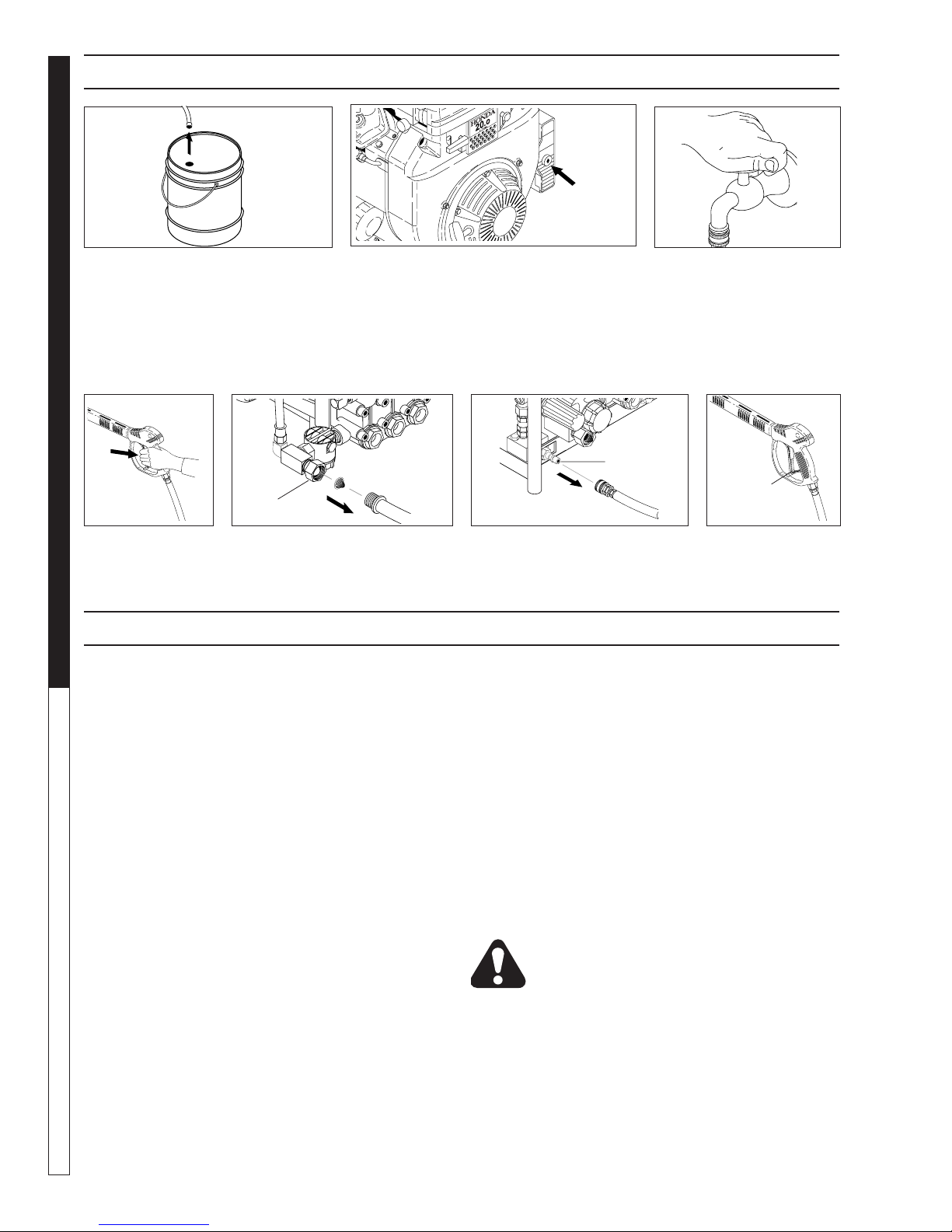
STEP 4: Remove shipping cap and
install oil dipstick. Check pump oil
level by using dipstick or observe
oil level in oil window (if equipped).
Use 30 wt. non detergent oil.
Pump
Water Inlet
STEP 7: Check inlet fi lters, remove
debris, then connect garden hose
to pump wa ter in let. CAU TION: Do
not run the pump with out wa ter or
pump dam age will result.
8
Garden
Hose
Coupler Collar
High Pressure Hose
STEP 5: Connect the high pres sure
hose to the pump discharge nipple.
Push coupler collar forward until
se cure.
Shark BR 97-723 • REV. 3/07
Garden
Hose
STEP 6: Connect garden hose to
the cold water source.
Page 8

OPERATING INSTRUCTIONS
Engine
Oil
Dipstick
PRESSURE WASHER
Gas
Tank
OPERATOR’S MAN U AL
STEP 1: Check engine oil level. Oil level should be level with the bottom
of the oil fi ller neck. Be sure the ma chine is level when checking the oil
level. (Refer to the en gine's op er at ing manual included with machine.) We
rec om mend that the oil be changed after the fi rst 5 hours of use, then once
every 50 hours. Note: Im prop er oil levels will cause low oil sensor to shut
off engine. IMPORTANT! Do not run engine with high or low oil levels
as this will cause engine damage.
Cold
Water
Source
Garden
Hose
STEP 3: Connect garden hose
to the cold water source and turn
wa ter on completely. Never use
hot wa ter.
STEP 4: Trigger the spray gun to
elim i nate trapped air then wait for a
steady fl ow of water to emerge from
the spray noz zle.
STEP 2: Fill gas tank with un lead ed
gasoline. Do not use leaded gas o line.
Fuel
Valve
STEP 5: Rotate the fuel shut-off valve to the "On"
po si tion. Slide the fuel valve lever to the "ON" position.
When the engine is not in use, leave the fuel valve in
the "OFF" position.
STEP 6: Pull the choke knob out to the "Choke" po si tion
(on a warm engine, when in the run po si tion, leave the
choke knob in). Push the choke knob to the "Closed"
po si tion. To restart a warm engine, leave the choke knob
in the "Open" position.
Shark BR 97-723 • REV. 3/07
Choke
Knob
9
Page 9
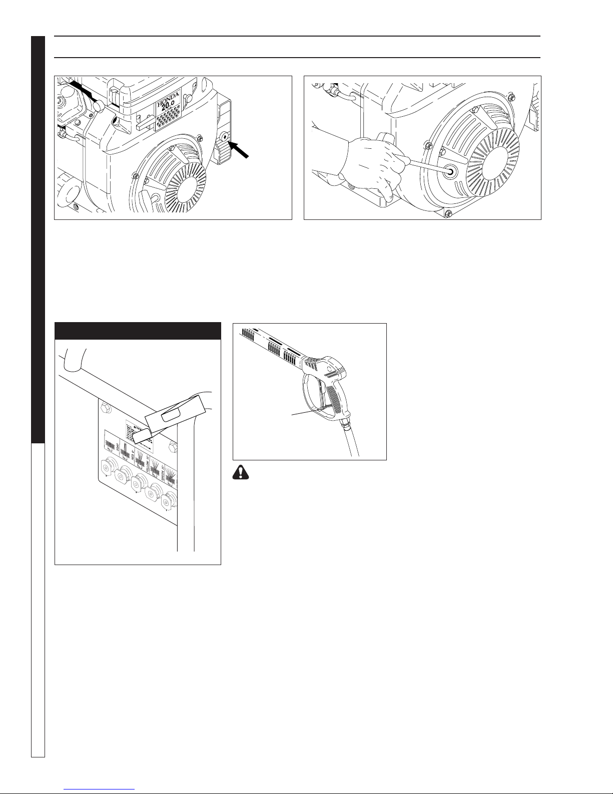
OPERATING INSTRUCTIONS (CON'T)
On-Off
PRESSURE WASHER
STEP 7: Turn the engine switch to "ON" position. STEP 8: Pull the starter grip. If the engine fails to start
OPERATOR’S MANUAL
NOZZLES
Switch
after 2 pulls, squeeze the trigger gun to release pres sure
and repeat step. Return start er gently. After the en gine
warms up enough to run smoothly, move choke to run
position and throt tle to fast position.
CAUTION: Small engines may kick back. Do not hold
pull starter grip tightly in hand.
The fi ve color-coded quick con nect
noz zles provide a wide array of spray
widths from 0° to 45° and are easily accessible when placed in the con ve nient
rubber nozzle holder, which is provided
on the front of the ma chine.
NOTE: For a more gentle rinse, se lect
the white 40° or green 25° noz zle. To
scour the surface, select the yellow 15°
or red 0° nozzle. To apply de ter gent
select the black noz zle.
Safety
Latch
WARNING! Never replace
noz zles without engaging the
safe ty latch on the spray gun
trig ger.
10
Shark BR 97-723 • REV. 3/07
Page 10
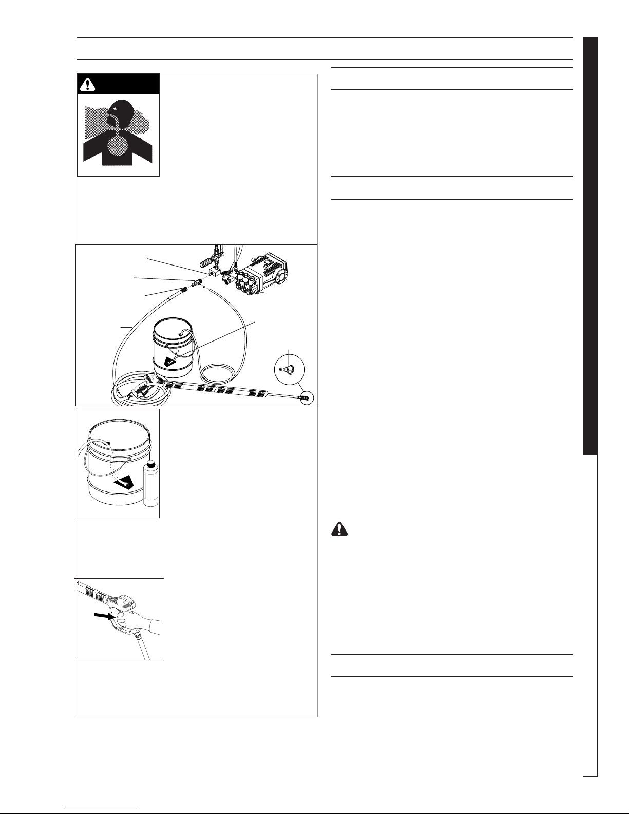
APPLYING DETERGENT AND GENERAL CLEANING TECHNIQUES
PRESSURE WASHER
WARNING
STEP 1: Connect detergent in jec tor to discharge nipple
on machine. Connect high pressure hose to in jec tor
with quick coupler. (Check to make sure locking cou pler
sleeves are in proper position before ap ply ing wa ter
pres sure).
Discharge
Nipple
Detergent
Injector
Quick Coupler
High
Pressure
Hose
WARNING: Some de ter gents
may be harm ful if in haled or
in gest ed, caus ing severe nau sea, fainting or poi son ing. The
harm ful el e ments may cause
prop er ty dam age or severe
injury.
Filter
Soap
Nozzle
THERMAL PUMP PROTECTION
If you run the engine on your pres sure wash er for 3-5
min utes with out pressing the trig ger on the spray gun,
cir cu lat ing water in the pump can reach high tem per a tures. When the water reach es this tem per a ture, the
pump pro tec tor engages and cools the pump by dis charg ing the warm water onto the ground. This ther mal
de vice pre vents internal dam age to the pump.
CLEANING TIPS
Pre-rinse clean ing surface with fresh water. Place de ter gent suc tion tube di rect ly into clean ing solution and
ap ply to sur face at low pressure (for best re sults, lim it
your work area to sec tions ap prox i mate ly 6 feet square
and al ways ap ply de ter gent from bottom to top). Allow
de ter gent to re main on sur face 1-3 min utes. Do not al low de ter gent to dry on sur face. If sur face appears to
be drying, sim ply wet down sur face with fresh water. If
need ed, use brush to re move stub born dirt. Rinse at
high pres sure from top to bottom in an even sweep ing
mo tion keep ing the spray nozzle ap prox i mate ly 1 foot
from clean ing sur face. Use over lap ping strokes as you
clean and rinse any sur face. For best surface clean ing
action spray at a slight an gle.
OPERATOR’S MAN U AL
STEP 2: Use detergent de signed
spe cifi cal ly for pres sure washers.
House hold de ter gents could dam age the pump. Pre pare detergent
so lu tion as required by the man u fac tur er. Fill a container with pres sure washer de ter gent. Place the
fi lter end of detergent suction hose
into the de ter gent container.
STEP 3: With safety latch on spray gun engaged,
se cure black soap noz zle into quick cou pler.
NOTE: De ter gent can not be ap plied using red, yellow,
green or white noz zles.
STEP 4: With the engine run ning,
pull trig ger to op er ate ma chine.
Liq uid detergent is drawn into the
ma chine and mixed with water.
Apply de ter gent to work area.
Do not al low de ter gent to dry on
sur face.
IMPORTANT: You must fl ush the detergent in jec tion
sys tem after each use by plac ing the suction hose
into a buck et of clean wa ter, then run the pres sure
wash er in low pres sure for 1-2 minutes.
Recommendations:
• Before cleaning any surface, an inconspicuous
area should be cleaned to test spray pattern and
dis tance for maximum cleaning results.
• If painted surfaces are peeling or chipping, use
ex treme caution as pressure washer may re move
the loose paint from the surface.
• Keep the spray nozzle a safe distance from the
sur face you plan to clean. High pressure wash a
small area, then check the surface for damage. If no
dam age is found, continue to pressure wash ing.
CAUTION - Never use:
• Bleach, chlorine products and other corrosive
chem i cals
• Liquids containing solvents (i.e., paint thinners,
gas o line, oils)
• Tri-sodium phosphate products
• Ammonia products
• Acid-based products
These chemicals will harm the machine and will dam age the surface
being cleaned.
RINSING
It will take a few sec onds for the de ter gent to clear.
Apply safe ty latch to spray gun. Re move black soap
noz zle from the quick cou pler. Select and in stall the
de sired high pres sure noz zle. NOTE: You can also stop
de ter gent from fl ow ing by sim ply re mov ing de ter gent
si phon hose from bottle.
11
Shark BR 97-723 • REV. 3/07
Page 11
SHUTTING
DOWN
AND CLEAN-UP
On-Off
Switch
STEP 1: Remove detergent suc tion
PRESSURE WASHER
tube from container and insert into
one gallon of fresh water. Slide noz zle
for ward for low pressure or to con nect
black detergent nozzle. Pull trig ger
on spray gun and si phon water for
one minute.
OPERATOR’S MANUAL
Water
Inlet
STEP 4: Press trig-
ger to re lease wa ter
pres sure.
CAUTION: Al ways store your pressure washer in a
lo ca tion where the temperature will not fall be low
32°F (0°C). The pump in this machine is sus cep ti ble
to permanent dam age if fro zen. FREEZE DAM AGE
IS NOT COV ERED BY WARRANTY.
1. Stop the pressure washer, squeeze spray gun trig ger to release pressure.
2.
Detach water supply hose and high pressure hose.
3. Turn on the machine for a few seconds, until re main ing water exits. Turn engine off im me di ate ly.
4. Drain the gas and oil from the engine.
5.
Do not allow high pressure hose to become
kinked.
6. Store the machine and accessories in a room which
does not reach freezing temperatures.
CAUTION: Fail ure to follow the above di rec tions will
result in dam age to your pres sure washer.
When the pres sure washer is not being operated or is
be ing stored for more than one month, follow these
in struc tions:
1. Replenish engine oil to up per level.
2. Drain gas o line from fuel tank, fuel line, fuel valve
and carburetor.
3. Pour about one teaspoon of engine oil through
12
the spark plug hole, pull the starter grip several
STEP 5: Disconnect the garden
hose from the water inlet on the
machine.
STEP 2: Turn engine switch to "OFF"
position.
Shark BR 97-723 • REV. 3/07
STEP 6: Disconnect the high
pres sure hose from the discharge nipple.
STORAGE
times and re place the plug. Then pull the starter
grip slow ly until you feel increased pressure which
indicates the pis ton is on its compression stroke and
leave it in that position. This closes both the intake
and ex haust valves to prevent rusting of cylinder.
4. Cover the pressure washer and store in a clean, dry
place that is well ventilated away from open fl ame
or sparks. NOTE: The use of a fuel additive, such
as STA-BIL®, or an equivalent, will minimize the
for mu la tion of fuel deposits during storage. Such
ad di tives may be added to the gasoline in the fuel
tank of the engine, or to the gasoline in a storage
con tain er.
After Extended Storage
Engine Maintenance
During the winter months, rare atmospheric conditions
may develop which will cause an icing con di tion in the
car bu re tor. If this de vel ops, the engine may run rough,
lose power and may stall. This temporary condition can
be overcome by defl ecting some of the hot air from the
en gine over the carburetor area. NOTE: Refer to the
en gine man u fac tur er's manual for service and main te nance of the engine.
STEP 3: Turn off water
sup ply.
Discharge
Nipple
Safety
Latch
STEP 7: En gage
the spray gun safe ty
lock.
CAUTION: Prior to restarting, thaw out any
pos si ble ice from pressure washer hos es,
spray gun or wand.
Page 12

TROUBLESHOOTING
PROBLEM POSSIBLE CAUSE SOLUTION
LOW OPERATING
PRESSURE
FLUCTUATING
PRESSURE
PRESSURE LOW
AFTER PERIOD OF
NORMAL USE
ENGINE WILL NOT
START OR STOPS
WHILE OPERATING
ENGINE IS
OVERLOADED
WATER OR OIL
LEAKING FROM
BOTTOM OF PUMP
PRESENCE OF WATER
IN PUMP OIL
Insuffi cient water supply. Closed
faucet. Inlet hose kinked
Clogged inlet hose strainer Check plumbing system for leaks. Retape
Faulty or misadjusted unloader
valve
Worn packing in pump Call technical support.
Machine has been stored in freezing temperatures.
Slow engine RPM Call technical support.
Worn or dirty pump valves Call technical support.
Nozzle is obstructed Use nozzle wire in accessory kit.
Pump sucking air, inlet hose leaking
Nozzle worn Replace nozzle.
Unloader valve worn Replace unloader valve.
Low oil shutdown Fill engine with oil.
Water in gasoline Drain gas tank; fi ll with clean fuel.
Out of gas Fill fuel tank.
Nozzle partially blocked Clean nozzle.
Excessive pressure from high
engine RPM
A small amount of leaking is
normal
Water sprayed at machine Change oil. Direct spray away from ma-
High humidity in air Check and change oil twice as often.
Piston packing worn. Oil seal
worn
Use larger garden hose; clean inlet water
screen. Open faucet.
leaks with tefl on tape.
Adjust unloader for proper pressure. Install
repair kit when needed. Call technical support.
Thaw out machine completely, including
hose, spray gun and wand.
Check all pump lines and connections.
Adjust engine throttle to lower RPM.
If excessive leaking occurs, call technical
support.
chine.
Call technical support.
PRESSURE WASHER Troubleshooting Guide
13
Shark BR 97-723 • REV. 3/07
Page 13

TROUBLESHOOTING
PROBLEM POSSIBLE CAUSE SOLUTION
ENGINE OPERATES
FOR 15 MIN. THEN
STOPS
ENGINE LACKS POWER
ENGINE FALTERS
PRESSURE WASHER
WATER DRIPPING
FROM UNDER PUMP
OIL DRIPPING
WATER LEAKING FROM
PUMP PROTECTOR
OPERATOR’S MANUAL
NO DETERGENT
GARDEN HOSE
CONNECTION LEAKS
SPRAY WAND LEAKS
PUMP IS NOISY
Not enough gas or engine oil Fill tank with gas. Check oil level.
Vapor lock developed by heat of
day
Obstruction in fuel fi lter Clean or replace fuel fi lter.
Dirty air fi lter Replace air fi lter.
Choke is opened too soon Move choke to halfway position until en-
Piston packing worn Call technical support.
O-Ring plunger retainer worn Call technical support.
Cracked piston Call technical support.
Oil seal worn or damaged Call technical support.
Spray gun closed with machine
running 5 minutes or longer
Excess water supply pressure Place a pressure regulator at end of 50’
Detergent suction tube not properly connected to machine
Detergent is too thick Dilute detergent. For best results, use
Detergent fi lter valve is at lowest
setting
Filter on detergent suction tube is
clogged
Damaged or clogged detergent
suction tube
A high pressure nozzle is attached.
Discharge nozzle is obstructed Blow out or remove debris with fi ne needle.
Loose fi ttings Tighten fi ttings.
Missing/worn rubber washer Insert new washer.
Spray wand not properly attached Slide the spray wand into the gun. Turn the
Broken o-ring Call customer service and order an o-ring.
Pump is sucking air Check that hoses and fi ttings are air tight.
Keep gas tank full to avoid vapor locking.
gine runs smoothly.
Open spray gun or turn off machine.
garden hose.
Check connection.
Rhino detergent.
Set detergent fi lter valve to a higher setting.
Run warm water through fi lter to remove
debris.
Remove obstruction or replace detergent
suction tube.
Replace with black detergent nozzle.
wand collar clockwise onto the spray gun
threads until tight.
Turn off machine and purge pump by
squeezing trigger gun until a steady fl ow of
water emerges through nozzle.
14
Shark BR 97-723 • REV. 3/07
Page 14

PREVENTATIVE MAINTENANCE
This pressure washer was produced with the best avail able ma te ri als and quality craftsmanship. However, you
as the own er have certain re spon si bil i ties for the correct care of the equip ment. At ten tion to reg u lar pre ven ta tive
main te nance pro ce dures will as sist in preserving the per for mance of your equipment. Contact your dealer for
main te nance. Regular pre ven ta tive main te nance will add many hours to the life of your pres sure washer. Per form
main te nance more often under severe conditions.
PRESSURE WASHER
Pump Oil Inspect
Change
Replace high pressure nozzle
Replace quick connects
Clean water screen/fi lter
Replace HP hose
Grease motor
Daily inspect the oil level
After fi rst 50 hours, then every 500 hours or
annually
Every 6 months
Annually
Weekly
Annually if there is any sign of wear
Every 10,000 hours
OIL CHANGE RECORD
Check pump oil and engine oil level before fi rst use of your new pressure washer.
Date Oil Changes
Month/Day/Year
Estimated Operating
Hours Since Last Oil
Change
Date Oil Changes
Month/Day/Year
OPERATOR’S MAN U AL
Estimated Operating
Hours Since Last Oil
Change
15
Shark BR 97-723 • REV. 3/07
Page 15

EXPLODED VIEW - LARGE
PRESSURE WASHER
OPERATOR’S MANUAL
2
31
27
23
8, 9
50
404027, 404029
79
16
Models
22
18
43
45
59
88
40
45
20
18
39
62
54
56
1
4
57
12
3
60
55
5
73
57
59
63
44
57
37
34
36
35
38
91
89
90
28
26
16
84
78
33
9
8
50
22
18
65
77
61
19
15
All Models
Except
32
21
4040
14
23
73
76
52
75
13
53
Models
404027,
404029
7
48
74
29
48
74
49
49
42
48
82
48
74
59
30
74
29
11
86
87
59
83
74
60
74
48
85
53
59
47
48
41
71
25
59, 60, 61
60
93
92
24
6
94
49
48
74
70
72
58
67
66
81
59
80
64
68
95
60
7269
58
70
59
60
17
46
51
51
16
Shark BR 97-723 • REV. 3/07
Page 16

EXPLODED VIEW PARTS LIST- LARGE
PRESSURE WASHER
ITEM PART NO. DESCRIPTION QTY
1 10-02011 Label, This Tank For Gas Only
(405039E, 455037E, 455039E,
455034E) 1
2 10-02025A Label, “Hot/Caliente” w/Arrows 1
3 10-02029 Label, Danger Cool Engine
(455037E, 405039E, 455039E
455034E) 1
4 11-01011 Label, Warning Pictoral(Small) 1
5 11-013 ▲ Label, Logo, Belt Guard
(BR) 1
10-03014 ▲ Label, Logo, Belt Guard
(MP) 1
11-3227 ▲ Label, Logo, Belt Guard
(BD) 1
6 11-0316 Label, Instructions 1
7 10-03008 Label, Nozzle Identifi cation 1
8 2-0051 Nipple, 1/2” JIC, 3/8” Pipe 1
9 2-0079 Swivel, 1/2" JIC Fem,
3/8" Male 1
10 2-010061 Bushing, Rubber, Nitrile (405039E,
455039E, 455034E, 455037E) 1
11 2-0103 Grommet, Rubber, Nozzle
Holder 5
12 2-011507 Tank, Encore 5 Gal. Tank
(405039E, 455039E, 455034E
455037E) 1
13 2-01167 Cap, Fuel Tank, Plastic (405039E,
455039E, 455034E, 455037E) 1
14 2-0117 Battery, Box (405039E, 455039E,
455034E, 455037E) 1
15 2-011700 Plate, Battery Box, Small, Polypro
(405039E, 455039E, 455034E,
455037E) 1
16 2-0051 Nipple 1/2" JIC x 3/8" Male
(404027, 404029) 1
2-00510 Nipple, 1/2" JIC x 3/8" Fem
(405039E, 455034E, 455037E,
455039E) 1
17 2-0155 Fastener, Ratchet, Black Nylon 2
18 2-1062 Elbow, 1/2" JIC x 1/2", 90°
(405039E, 455034E, 455037E
455039E) 2
(404027, 404029) 1
2-1060 Elbow, 1/2” JIC x 3/8”, 90°
(404027, 404029) 1
19 2-10942 Swivel, 1/2"MP x 3/4" GHF
w/Strainer 1
20 2-1105 Swivel, 1/2" JIC Fem, Push-On 2
21 2-1923 Strainer, 1/2" PA, Inline Plastic 1
Shark BR 97-723 • REV. 3/07
ITEM PART NO. DESCRIPTION QTY
22 2-20022 Nipple, 3/8" Fem, 11,000 PSI”
(405039E, 455039E, 455034E,
455037E) 1
2-2007 Nipple, 3/8" x 3/8" NPT ST Male
(404027, 404029) 1
23 2-30082 Pump Protector, 1/2" PTP
(405039E, 455039E, 455034E,
455037E) 1
2-300816 Pump Protector, 3/8" (404027,
404029) 1
24 6-05137 Cable Tie Mount, Black (405039E,
455034E, 455037E) 2
25 2-9016 Clamp, Round, 0.56 I.D. (405039E,
455039E, 455034E, 455037E) 1
26 4-02047914 Hose, 3/8" x 14", 2 Wire,
Pressure Loop (405039E, 455034E
455037E, 455039E) 1
4-02047714 Hose, 3/8" x 1/4", 2 Wire Pressure
(404027, 404029) 1
27 4-02100000 Hose, 1/4", Push-On, Fuel Line
(405039E, 455039E, 455034E,
455037E)
28 4-02110000 Hose, 1/2", Push-On 15"
29 4-0307 Wheel & Tire Cmpl, 6" 4
30 4-12803500 Nozzle, SACQMEG, 0003.5, Red
(405039E) 1
4-12803515 Nozzle, SAQCMEG 1503.5, Yellow
(405039E) 1
4-12803525 Nozzle, SAQCMEG, 2503.5,
Green (405039E) 1
4-12803540 Nozzle, SAQCMEG 4003.5, White
(405039E) 1
4-12804000 Nozzle, SAQCMEG 0004, Red
(404029, 404027,455039E,
455034E, 455037E) 1
4-12804015 Nozzle, SAQCMEG 1504, Yellow
(404029, 404027,455039E,
455034E, 455037E) 1
4-12804025 Nozzle, SAQCMEG 2504, Green
(404029, 404027,455039E,
455034E, 455037E) 1
4-12804040 Nozzle, SAQCMEG 4004, White
(404029, 404027,455039E,
455034E, 455037E) 1
4-16540 Nozzle COMPL, QCEM-6540,
Brass (404029, 455039E, 405039E,
455034E, 455037E) 1
31 Engine, See Specifi cations Pages
32 Pump, See Specifi cations Pages
33 Unloader, See Specifi cations Pages
34 Engine Pulley, See Specifi cations Pages
35 Pump Pulley, See Specifi cations Pages
36 Pump Bushing, See Specifi cations Pages
37 Engine Bushing, See Specifi cations Pages
57"
OPERATOR’S MAN U AL
17
Page 17

EXPLODED VIEW PARTS LIST- LARGE
ITEM PART NO. DESCRIPTION QTY
38 Belts, See Specifi cations Pages
39 6-05109 Cable, Battery, 32" Red, 4 Gauge
(405039E, 455039E, 455034E
455037E) 1
40 6-051092 Cable, Battery, 36" Black, 4 Gauge
(405039E, 455039E, 455034E,
455037E) 1
41 2-30057 Valve, Shut-Off, 1/4 Turn (405039E,
PRESSURE WASHER
455039E, 455034E, 455037E) 1
42 90-1007 Bolt, 5/16" x 1", NC HH (405039E,
455039E, 455034E, 455037E) 4
(404027,404029) 2
43 90-1010 Bolt, 5/16" x 1-3/4", NC HH
(404027, 404029) 4
90-1020 Bolt, 3/8" x 2", NC, HH (405039E,
455034E, 455037E, 455039E) 4
44 90-10343 Bolt, 10mm x 20mm, HH 4
OPERATOR’S MANUAL
45 90-1020 Bolt, 3/8" x 2" NC, HH 2
46 90-102746 Bolt, 1/2" x 5" NC HH Tap (404027,
404029, 405039E, 455039E,
455034E, 455037E) 1
47 90-18012 Screw, 1/4" x 5/8", Phil PH MS
(405039E, 455034E, 455037E,
455039E) 4
48 90-20041 Collar, 5/8" Bore Shaft 8
49 90-40181 Washer , Nylon Spacer, 0.656 x
1.25 x 0.65 THK 4
50 95-07101216/B Block, Unloader, 3/8" x 3/8"
Brass 1
51 95-07393125 Axle, 5/8" x 31.25" 2
52 95-07104028 Guard, Belt, Rear Steel 1
53 95-07162047 Assy, Weld, Battery Brkt, CW
Cage, Red (405039E, 455039E,
455037E) 1
95-07162048 Assy, Weld, Battery Brkt, CW
Cage, Black (455034E) 1
95-07162081 Holder, Nozzle (404027
404029) 1
54 95-07162054 Assy, Weld, Cage, CW Red
(BD, BR) 1
95-07162055 Assy. Weld, Cage, CW Black
(MP) 1
55 95-07162045 Guard, Belt, Front, CW Cage,
Black 1
56 95-07162071 Assy, Weld, Slider, CW Cage,
Red (404029, 405039E, 455037E,
455039E, 404027) 1
95-07162072 Assy, Weld, Slider, CW Cage,
Black (455034E) 1
57 90-1995 Screw, 1/4" x 1/2" BH SOC CS 7
58 90-2000 Nut, 1/4" ESNA, NC 4
ITEM PART NO. DESCRIPTION QTY
59 90-4001 Washer, 5/16" FLAT, SAE (405039E,
455034E, 455037E, 455039E) 20
(404027,404029) 16
90-4002 Washer, 3/8" (404027, 404029) 2
(405039E, 455034E, 455037E,
455039E) 10
60 90-2001 Nut, 5/16" ESNA, NC (404027,
404029) 10
(405039E, 455034E, 455037E,
455039E) 12
90-2002 Nut, 3/8" ESNA (404027,
404029) 2
(405039E, 455034E, 455037E,
455039E) 6
61 90-100543 Screw, 5/16"-18 x 3/4" M PH
TRH (405039E, 455034E, 455037E,
455039E) 4
62 2-1046 Plug, 1/4" Countersunk (405039E,
455034E,455037E, 455039E) 1
63 90-400910 Washer, 7/16" Lock-Split Ring 4
64 2-01103 Grip, 1" Square Handle 2
65 2-10323 Tee, 1/2", Branch Male 1
66 95-07104828 Bracket, Brake Pad, Red
(BD, BR) 1
95-07164828 Bracket, Brake Pad, Black (MP) 1
67 95-07164829 Linkage, Brake, Black (MP) 1
95-07104829 Linkage, Brake, Red (BD, BR) 1
68 90-3096 Washer, 1/2" Flat 1
69 95-07162065 Handle, Break, CW Cage,
Red (BD, BR) 1
95-07162066 Handle, Break, CW Cage,
Black (MP) 1
70 90-100472 Bolt, Carriage, Zinc, 1/4"-20 x 1.0
PLT 4
71 2-9040 Clamp, Hose, .46-.54 ST
(405039E, 455039E, 455034E,
455037E) 2
72 90-4000 Washer, 1/4" Flat, SAE 12
73 90-40001 Washer, 1/4" FLAT, SAE, Black,
Zinc 5
74 90-4005 Washer, 5/8" Flat 8
75 1-100534 Valve, Safety Relief, 6000PSI
(405039E, 455039E, 455034E,
455037E) 1
76 2-0031 Elbow, 3/8" Street (405039E,
455039E, 455034E, 455037E) 1
77 2-0006 Nipple, 3/8" Hex Steel (405039E,
455037E, 455039E, 455034E) 1
78 2-0053 Elbow, 1/2" JIC, 3/8", 90° 1
18
Shark BR 97-723 • REV. 3/07
Page 18

EXPLODED VIEW PARTS LIST- LARGE
ITEM PART NO. DESCRIPTION QTY
79 77-VHRM4 Muffl er, Honda, GX620/670 Right
(405039E, 455037E, 455039E,
455034E) 1
76-807964 ▲ Muffl er, Exhaust, Briggs 16HP
(404029, 404027) 1
95-07101149 ▲ Guard, Muffl er, Briggs 16HP
(404029, 404027) 1
95-071011491▲ Brace, Muffl er Guard (404029,
404027) 2
76-495518 ▲ Muffl er, Defl ector, Vanguard
(404027, 404029) 1
79-11465813800
▲ Defl ector, Exhaust, Honda
(405039E, 455037E, 455039E,
455034E) 1
80 10-9999 Clear Lexan 1
81 10-08017 Label, Intended For Outdoor
Use 1
82 9.800-049.0 Label, Manuf. Cleaning Solution 1
83 2-00471 Plug, 1/8" Square Head, Black
(405039E, 455037E,455039E,
455034E) 1
84 2-1100 Adaptor, 1/2 x 1/2 (455037E,
404027, 404029, 455039E,
455034E) 1
85 90-19980 Screw, 1/4" x 1" (405039E,
455034E, 455037E, 455039E) 2
86 90-40001 Washer, 1/4" Flat, SAE, Black
(405039E, 455034E, 455037E,
455039E) 2
87 90-2000 Nut, 1/4" ESNA (405039E,
455034E, 455037E, 455039E) 2
88 4-011184 Chemical Injector Assy, 3-5 GPM,
.83 (404027, 404029) 1
4-011186 Downstream Injector Assy
(405039E, 455039E, 455034E,
455037E) 1
89 4-0211000 Hose, 1/2" Push-On 14"
90 2-1050 Plug, 1/2" JIC 1
91 2-1060 Elbow, 1/2" JIC x 3/8" 1
92 2-9013 Clamp 1/2" 1
93 90-1999 Screw, 10/32" 1
94 90-20047 Nut 10/32" 1
95 90-4000 Washer 1
▲ Not Shown
PRESSURE WASHER
OPERATOR’S MAN U AL
19
Shark BR 97-723 • REV. 3/07
Page 19

EXPLODED VIEW - SMALL
PRESSURE WASHER
OPERATOR’S MANUAL
51
5
7
15
55
48
40
41
59
56
41
59
30
55
56
34
22
35
33
57
1
29
2
37
45
9
37
24
60
9
23
18
25
21
50
32
11
26
31
10
36
21
19
17
20
43
27
43
49
53
16
4
3
28
12
6
58
46
54
45
42
8
13
47
38
52
14
44
49
43
43
27
39
20
Shark BR 97-723 • REV. 3/07
Page 20

EXPLODED VIEW PARTS LIST- SMALL
PRESSURE WASHER
ITEM PART NO. DESCRIPTION QTY
1 10-02025A Label, "Hot/Caliente" w/Arrows
Warning 1
2 10-02029 Label, Danger Cool Engine 1
3 10-08017 Label, Intended For Outdoor Use 1
4 10-9999 Label, Clear Lexan,
2-1/4" x 4-1/2" 1
5 11-01011 Label, Warning, Pictoral, Small 1
6 11-0316 Label, Instructions 1
7 10-0623 Label, Belt Guard, MP (373534) 1
11-32289 La bel, Belt Guard, BD (373539) 1
11-3229 La bel, Belt Guard, BR (442537,
353237,373537,304037) 1
8 10-03008 Label, Nozzle Identifi cation 1
9 2-0051 Nipple, 1/2" JIC, 3/8" Pipe 2
10 2-0053 Elbow, 1/2" JIC, 3/8", 90° 1
11 2-0079 Swivel, 1/2" JIC Fem, 3/8" Male 1
12 2-0103 Grommet, Rubber, Nozzle
Holder 5
13 2-01041 Pad, Soft Rubber, 50 Duro 2
14 2-01103 Grip, 1" Square, Handle 2
15 2-0117200 Belt Guard, CW 1
16 2-0155 Fastener, Ratchet, Black Nylon 2
17 2-10323 Elbow, 1/2" Street, Brass 1
18 2-1060 Elbow, 1/2" JIC x 3/8", 90° 1
19 2-1062 Elbow, 1/2" JIC x 1/2", 90° 1
20 2-10942 Swivel, 1/2" MP x 3/4" GHF
w/Strainer 1
21 2-1105 Swivel, 1/2" JIC Fem, Push-On 2
22 2-1923 Strainer, 1/2" PA, Inline Plastic 1
23 2-2007 Nipple, 3/8" x 3/8" NPT ST
Male 1
24 2-300816 Pump Protector, 3/8" PTP 1
25 4-02047720 Hose, 3/8" x 20", 2 Wire,
Pressure Loop 1
26 4-02110000 Hose, 1/2", Push-On 15"
27 4-0307 Wheel & Tire Assy, 6" Steel Rim
w/Tube 2
28 4-12804000 Nozzle, SAQCMEG 0004, Red
(373539,353237,373534,
373537) 1
4-12804015 Noz zle, SAQCMEG 1504, Yellow
(373539,353237,373534,
373537) 1
4-12804025 Nozzle, SAQCMEG 2504, Green
(373539,353237,373534,
373537) 1
4-12804040 Nozzle, SAQCMEG 4004, White
(373539,353237,373534,
373537) 1
Shark BR 97-723 • REV. 3/07
ITEM PART NO. DESCRIPTION QTY
28 4-12805500 Nozzle, SAQCMEG 0005.5, Red
(442537) 1
4-12805515 Nozzle, SAQCMEG 1505.5, Yellow
(442537) 1
4-12805525 Nozzle, SAQCMEG 2505.5, Green
(442537) 1
4-12805540 Nozzle, SAQCMEG 4005.5, White
(442537) 1
4-12803000 Nozzle, SAQCMEG .0003, Red
(304037) 1
4-12803015 Nozzle, SAQCMEG 1503, Yellow
(304037) 1
4-12803025 Nozzle, SAQCMEG 2503, Green
(304037) 1
4-12803040 Nozzle, SAQCMEG 2504, White
(304037 1
4-16540 Nozzle, COMPL, QCEM-6540,
Brass (373539) 1
29 Engine, See Specifi cations Pages 24, 25
30 Pump, See Specifi cations Pages 24, 25
31 Unloader, See Specifi cations Pages 24, 25
32 Engine Pulley, See Specifi cations Pages 24, 25
33 Pump Pulley, See Specifi cations Pages 24, 25
34 Engine Bushing, See Specifi cations Pages 24, 25
35 Pump Bushing, See Specifi cations Pages 24, 25
36 Belt, See Specifi cations Pages 24, 25
37 90-1020 Bolt, 3/8" x 2" NCHH 6
38 90-1018 Bolt, 3/8" x 1-1/2", NC HH 2
39 90-102751 Bolt, 1/2" x 3-1/2", NC HH 1
40 90-10343 Bolt, 10mm x 20mm, HH 4
41 90-19710 Screw, 1/4" x 3/4" HH NC, Whiz 3
42 90-2002 Nut, 3/8" ESNA, NC 4
43 90-20041 Collar, 5/8" Bore Shaft 3010 4
44 90-3096 Washer, 1/2" Flat 1
45 90-4002 Washer, 3/8" Flat, SAE 8
46 90-4002 Washer, 3/8" SAE, Flat 2
47 90-40125 Washer, 3/8" x 1" 2
48 90-400910 Washer, 7/16", Lock Split Ring 4
49 90-40181 Washer, Nylon Spacer, 0.656" x
1.25" x 0.65" Thick 2
50
Brass 1
51 95-07104001 Slider, Pump/Belt Guard Mount,
Red (BD, BR) 1
95-07104033 Slider, Pump/Belt Guard Mount,
Black (MP) 1
52 95-07104723 Axle, 5/8" x 27.80 L 1
53 95-07162004 Assy, Weld, CW Cage, Small
Red (BD, BR) 1
95-07162005 Assy, Weld, CW Cage, Small
Black (MP) 1
95-07101216/B
Block, Unloader, 3/8" x 3/8"
OPERATOR’S MAN U AL
21
Page 21

EXPLODED VIEW PARTS LIST- SMALL
ITEM PART NO. DESCRIPTION QTY
54 90-2002 Nut, 3/8" ESNA, NC 2
55 90-2001 Nut, 5/16" ESNA 4
56 90-4001 Washer, 5/16" Flat 7
57 2-1100 Adapter, 1/2 x 1/2 (304037, 373534,
353237, 442537, 373539,
373537) 1
58 9.800-049.0 Label, Manufacturer's Cleaning
PRESSURE WASHER
Solution 1
59 90-4000 Washer, 1/4" Flat 3
60 4-011184 Chemical Injector Assy, 3-5 GPM,
.83 1
OPERATOR’S MANUAL
22
Shark BR 97-723 • REV. 3/07
Page 22

HOSE & SPRAY GUN ASSEMBLY
1, 2
PRESSURE WASHER
9
4
8
7
3
6
57
HOSE & SPRAY GUN ASSEMBLY PARTS LIST
ITEM PART NO. DESCRIPTION QTY
1 4-0110331 Wand, Side Grip w/Couplers 47.5"
(373539, 404029) 1
4-012192 Spray Gun w/Wand (5000 PSI),
w/Coupler (405039E, 455039E,
455034E, 455037E) 1
4-011143A Wand, SS V.P. Wand, (AL 344)
w/Coupler, w/Soap Nozzle
(373534) 1
4-0111341A Wand, V.P. w/Coupler & Nozzle,
X-Series (353237, 373537, 404027,
442537) 1
2 4-012402 Spray Gun Assy, w/Nipple (373539,
404029) 1
4-01246 Spray Gun, Shut-Off, AP 1000
(442537, 353237, 373537, 404027,
304037) 1
4-01212 Gun, Shut-Off (373534) 1
3 8.739-054.0 Hose, 3/8" x 50', 2-Wire,
TUFF-Skin (405039) 1
8.739-072.0 Hose, 3/8" x 50', 2-Wire,
TUFF-Flex (455034) 1
8.739-078.0 Hose, 3/8" x 50', 2-Wire,
TUFF-Flex (455037) 1
8.739-183.0 Hose, 3/8" x 50', 2-Wire,
TUFF-Flex (404029) 1
8.739-213.0 Hose, 3/8" x 50', 2-Wire,
TUFF-Flex (373534) 1
8.739-148.0 Hose, 3/8" x 50', 1-Wire, Blue,
TUFF-Flex (442537, 353237) 1
8.739-229.0 Hose, 3/8" x 50', 2-Wire, TUFF-Flex
Blue (304037, 373537, 404027) 1
Shark BR 97-723 • REV. 3/07
1, 2
OPERATOR’S MAN U AL
ITEM PART NO. DESCRIPTION QTY
4 3-12021 Injector, Detergent, Non-Adj, 3-5
GPM, 0.083 (304037,353237,
373534,373537,373539,442537,
404027,404029) 1
3-1208 Injector, SS, Non-Adj, 2.0-4.0GPM,
5500PSI (405039E,455034E,
455037E,455039E) 1
5 2-1904 Strainer, Plastic, 1/4" Hose Barb 1
6 4-02080000 Tube, 1/4" x 1/2", Clear Vinyl 6 ft.
7 2-9040 Clamp, Hose, .46-.54 ST 2
8 2-20021 Coupler, 3/8" Female, 11,000 PSI,
Snap-Tite (405039E, 455034E,
455037E, 455039E) 1
9 2-20022 Nipple, 3/8" Fem, 11,000 PSI
(405039E, 455034E, 455037E,
455039E) 1
23
Page 23

5-1412 SM 3540
5-1420 SM 4035
5-1415 SM 5030
PRESSURE WASHER
SM SERIES PUMP EXPLODED VIEW
25
26
27
28
30
24
17
15
14
29
38
36
34
39
37
35
51
50
43
42
41
40
45
44
49
48
47
46
6
7
8
2
3
4
5
5
9
OPERATOR’S MANUAL
13
19
18
17
16
12
13
14
15
12
7
11
10
SM SERIES PUMP PARTS LIST
ITEM PART NO. DESCRIPTION QTY
1 70-020209 Crankcase 1
2 70-060201 Plunger Guide 3
3* Kit 70-08 Plunger Oil Seal 3
4* 70-060107 O-Ring Ø1.78 x 31,47 3
5* Kits 70-01,03 "V" Seal (4035) 6
Kits 70-02,04 "V" Seal (4030, 5030) 6
6* 70-120106 Pressure Ring 18mm
(4035) 3
70-120105 Pressure Ring 20mm
(4030, 5030) 3
7* 70-030007 Support Ring 18mm
(4035) 6
70-030009 Support Ring 20mm
(4030, 5030) 6
8* 70-030011 Intermed. Ring 18mm
(4035) 3
70-030010 Intermed. Ring 20mm
(4030, 5030) 3
9 70-160120 Brass Plug 1/2" 1
10 70-060307 Copper Washer 1/2" 1
11 70-160216 Manifold Head 1
TORQUE
SPECS
1
ITEM PART NO. DESCRIPTION QTY
27
31
26
32
33
17
24
12* 70-060119 O-Ring Ø2.62 x 17.13 6
13* Kit 70-07 Valve Assembly 6
14* 70-060165 O-Ring Ø2.62 x 20.29 6
15 70-160130 Valve Plug 6
16 70-180103 Manifold Stud Bolt 8
17 70-140001 Washer 16
18 70-060306 Copper Washer 3/8 1
19 70-160117 Brass Plug 3/8 1
24 70-180203 Hexagonal Screw 8
25 70-050051 Closed Bearing Housing 1
26 70-060163 O-Ring Ø1.78 x 60.05 2
27 70-020003 Tapered Roller Bearing 2
28 70-000485 Crankshaft (5030) 1
70-000486 Crankshaft (4030,4035/H) 1
29 70-020604 Crankshaft Key 1
30 70-160006 Oil Dip Stick 1
31 70-000102 Crankshaft Seal 1
32 70-030102 Shim 2
33 70-050050 Bearing Housing 1
34* 70-180001 Plunger Bolt 3
Item # Ft.-lbs
15 75
16 30
24 8
34 9
45 13
51 11
24
Shark BR 97-723 • REV. 3/07
Page 24

SM SERIES PUMP PARTS LIST
ITEM PART NO. DESCRIPTION QTY
35* 70-140012 Copper Spacer 3
36* 70-060103 O-Ring Ø1.78 x 7.66 3
37* 70-000904 Tefl on Ring 3
38* Kit 70-05 Plunger (4035, 4035H) 3
Kit 70-06 Plunger (4030, 5030) 3
39* 70-140015 Copper Spacer 3
40 70-000301 Plunger Rod 3
41 70-010001 Connecting Rod 3
42 70-150001 Snap Ring 6
43 70-150201 Connecting Rod Pin 3
44 70-140102 Spring Washer 6
45 70-180105 Connecting Rod Screw 6
46 70-060009 Cover Gasket 1
47 70-020350 Crankcase Cover 1
48 70-060302 Gasket, G3/8 1
49 70-160117 Brass Plug 3/8 1
50 70-070001 Sight Glass G3/8 1
51 70-180112 Cover Screw 5
52 70-000929 ▲ Bach Ring 1/2" (4035H) 3
*
Available in kit (See below) ▲ Not Shown
PRESSURE WASHER
OPERATOR’S MAN U AL
REPAIR KIT
NUMBER
Kit description
ITEM
NUMBERS
INCLUDED
NUMBER OF
CYLINDERS
KIT WILL
SERVICE
70-
261216
*Plunger
Seal
GM-4035
4, 5, 7 4, 5, 7 4, 5, 7
333 1 1 1 1 1 163
70-
260821
Plunger
Seal
GM-4030
GM-5030
70-
260824 70-261210 70-260810 70-260825 70-261217 70-260822
Plunger
Seal
GM 3540
**Com-
plete Seal
Packing
GM-4035
3, 4, 5,
6, 7, 8
Complete
Seal Pack-
ing
GM-4030
GM-5030
3, 4, 5,
6, 7, 8
Complete
Seal Pack-
ing GM
3540
3, 4, 5, 6,
7, 8
Plunger
GM-4035
GM-4035H
34, 35, 36,
37, 38, 39
Plunger
GM-4030
GM-5030
34, 35, 36,
37, 38, 39
260823
Plunger
GM 3540
34, 35,
36, 37,
38, 39
* For GM 4035H High Heat Packings, Use 70-261212 **For GM 4035H High Heat Packings, Use 70-261213
Shark BR 97-723 • REV. 3/07
70-
70-
260007
Complete
Val ve
12, 13, 14 3
260027
Plunger
Oil Seals
70-
25
Page 25

5-1424 ST 4035 Right
PRESSURE WASHER
OPERATOR’S MANUAL
ST 4035 PUMP EXPLODED VIEW
TORQUE SPECS
Item # Ft.-Lbs.
15 75
16 32
25 8
35 15
46 30
51 8
ST 4035 PUMP PARTS LIST
ITEM PART NO. DESCRIPTION QTY
1 70-020210 Crankcase 1
2 70-060200 Plunger Guide 3
3
*
See Kit Below
* 70-060108 O-Ring Ø1.78 x 31, 47 3
4
*
5
6
4040, 6035) 3
70-120108 Pressure Ring (GT 5030) 3
7
4040, 6035) 6
70-030001 Support Ring (GT 5030) 6
8
4040, 6035) 3
70-030013 Intermed. Ring
9 70-160120 Brass Plug, 1/2" 1
10 70-060307 Copper Washer 1/2" 1
11 70-160217 Manifold Head 1
See Kit Below
See Kit Below
* 70-120107 Pressure Ring (GT 4035,
* 70-030000 Support Ring (GT 4035,
* 70-030012 Intermed. Ring (GT 4035,
12* 70-060119 O-Ring Ø2.62 x 17.13 6
13*
14* 70-060165 O-Ring Ø2.62 x 20.29 6
26
See Kit Below
Plunger Oil Seal 3
"V" Seal, Plunger 6
"V" Seal Plunger 6
(GT 5030)
3
Valve Assembly 6
Shark BR 97-723 • REV. 3/07
ITEM PART NO. DESCRIPTION QTY
15 70-160130 Valve Plug 6
16 70-180136 Manifold Stud Bolt 8
17 70-140301 Washer 8
18 70-060306 Copper Washer 3/8" 1
19 70-160117 Brass Plug 3/8" 1
24 70-140001 Washer 8
25 70-180203 Hexagonal Screw 8
26 70-050054 Closed Bearing Housing 1
27 70-060100 O-Ring Ø2.62 x 71.12 2
28 70-020004 Roller Bearing, Tapered 2
29 70-000487 Crankshaft (GT 4040,
5030, 6035) 1
70-000488 Crankshaft (GT 4035)
30 70-020604 Crankshaft Key 1
31 70-160007 Oil Dip Stick 1
32 70-000100 Crankshaft Seal 1
33 70-030100 Shim 2
34 70-050053 Bearing Housing 1
35* 70-180000 Plunger Bolt 3
* 70-140013 Copper Spacer 3
36
* 70-060102 O-Ring Ø1.78 x10.82 3
37
Page 26

ST 4035 SERIES PUMP PARTS LIST
ITEM PART NO. DESCRIPTION QTY
38* 70-000902 Tefl on Ring 3
*
39
40
41 70-000300 Plunger Rod 3
42 70-010000 Connecting Rod 3
43 70-150000 Snap Ring 6
44 70-150200 Connecting Rod Pin 3
45 70-140103 Spring Washer 6
See Kit Below
See Kit Below
* 70-140014 Copper Spacer 3
46 70-180101 Connecting Rod Screw 6
47 70-060185 O-Ring Ø2.62 x 152.07 1
48 70-020351 Crankcase Cover 1
49 70-060302 Gasket, G3/8 1
50 70-070005 Sight Glass G3/4 1
51 70-180112 Cover Screw 5
* Part available in kit (See below)
Plunger (GT 4035, 4040, 6035) 3
Plunger (GT 5030) 3
PRESSURE WASHER
OPERATOR’S MAN U AL
REPAIR KIT
NUMBER
KIT
DESCRIPTION
ITEM
NUMBERS
INCLUDED
NUMBER OF
CYLINDERS KIT
WILL SERVICE
* High Heat, Use 70-262922 GT-5030H/R ** High Heat, Use 70-262921 GT-5030H/R
70-
260020
Plunger
Seal
GT-4040,
GT-6035
GT-4035
4, 5, 7 4, 5, 7
70-
260110*
Plunger
Seal
GT-5030
70-
261211
Complete
Seal
Packing
GT-4040
GT-6035
GT-4035
3, 4, 5,
6, 7, 8
70-
260811**
Complete
Seal Pack-
ing
GT-5030
3, 4, 5,
6, 7, 8
70-
260024
Plunger
GT-4040
GT-6035
GT-4035
35, 36,
37, 38,
39, 40
70-
260112
Plunger
GT-5030
35, 36,
37, 38,
39, 40
70-
260007
Complete
Valve
(all pumps)
12, 13,
14
70-
260023
Plunger Oil
Seals
(all pumps)
3
33111163
27
Shark BR 97-723 • REV. 3/07
Page 27

5-1438 SX5050-Right
PRESSURE WASHER
SX 5050 PUMP EXPLODED VIEW
OPERATOR’S MANUAL
SX 5050 PUMP PARTS LIST
ITEM PART NO. DESCRIPTION QTY
1 70-020210 Crankcase 1
2 70-060200 Plunger Guide 3
3*
4*
5*
6*
7* 70-120106 Pressure Ring 18mm 3
8* 70-030007 Support Ring 18mm 6
9* 70-030011 Intermediate Ring, 18mm 3
10 70-160120 Brass Plug, 3/4 1
11 70-060307 Copper Washer 3/4 1
12 70-160210 Manifold Housing 1
13* 70-060105 O-Ring Ø2.62 x 23.47 6
14*
15* 70-000910 Tefl on Ring 6
16 70-160110 Valve Plug 6
17 70-180133 Manifold Stud Bolt 8
See Kit Below
See Kits Below
See Kits Below
See Kit Below
See Kit Below
Plunger Oil Seal 3
O-Ring Ø1.78 x 37.82 3
V Seal, Dia. 18mm 6
V Seal, Dia. 18mm H.P. 3
Valve Assembly 6
TORQUE SPECS
ITEM # FT. LBS.
16 95
17 32
26 8
36 15
47 30
52 8
ITEM PART NO. DESCRIPTION QTY
18 70-140301 Lock Washer 8
19 70-060306 Copper Washer 3/8 1
20 70-160117 Brass Plug 3/8 1
25 70-140001 Washer 8
26 70-180203 Hex Screw 8
27 70-050054 Closed Bearing Housing 1
28 70-060100 O-Ring Ø2.62 x 71.12 2
29 70-020004 Roller Bearing 2
30 70-000474 Crankshaft (5050) 1
31 70-020605 Crankshaft Key 1
32 70-160007 Oil Dip Stick 1
33 70-000100 Crankshaft Seal 1
34 70-030100 Shim 2
35 70-050053 Bearing Housing 1
36* 70-180001 Plunger Bolt 3
37* 70-140012 Copper Spacer 3
38* 70-060103 O-Ring Ø1.78x7.66 3
28
Shark BR 97-723 • REV. 3/07
Page 28

SX 5050 PUMP PARTS LIST
ITEM PART NO. DESCRIPTION QTY
39* 70-000904 Tefl on Ring 3
40*
41* 70-140015 Copper Spacer 3
42 70-000310 Plunger Rod 3
43 70-010000 Connecting Rod 3
44 70-150000 Snap Ring 6
45 70-150200 Connecting Rod Pin 3
46 70-140103 Spring Washer 6
47 70-180101 Connecting Rod Screw 6
48 70-060185 O-Ring Ø2.62 x 152.07 1
49 70-020351 Crankcase Cover 1
50 70-060302 Gasket, G3/8 1
51 70-070005 Sight Glass G3/4 1
52 70-180112 Cover Screw 5
* Available in kit (See below)
Kit 70-261217
Plunger 18mm 3
PRESSURE WASHER
OPERATOR’S MAN U AL
KIT NUMBERS 70-260216 70-260217 70-261217 70-260018 70-260023
KIT
DESCRIPTION
ITEM
NUMBERS
INCLUDED
Plunger Seal
18 mm
Seal Packing
18 mm
4, 5, 6, 8 4, 5, 6, 7, 8, 9
Plunger
18 mm
35, 37, 38, 39,
40, 41
Complete Valve
13, 14, 15 3
Plunger Oil
Seals
NUMBER OF
CYLINDERS
KIT WILL
31163
SERVICE
29
Shark BR 97-723 • REV. 3/07
Page 29

VB UNLOADER EXPLODED VIEW
VB 5-3014 10.5 GPM at 5100
PSI, VB350/4
PRESSURE WASHER
OPERATOR’S MANUAL
VB UNLOADER EXPLODED VIEW PARTS LIST
ITEM PART # DESCRIPTION QTY
1 60.1811.31 3/8 Bsp F Nipple 1
2 10.3066.01* O-Ring, 1.78 x 15.6 mm 2
3 60.0053.51 Spring 1
4 60.0052.51 Sst Check Valve 1
5 10.3213.08* O-Ring, 3 x 6mm 1
6 60.1725.35 VB280-350 Brass Body 1
7 60.1809.51* Seat 1
8 60.1808.51* M 8 Shutter 1
9 10.3068.01* O-Ring, 1.78 x 17.17 mm 1
10 60.1810.31 Spacer 1
11 60.0979.24* VB280-350 Val. Pist. Seal
Repair Set 1
12 10.3072.01* O-Ring, 1.78 x 20.35 mm 1
13 60.0973.31 Piston Housing (60.1600.00) 1
60.1805.31 Piston Housing (60.1700.00) 1
14 16.2100.00 M 4 x 4 mm Dowel 1
15 60.1728.31 Lock Nut 1
30
Shark BR 97-723 • REV. 3/07
ITEM PART # DESCRIPTION QTY
16 60.0978.24* VB280-350 Val. Pist. Seal
Repair Set 1
17 60.1806.51 M8 Piston 1
18 14.7443.10* Sst 11/32" Ball 1
19 60.1813.31 Spring Guide 1
20 60.0975.61 4.2 mm Spring (60.1600.00) 1
60-1812.61 4.5 x 47 mm Spring (60.1700.00) 1
21 60.1727.31 Brass Cap 1
22 60.1726.84 VB280 Black Plastic Knob
(60.1600.00) 1
60.1729.84 VB350.4 Red Plastic Knob
(60.1700.00) 1
*Kit :
K1 60.1615.24 VB280-350.4 Spare Parts Kit
Pcs. 11 x 1
Page 30

AR-AL UNLOADER EXPLODED VIEW AND PARTS LIST
AR - AL 607 #5-3208
7-8 Gpm, 4200 Psi
ITEM PART NO. DESCRIPTION QTY
1 83-005150010 Check Connector 1
2 83-005060108 ‡ O-Ring 2068 3
3 83-005100002 Shutter Spring 1
4 83-004120000 Shutter 1
5 83-004060109 ‡ O-Ring 631290 SH 1
6 83-005170102 1/4 G Plug 1
7 83-005030101 M8 Lock Nut 1
8 83-005100100 Knob 1
9 83-005150101 Washer 1
10 83-005400403 4000 PSI Spring (Black) 1
11 83-005150011 Stem Guide Union 1
12 83-005000102 ‡ Back Ring 2
13 83-005060106 ‡ O-Ring 2031 1
14 83-005160502 Stem AL606 1
14 83-005160514 Stem AL607 1
15 83-005106301 Spring Pin 1
16 83-005000101 Back Ring 2
17 83-005060101 ‡ O-Ring 2050 1
18 83-005020003 Body By Pass 1/4 G-F 1
18 83-005020026 Body By Pass 3/8 G-F 1
19 83-005060200 3/8 Gasket 1
20 83-001060129 ‡ O-Ring 2043 1
21 83-001060200 ‡ Seat 1
22 83-001160000 ‡ Ball 1
23 83-005100003 Ball Spring 1
24 83-005150009 Seat Union 1
25 83-005030200 M8 Nut 2
26 83-005170101 3/8G Plug 2
27 83-005060201 Gasket 1
83-005650200 ‡ Repair Kit
10
PRESSURE WASHER
7
11
8
2
12
13
9
14
16
17
16
18
6
5
4
3
20
21
2
22
25
OPERATOR’S MAN U AL
15
19
26
27
6
ADJUSTING
Start with the valve set at its lowest spring tension.
Raise pressure by turning adjusting knob clockwise until
pressure is at the desired position. Do not overtighten.
Open and close spray gun to be sure pressure is correct.
Raise or lower pressure by adjusting the knob.
Do not by-pass more than 5 minutes when by-passing to
the suction side of the pump.
1
Shark BR 97-723 • REV. 3/07
23
2
24
26
31
Page 31

SPECIFICATIONS
Machine Engine Pulley Engine Bushing Pump Pump Pump Bushing
Model Pulley Desc. Bushing# Desc. Pulley Pulley Desc. Bushing# Desc.
304037 5-40504001 2BK40H 5-511100 Hx1" 5-40508001 2BK80H 5-512024 24mm
353237 5-40503201 2BK32H 5-511100 Hx1" 5-40509001 2BK90H 5-512024 24mm
373537 5-40503201 2BK32H 5-511100 Hx1" 5-40509001 2BK90H 5-512024 24mm
455037E 5-407034 3TB34 5-531113 P2x1-1/8" 5-41008001 3BK80H 5-512025 25mm
442537 5-40503201 2BK32H 5-511100 Hx1" 5-40508001 2BK80H 5-512024 24mm
PRESSURE WASHER
404027 5-40503401 2BK34H 5-511100 Hx1" 5-40509001 2BK90H 5-512025 25mm
OPERATOR’S MANUAL
32
Shark BR 97-723 • REV. 3/07
Page 32

SPECIFICATIONS
Machine Belt Belt Pump Unloader Engine
Model (QTY) Desc. Part No. Part No. Part No.
304037 5-604038 (2) BX38 5-1412 5-32080 5-010721
353237 5-604039 (2) BX39 5-1420 5-32080 5-010721
373537 5-604039 (2) BX39 5-1420 5-32080 5-010721
455037E 5-604042 (3) BX42 5-1438 5-3014 5-01094
442537 5-604037 (2) BX37 5-1415 5-32080 5-010721
404027 5-604043 (2) BX43 5-1424 5-32080 5-0306
PRESSURE WASHER
OPERATOR’S MAN U AL
33
Shark BR 97-723 • REV. 3/07
Page 33

BR PRESSURE WASH ER
WARRANTY
SHARK LIMITED NEW PRODUCT WARRANTY
PRESSURE WASHERS
WHAT THIS WARRANTY COVERS
All SHARK PRESSURE WASHERS are warranted by SHARK to the original purchaser to be free from defects in materials
and workmanship under normal use, for the periods specifi ed below. This Limited Warranty is subject to the exclusions shown
below, is calculated from the date of the original purchase, and applies to the original components only. Any parts replaced
under this warranty will assume the remainder of the part’s warranty period. This warranty applies to the original purchaser and
is not transferable.
LIMITED LIFETIME PARTS WARRANTY:
Components manufactured by SHARK, such as frames, handles, and belt guards. Forged brass pump manifold. All heating
coils will have a three year warranty. Internal components (excluding oil seals) on the oil-end of all pressure washer pumps will
have a seven year warranty.
ONE YEAR PARTS WARRANTY:
All other components, excluding normal wear items as described below, will be warranted for one year on parts. Warranty on
these parts will be for one year regardless of the duration of the original component manufacturer’s part warranty.
WARRANTY PROVIDED BY OTHER MANUFACTURERS:
Motors, generators, and engines, which are warranted by their respective manufacturers, are serviced through these
manufacturers’ local authorized service centers. SHARK cannot provide warranty on these items.
WHAT THIS WARRANTY DOES NOT COVER
This warranty does not cover the following items:
1. Normal wear items, such as nozzles, guns, discharge hoses, wands, quick couplers, seals, fi lters, gaskets, O-rings,
packings, pistons, pump valve assemblies, strainers, belts, brushes, rupture disks, fuses, pump protectors.
2. Damage or malfunctions resulting from accidents, abuse, modifi cations, alterations, incorrect installation, improper
servicing, failure to follow manufacturer’s maintenance instructions, or use of the equipment beyond its stated usage
specifi cations as contained in the operator’s manual.
3. Damage due to freezing, chemical deterioration, scale buildup, rust, corrosion, or thermal expansion.
4. Damage to components from fl uctuations in electrical or water supply.
5. Normal maintenance service, including adjustments, fuel system cleaning, and clearing of obstructions.
6. Transportation to service center, shop labor charges, fi eld labor charges, or freight damage.
WHAT YOU MUST DO TO OBTAIN WARRANTY SERVICE
While not required for warranty service, we request that you register your SHARK pressure washer by returning the completed
registration card. In order to obtain warranty service on items, you must return the product to an Authorized SHARK Dealer,
freight prepaid, with proof of purchase, within the applicable warranty period. If the product is permanently installed, you must
notify your Authorized SHARK Dealer of the defect. The Authorized Dealer will fi le a claim, which must subsequently verify the
defect. In most cases, the part must be returned to SHARK freight prepaid with the claim. For warranty service on components
warranted by other manufacturers, the Authorized Dealer can help you obtain warranty service through these manufacturers’
local authorized service centers.
LIMITATION OF LIABILITY
SHARK’S liability for special, incidental, or consequential damages is expressly disclaimed. In no event shall SHARK’S liability
exceed the purchase price of the product in question. SHARK makes every effort to ensure that all illustrations and specifi cations
are correct, however, these do not imply a warranty that the product is merchantable or fi t for a particular purpose, or that the
product will actually conform to the illustrations and specifi cations. THE WARRANTY CONTAINED HEREIN IS IN LIEU OF ALL
OTHER WARRANTIES, EXPRESS OR IMPLIED, INCLUDING ANY IMPLIED WARRANTY OF FITNESS FOR A PARTICULAR
PURPOSE. SHARK does not authorize any other party, including authorized Dealers, to make any representation or promise
on behalf of SHARK, or to modify the terms, conditions, or limitations in any way. It is the buyer’s responsibility to ensure that
the installation and use of SHARK products conforms to local codes. While SHARK attempts to assure that its products meet
national codes, it cannot be responsible for how the customer chooses to use or install the product.
PRESSURE WASHER WARRANTY
SHARK PRESSURE WASHERS
1-800-771-1881 www.shark-pw.com
SHARK BR • 97-723 • REV. 3/07
Page 34

Form #97-723 • Revised 3/07 • Printed in U.S.A.
 Loading...