

Page 1
OPERATOR’S MAN U AL
MODEL ORDER #
BG-282037 1.107-142.0
BG-252737 1.107-143.0
BG-303037 1.107-144.0
BG-373537 1.107-145.0
BG-304037 1.107-146.0
BG-353237 1.107-159.0
To locate your local Shark Commercial Pressure Washer Dealer nearest you,
visit www.shark-pw.com
8.919-012.0
Page 2

Page 3

Introduction & Important Safety Information ......................................... 4-5
Component Identifi cation ......................................................................... 6
Assembly Instructions .............................................................................. 7
Operating Instructions...........................................................................8-9
Detergents & Cleaning Techniques ........................................................ 10
Shut Down and Clean-Up ...................................................................... 11
Storage .................................................................................................. 11
Troubleshooting ..................................................................................... 12
Adjusting Unloader Valves ..................................................................... 12
Preventative Maintenance ..................................................................... 13
Oil Change Record ................................................................................ 13
Models 142.0, 143.0 Exploded View ...................................................... 14
Models 142.0, 143.0 Exploded View Parts List .................................15-16
Models 144.0, 145.0, 146.0, 159.0 Exploded View ................................ 17
Models
Hose and Spray Gun Assembly ............................................................. 21
Specifi cations ....................................................................................22-23
KM.3 Pump Exploded View and Parts List .......................................24-25
KD.1 Pump Exploded View and Parts List ........................................26-27
VRT3 Unloader Exploded View & Parts List .......................................... 28
UU1 Unloader Exploded View & Parts List ............................................ 29
VBA 35 Unloader Exploded View & Parts List ....................................... 30
Warranty ................................................................................................31
144.0, 145.0, 146.0, 159.0
Exploded View Parts List
.............
18-20
CONTENTS
Model Number ______________________________
Serial Number ______________________________
Date of Purchase ____________________________
The model and serial numbers will be found on a decal attached
to the pressure washer. You should record both serial number and
date of purchase and keep in a safe place for future reference.
3
BG • 8.919-012.0 • Rev. 08/12
Page 4
INTRODUCTION & IMPORTANT SAFETY INFORMATION
Thank you for purchasing this Pressure Washer.
We reserve the right to make changes at any time
without incurring any obligation.
Owner/User Responsibility:
The owner and/or user must have an understanding of
the manufacturer’s operating instructions and warnings
before using this pressure washer. Warning information
PRESSURE WASHER
should be emphasized and understood. If the operator
is not fl uent in English, the manufacturer’s instructions
and warnings shall be read to and discussed with
the operator in the operator’s native language by the
purchaser/owner, making sure that the operator comprehends its contents.
Owner and/or user must study and maintain for future
reference the manufacturers’ instructions.
OPERATOR’S MANUAL
The operator must know how to stop the machine
quickly and understand the operation of all controls.
Never permit anyone to operate the engine without
proper instructions.
This manual should be considered a permanent
part of the machine and should remain with it if
machine is resold.
When ordering parts, please specify model and
serial number. Use only identical replacement
parts.
This machine is to be used only by trained operators.
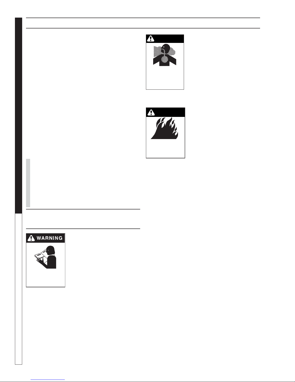
WARNING
WARNING: Risk of asphyxiation.
Use this product only in a well
ventilated area.
5. Avoid installing machines in
small areas or near exhaust
RISK OF
ASPHYXIATION: USE
THIS PRODUCT ONLY
IN A WELL
VENTILATED AREA.
fans. Exhaust contains poisonous carbon monoxide
gas; exposure may cause loss
of consciousness and may
lead to death. It also contains
chemicals known, in certain quantities, to cause
cancer, birth defects or other reproductive harm.
WARNING
WARNING: Risk of fi re. Do not
add fuel when the product is
operating.
WARNING: Risk of explosion —
do not spray fl ammable liquids.
RISK OF FIRE.
DO NOT ADD FUEL
WHEN OPERATING
MACHINE.
6. Do not place machine near
fl ammable objects as the engine is hot.
WARNING: This product contains
chemicals known to the state of California to cause
cancer and birth defects or other reproductive harm.
Operation of this equipment may create sparks that
can start fi res around dry vegetation. A spark arrestor may be required. The operator should contact:
Local fi re agencies for laws or regulations relating
to fi re prevention requirements.
IMPORTANT SAFETY
INFORMATION
WARNING: To reduce the risk of
injury, read operating instructions carefully before using.
1. Read the owner's manual
thoroughly. Failure to follow
instructions could cause mal-
READ OPERATOR’S
MANUAL THOROUGHLY
PRIOR TO USE.
2. Know how to stop the machine and bleed pressure
quickly. Be thoroughly familiar with the controls.
3. Stay alert — watch what you are doing.
4. All installations must comply with local codes.
Contact your electrician, plumber, utility company
or the selling distributor for specifi c details.
function of the machine and
result in death, serious bodily
injury and/or property damage.
7. Allow engine to cool for 1-2 minutes before refueling. If
any fuel is spilled, make sure the area is dry before
testing the spark plug or starting the engine. (Fire
and/or explosion may occur if this is not done.)
Gasoline engines on mobile or portable equipment
shall be refueled:
a. outdoors;
b. with the engine on the equipment stopped;
c. with no source of ignition within 10 feet of
the dispensing point; and
d. with an allowance made for expansion of the
fuel should the equipment be exposed to a
higher ambient temperature.
In an overfi lling situation, additional precautions are
necessary to ensure that the situation is handled
in a safe manner.
WARNING: Risk of injury. Disconnect battery
ground terminal before servicing.
8. Transport/repair with fuel tank EMPTY or with fuel
shut-off valve OFF.
4
BG • 8.919-012.0 • Rev. 08/12
Page 5
IMPORTANT SAFETY INFORMATION
PRESSURE WASHER
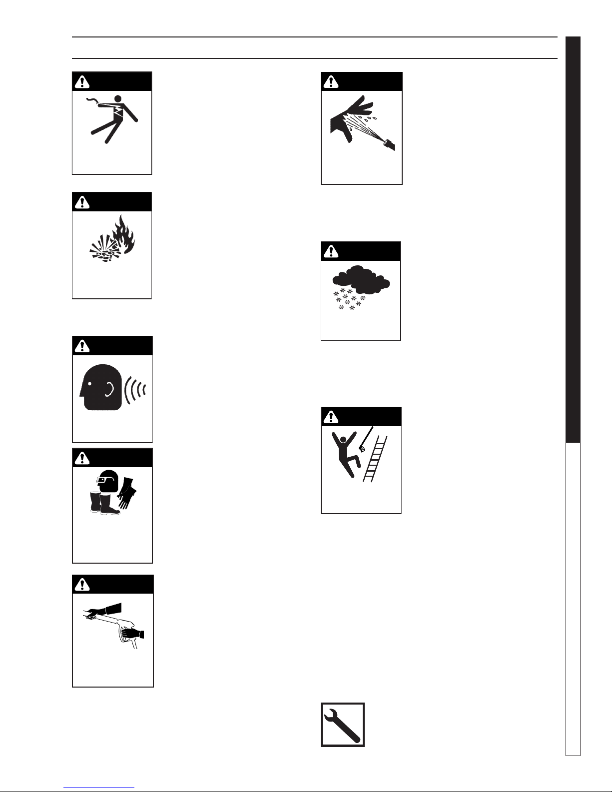
WARNING
WARNING: Keep wand, hose, and
water spray away from electric
wiring or fatal electric shock may
result.
9. Do not spray water on or near
electrical components.
KEEP WATER
SPRAY AWAY FROM
ELECTRICAL WIRING.
WARNING
WARNING: Flammable liquids
can create fumes which can ignite, causing property damage
or severe injury.
WARNING: Risk of explosion —
RISK OF EXPLOSION:
DO NOT SPRAY
FLAMMABLE
LIQUIDS.
Do not spray fl ammable liquids.
10. Keep operating area clear of
all persons.
WARNING
WARNING: This machine exceeds
85 db appropriate ear protection
must be worn.
EAR PROTECTION
MUST BE WORN
WARNING
WARNING: High pressure spray
can cause paint chips or other
particles to become airborne
and fl y at high speeds. To avoid
personal injury, eye, hand and
foot safety devices must be
USE PROTECTIVE
EYE WEAR
AND CLOTHING
WHEN OPERATING
THIS EQUIPMENT.
worn.
11. Eye, hand, and foot protection
must be worn when using this
equipment.
WARNING
WARNING: Grip cleaning wand
securely with both hands before
starting. Failure to do this could
result in injury from a whipping
wand.
12. To reduce the risk of injury,
TRIGGER GUN KICKS
BACK - HOLD WITH
BOTH HANDS
close supervision is necessary
when a machine is used near
children. Do not allow children
to operate the pressure washer. This machine
must be attended during operation.
WARNING
WARNING: High pressure developed by these machines will
cause personal injury or equipment damage. Keep clear of
nozzle. Use caution when operating. Do not direct discharge
RISK OF INJECTION
OR SEVERE INJURY
TO PERSONS. KEEP
CLEAR OF NOZZLE.
stream at people, or severe injury or death will result.
13. Never make adjustments on
machine while in operation.
14. Be certain all quick coupler fi ttings are secured
before using pressure washer.
WARNING
WARNING: Protect machine from
freezing.
15. To keep machine in best
operating conditions, it is
important you protect machine
from freezing. Failure to protect
PROTECT FROM
FREEZING
machine from freezing could
cause malfunction of the
machine and result in death,
serious bodily injury, and/or property damage. Follow storage instructions specifi ed in this manual.
16. The best insurance against an accident is precaution and knowledge of the machine.
WARNING
WARNING: Be extremely careful
when using a ladder, scaffolding
or any other relatively unstable
location. The cleaning area
should have adequate slopes
and drainage to reduce the possibility of a fall due to slippery
RISK OF INJURY
FROM FALLS WHEN
USING LADDER.
surfaces.
17. Do not overreach or stand on
unstable support. Keep good foot-
ing and balance at all times.
18. Do not operate this machine when fatigued or under
the infl uence of alcohol, prescription medications,
or drugs.
19. Inlet water must be clean fresh water and no hotter
then 90°F.
20. Manufacturer will not be liable for any changes
made to our standard machines or any components
not purchased from us.
21. Do not allow acids, caustic or abrasive fl uids to pass
through the pump.
22. Never run pump dry or leave spray gun closed
longer than 1-2 minutes.
Follow the maintenance instructions
specifi ed in the manual.
OPERATOR’S MANUAL
5
BG • 8.919-012.0 • Rev. 08/12
Page 6
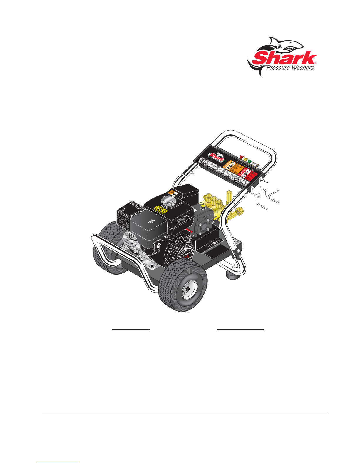
COMPONENT IDENTIFICATION
Unloader
Pump Protector
Pump
PRESSURE WASHER
OPERATOR’S MANUAL
High Pressure
Hose
Straight
Through
Starter Grip
Wand
Detergent
Injector
Inlet
Screen
Pressure
Nozzle
Garden Hose
(not included)
Detergent
Bucket (not
included)
Pump — Develops high pressure.
Starter Grip— Used for starting the engine manu-
ally.
Spray Gun — Controls the application of water and
detergent onto cleaning surface with trigger device.
Includes safety latch.
Detergent Injector — Allows you to siphon and mix
detergents.
6
Wand — Must be connected to the spray gun.
High Pressure Hose — Connect one end to water
pump discharge nipple (detergent injector nipple) and
the other end to spray gun.
Note: If trigger on spray gun is released for more
than 1-2 minutes, water may leak from pump protector. Warm water will discharge from pump protector
onto fl oor. This system prevents internal pump
damage from high temperatures.
BG • 8.919-012.0 • Rev. 08/12
Page 7
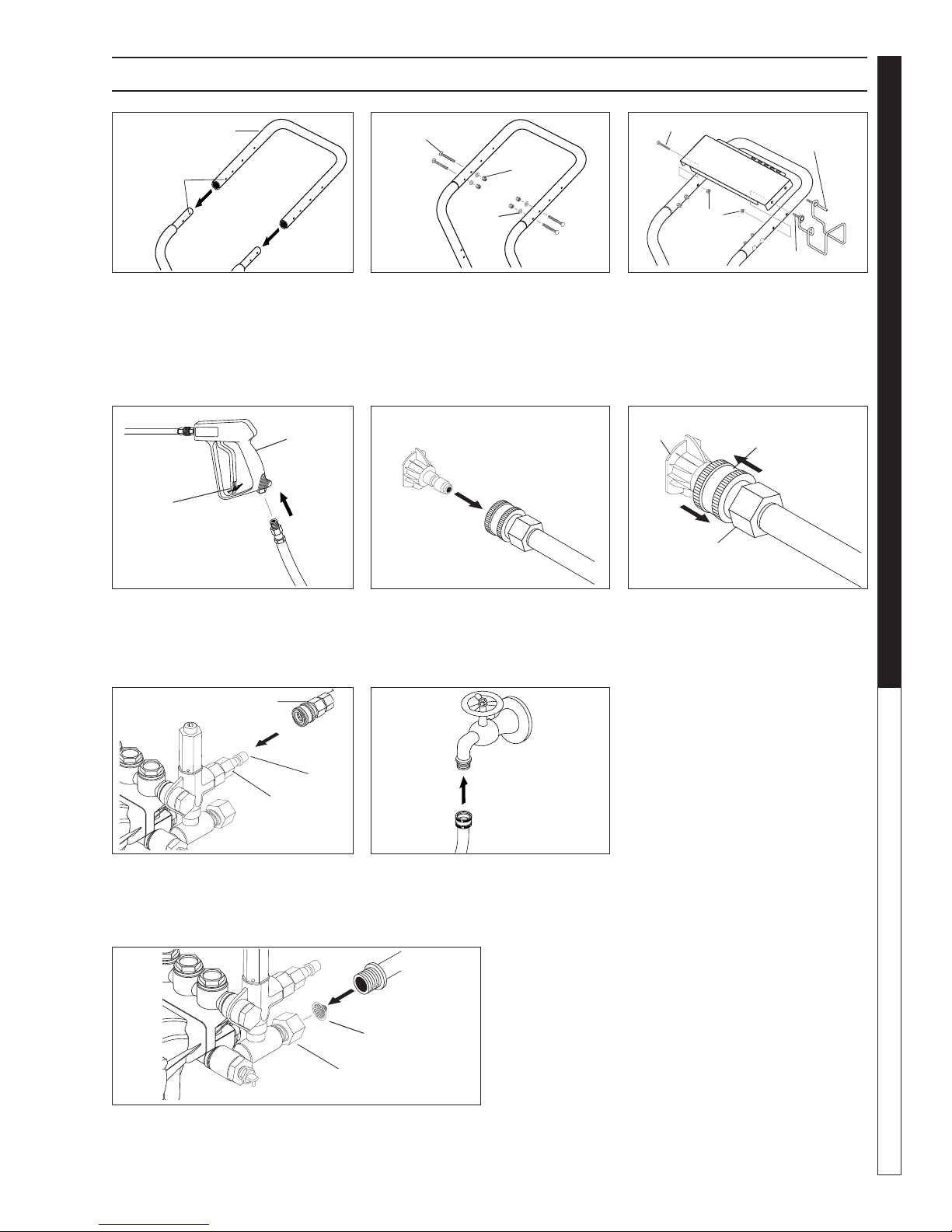
ASSEMBLY INSTRUCTIONS
PRESSURE WASHER
Handle
Alignment
Holes
Frame
Assy.
STEP 1: Attach the handle to the
frame of the pressure washer. Note:
It may be necessary to move the
handle supports from side to side
in order to align the handle so it will
slide over the frame supports.
Spray
Gun
Safety
Latch
High Pressure
Hose
Carriage
Bolt
Nut
Washer
STEP 2: Insert the carriage bolt
through the holes from the outside
of the unit and attach a nut from
the inside of the machine. Tighten
nuts.
Pressure
Nozzle
Wand
Coupler
Bolts
Nut
Hose/Spray Gun
Storage Bracket
Studs
STEP 3: Attach the spray gun/hose
storage handle, and bracket to
handle. Tighten nuts.
Pressure
Nozzle
Wand
Collar
Wand
Coupler
OPERATOR’S MANUAL
STEP 4: Attach the high pressure
hose to the spray gun using tefl on
tape on hose threads.
High Pressure Hose
Coupler
Collar
Pump
Discharge
Fitting
STEP 7: Connect high pressure
hose to pump discharge fitting.
Push coupler collar forward until
secure.
STEP 5: Pull the spring-loaded
collar of the wand coupler back
to insert your choice of pressure
nozzle.
Cold
Water
Source
Garden
Hose
STEP 8: Connect garden hose to a
clean cold water source and open
supply valve completely. NEVER
use hot water.
Garden
Hose
Inlet Screen
STEP 6: Release the coupler col-
lar and push the nozzle and the
collar until the collar clicks or locks.
Pull the nozzle to make sure it is
secure.
STEP 9: Connect the garden hose to pump water inlet.
Inspect inlet screen.
CAUTION: Do not run the pump
without water or pump damage will result.
Pump
Water Inlet
7
BG • 8.919-012.0 • Rev. 08/12
Page 8
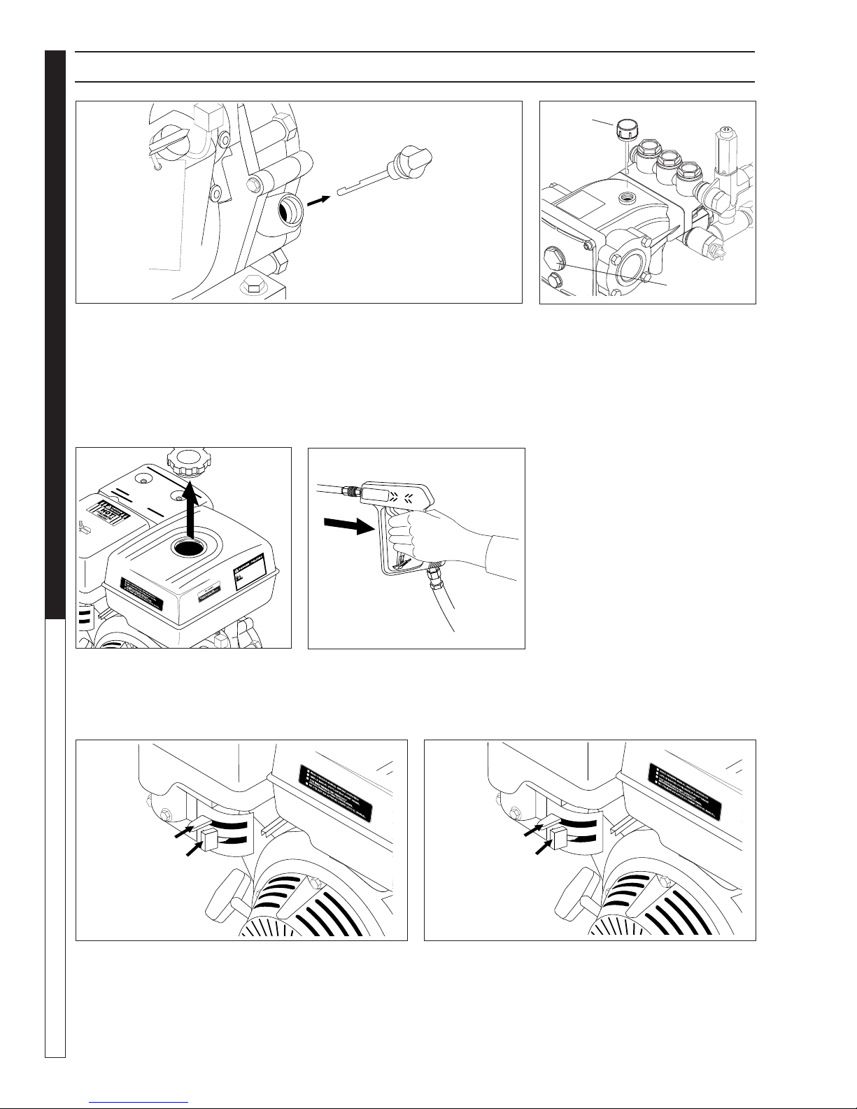
OPERATING INSTRUCTIONS
Pump Oil
Dipstick
Engine Oil
Dipstick
PRESSURE WASHER
Oil Window
STEP 1: Check engine oil level. Oil level should be level with the bottom
of the oil fi ller neck. Be sure the machine is level when checking the oil
level. (Refer to the engine's operating manual included with machine.) We
recommend that the oil be changed after the fi rst 5 hours of use, then once
OPERATOR’S MANUAL
every 50 hours. Note: Improper oil levels will cause low oil sensor to shut
off engine. IMPORTANT! Do not run engine with high or low oil levels
as this will cause engine damage.
Gas
Tank
STEP 3: Fill gas tank with unleaded
gasoline. Do not use leaded gasoline.
STEP 4: Trigger the spray gun to
eliminate trapped air then wait for a
steady fl ow of water to emerge from
the spray nozzle.
STEP 2: Remove shipping cap and
install oil dipstick. Check pump oil
level by using dipstick or observe oil
level in oil window (if equipped). Use
30 wt. (non detergent) oil.
Choke
Fuel
Valve
STEP 5: Move the fuel shut-off valve to the "On" posi-
tion. When the engine is not in use, leave the fuel valve
in the "OFF" position.
8
Choke
Lever
Fuel
Valve
STEP 6: Move the choke lever to the "Choke" position
(on a warm engine, leave the choke lever in the run
position). Move the choke lever to the "Closed" position.
To restart a warm engine, leave the choke lever in the
"Open" position.
BG • 8.919-012.0 • Rev. 08/12
Page 9
OPERATING INSTRUCTIONS (CONT.)
On-Off
Switch
PRESSURE WASHER
OPERATOR’S MANUAL
STEP 7: Turn the engine switch to "On" position.
On Briggs engines, move the throttle lever to "Fast"
position, shown on engine as a rabbit.
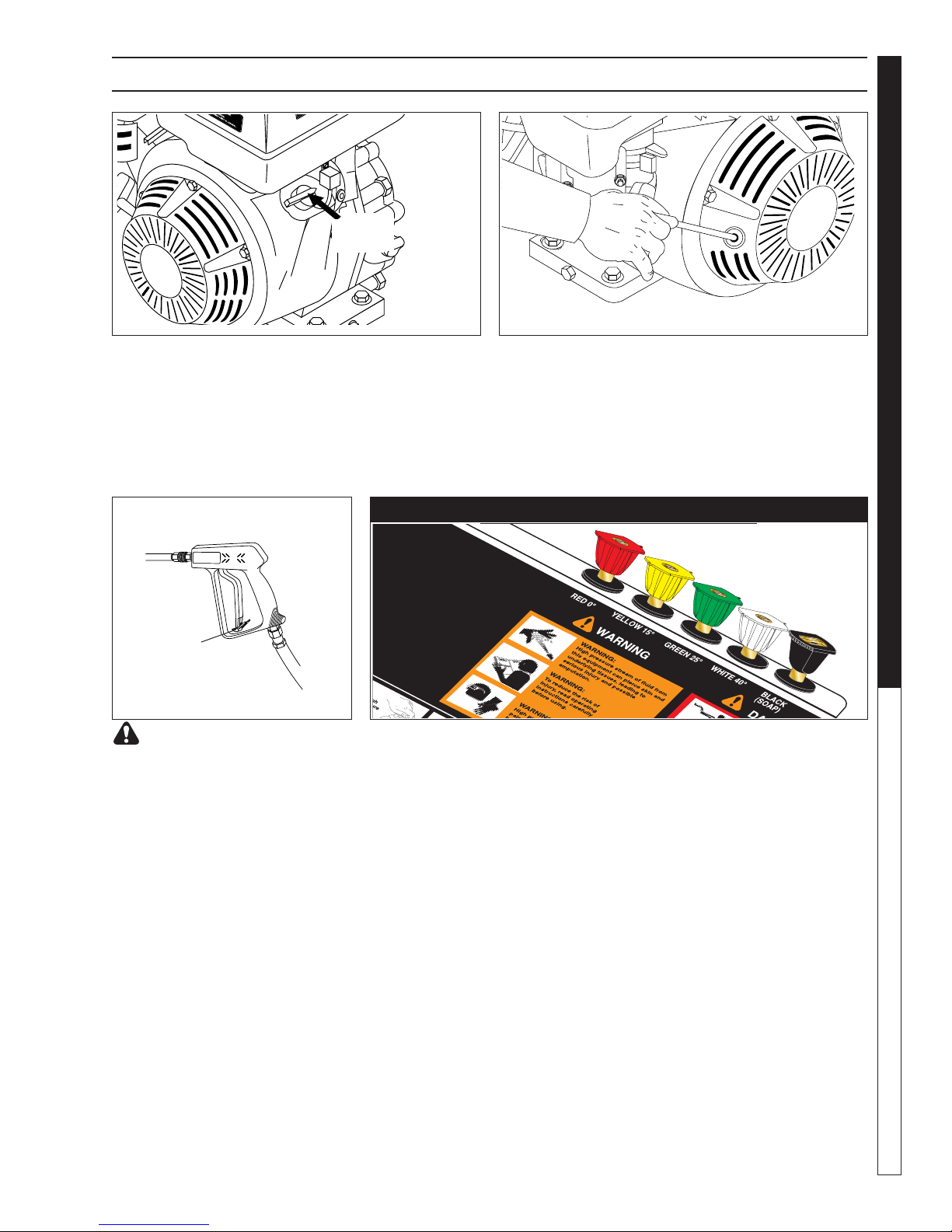
Safety
Latch
WARNING! Never replace
nozzles without engaging the
safety latch on the spray gun
trigger.
The fi ve color-coded quick connect nozzles provide a wide array of
spray widths from 0° to 40° and are easily accessible when placed in the
convenient rubber nozzle holder, which is provided on the front of the
machine.
NOTE: For a more gentle rinse, select the white 40° or green 25° nozzle.
To scour the surface, select the yellow 15° or red 0° nozzle. To apply detergent select the black nozzle.
STEP 8: Pull the starter grip. If the engine fails to start
after 2 pulls, squeeze the trigger gun to release pressure
and repeat step. Return starter gently. After the engine
warms up enough to run smoothly, move choke to run
position and throttle to fast position.
CAUTION: Small engines may kick back. Do not hold
pull starter grip tightly in hand.
NOZZLES
9
BG • 8.919-012.0 • Rev. 08/12
Page 10
WARNING
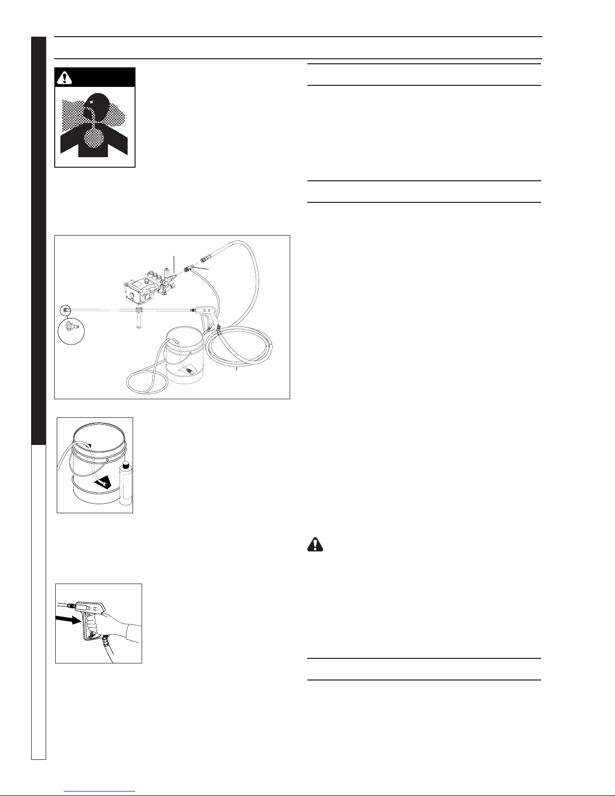
DETERGENTS & GENERAL CLEANING TECHNIQUES
WARNING: Some detergents
may be harmful if inhaled or
ingested, causing severe nausea, fainting or poisoning. The
harmful elements may cause
property damage or severe
injury.
PRESSURE WASHER
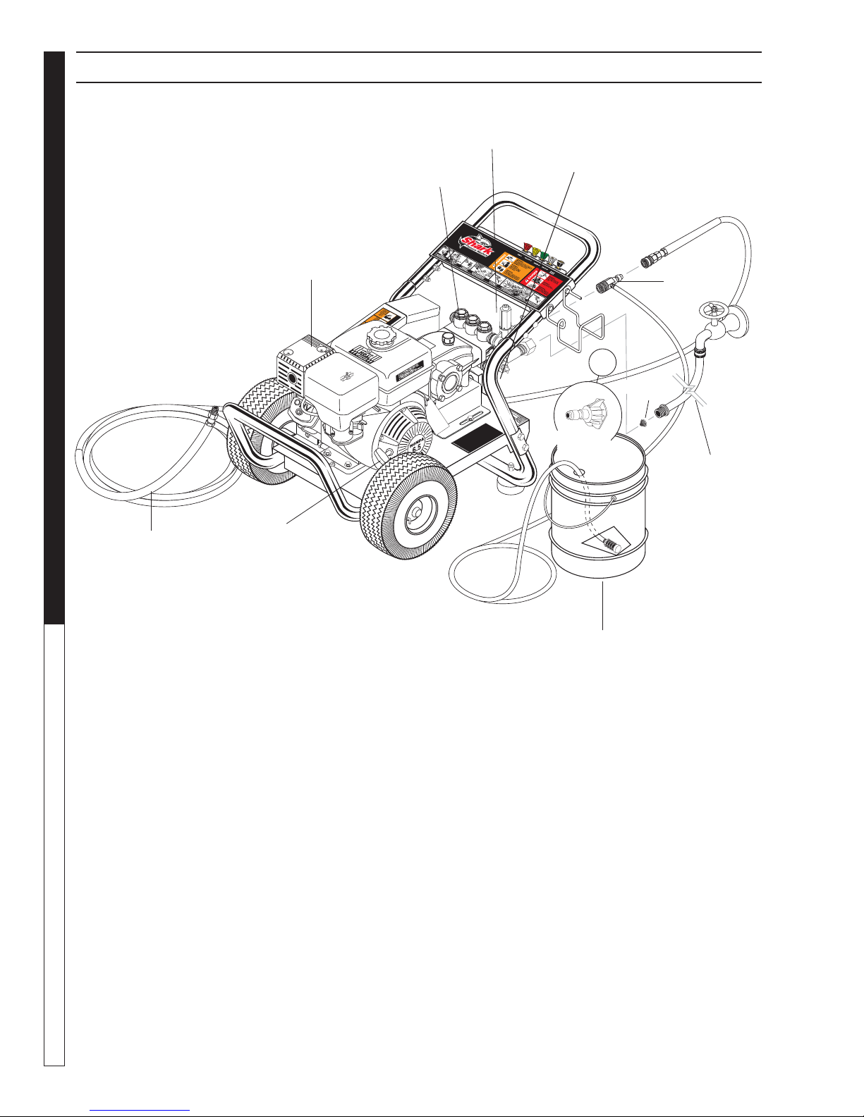
STEP 1: Connect detergent injector to discharge
nipple on machine. Connect high pressure hose to
injector with quick coupler. (Check to make sure locking couplers are in proper position before applying
water pressure).
Discharge
Nipple
OPERATOR’S MANUAL
STEP 2: Use detergent designed
specifi cally for pressure washers.
Household detergents could damage the pump. Prepare detergent
solution as required by the manufacturer. Fill a container with pressure washer detergent. Place the
fi lter end of detergent suction tube
into the detergent container.
STEP 3: With safety latch on spray
gun engaged, secure black detergent nozzle into quick
coupler.
NOTE: Detergent cannot be applied using red, yellow,
green or white nozzles.
STEP 4: With the engine running, pull trigger to operate machine. Liquid detergent is drawn
into the machine and mixed with
water. Apply detergent to work
area. Do not allow detergent to
dry on surface.
IMPORTANT: You must fl ush the detergent injection
system after each use by placing the suction tube
into a bucket of clean water, then run the pressure
washer in low pressure for 1-2 minutes.
10
Detergent
Injector
High Pressure
Hose
BG • 8.919-012.0 • Rev. 08/12
THERMAL PUMP PROTECTION
If you run the engine on your pressure washer for 1-2
minutes without pressing the trigger on the spray gun,
circulating water in the pump can reach high temperatures. When the water reaches this temperature, the
pump protector engages and cools the pump by discharging the warm water onto the ground. This thermal
device prevents internal damage to the pump.
CLEANING TIPS
Pre-rinse cleaning surface with fresh water. Place detergent suction tube directly into cleaning solution and
apply to surface at low pressure (for best results, limit
your work area to sections approximately 6 feet square
and always apply detergent from bottom to top). Allow
detergent to remain on surface 1-3 minutes. Do not allow detergent to dry on surface. If surface appears to
be drying, simply wet down surface with fresh water.
If needed, use brush to remove stubborn dirt. Rinse at
high pressure from top to bottom in an even sweeping
motion keeping the spray nozzle approximately 1 foot
from cleaning surface. Use overlapping strokes as you
clean and rinse any surface. For best surface cleaning
action spray at a slight angle.
Recommendations:
• Before cleaning any surface, an inconspicuous
area should be cleaned to test spray pattern and
distance for maximum cleaning results.
• If painted surfaces are peeling or chipping, use
extreme caution as pressure washer may remove
the loose paint from the surface.
• Keep the spray nozzle a safe distance from the
surface you plan to clean. High pressure wash a
small area, then check the surface for damage. If
no damage is found, continue to pressure washing.
CAUTION - Never use:
• Bleach, chlorine and other corrosive chemicals
• Liquids containing solvents (i.e., paint thinner,
gasoline, oils)
• Tri-sodium phosphate products
• Ammonia products
• Acid-based products
These chemicals will harm the machine and will damage the surface being cleaned.
RINSING
It will take a few seconds for the detergent to clear.
Apply safety latch to spray gun. Remove black soap
nozzle from the quick coupler. Select and install the
desired high pressure nozzle. NOTE: You can also stop
detergent from fl owing by simply removing detergent
siphon tube from bottle.
Page 11

SHUTTING DOWN AND CLEAN-UP
STEP 1: Remove detergent suc-
tion tube from container and insert
into one gallon of fresh water. Slide
nozzle forward for low pressure or to
connect black detergent nozzle into
wand quick coupler. Pull trigger on
spray gun and siphon water for one
minute.
On-Off
Switch
STEP 2: Turn off the engine. STEP 3: Turn off wa-
ter supply.
High Pressure
Outlet
PRESSURE WASHER
OPERATOR’S MANUAL
Pump Water
Inlet
STEP 4: Press trigger
to release water pressure.
STEP 5: Disconnect the garden hose from the water inlet
on the machine.
STORAGE
CAUTION: Always store your pressure washer in a
location where the temperature will not fall below
32°F (0°C). The pump in this machine is susceptible
to permanent damage if frozen. FREEZE DAMAGE
IS NOT COVERED BY WARRANTY.
1. Stop the pressure washer, squeeze spray gun trigger to release pressure.
2.
Detach water supply hose and high pressure hose.
3. Turn on the machine for a few seconds, until remaining water exits. Turn engine off immediately.
4. Drain the gas and oil from the engine.
5. Do not allow high pressure hose to become
kinked.
6. Store the machine and accessories in a room which
does not reach freezing temperatures.
CAUTION: Failure to follow the above directions will
result in damage to your pressure washer.
When the pressure washer is not being operated or is
being stored for more than one month, follow these
instructions:
1. Replenish engine oil to upper level.
2. Drain gasoline from fuel tank, fuel line, fuel valve
and carburetor.
3. Pour about one teaspoon of engine oil through the
spark plug hole, pull the starter grip several times
and replace the plug. Then pull the starter grip
BG • 8.919-012.0 • Rev. 08/12
Safety Latch
STEP 6: Disconnect the high
pressure hose from high pressure outlet.
slowly until you feel increased pressure which indicates the piston is on its compression stroke and
leave it in that position. This closes both the intake
and exhaust valves to prevent rusting of cylinder.
4. Cover the pressure washer and store in a clean,
dry place that is well ventilated away from open
fl ame or sparks. NOTE: The use of a fuel additive,
such as STA-BIL
the formulation of fuel deposits during shortage.
Such additives may be added to the gasoline in
the fuel tank of the engine, or to the gasoline in a
storage container.
®
, or an equivalent, will minimize
STEP 7: Engage
the spray gun safety
lock.
After Extended Storage
CAUTION: Prior to restarting, thaw out any
possible ice from pressure washer hoses,
spray gun or wand.
Engine Maintenance
During the winter months, rare atmospheric conditions
may develop which will cause an icing condition in the
carburetor. If this develops, the engine may run rough,
lose power and may stall. This temporary condition can
be overcome by defl ecting some of the hot air from the
engine over the carburetor area. NOTE: Refer to the
engine manufacturer's manual for service and maintenance of the engine.
11
Page 12

TROUBLESHOOTING
PROBLEM POSSIBLE CAUSE SOLUTION
LOW OPERATING
PRESSURE
Faulty pressure gauge Install new gauge.
Insuffi cient water supply
Use larger supply hose; clean fi lter at
water inlet.
PRESSURE WASHER Troubleshooting Guide
Old, worn or incorrect spray nozzle
Belt slippage Tighten or replace; use correct belt.
Plumbing or hose leak
Faulty or mis-adjusted unloader valve
Worn packing in pump Install new packing kit.
Fouled or dirty inlet or discharge valves
in pump
Worn inlet or discharge valves Replace with valve kit.
Obstruction in spray nozzle Remove obstruction.
Leaking pressure control valve Rebuild or replace as needed.
Slow engine RPM Set engine speed at proper specifi cations.
Pump sucking air
Valves sticking Check and clean or replace if necessary.
Match nozzle number to machine and/or
replace with new nozzle.
Check plumbing system for leaks. Re-tape
leaks with tefl on tape.
Adjust unloader for proper pressure. Install
repair kit when needed.
Clean inlet and discharge valves.
Check water supply and possibility of air
seepage.
Unloader valve seat faulty Check and replace if necessary.
FLUCTUATING
PRESSURE
Valves worn Check and replace if necessary.
Blockage in valve
Pump sucking air
Worn piston packing Check and replace if necessary.
ADJUSTING UNLOADER VALVES
Unloader valves are preset and tested at the factory
before shipping. Occasional adjustment of the unloader
may be necessary to maintain correct pressure.
Start with the valve set at its lowest spring tension. Raise
pressure by turning adjusting knob clockwise until pressure is at the desired position. Do not overtighten.
Check and replace if necessary.
Check water supply and air seepage at
joints in suction line.
Open and close spray gun to be sure pressure is correct.
Raise or lower pressure by adjusting the knob.
Do not by-pass more than 1-2 minutes when by-passing
to the suction side of the pump.
12
BG • 8.919-012.0 • Rev. 08/12
Page 13

PREVENTATIVE MAINTENANCE
This pressure washer was produced with the best available materials and quality craftsmanship. However, you
as the owner have certain responsibilities for the correct care of the equipment. Attention to regular preventative
maintenance procedures will assist in preserving the performance of your equipment. Contact your dealer for
maintenance. Regular preventative maintenance will add many hours to the life of your pressure washer. Perform
maintenance more often under severe conditions.
PRESSURE WASHER
Maintenance Operation Every 8 Hrs
or Daily
Check Oil
Change Oil
Air Cleaner Check Clean
Spark Plug
Check Valve Clearance
Fuel Tank Filter
Water Filter/Clean Check
Pump
Engine
Pump
Engine
X
25 Hrs or
Weekly
X
50 Hrs or
Monthly
X
OIL CHANGE RECORD
100 Hrs or
Yearly
X
X
Yearly
X
X
X
OPERATOR’S MANUAL
Check pump oil and engine oil level before fi rst use of your new pressure washer.
Date Oil Changed
Month/Day/Year
No. of Operating Hours
Since Last Oil Change
BG • 8.919-012.0 • Rev. 08/12
Type of Oil (see above)
Brand Name and
13
Page 14

“This pr
oduct contains chemicals kno
wn to the State of
Calif
ornia to cause cancer and bi
r
t
h defects or other
repr
oductive harm.
Operation of
This Equipment Ma
y
Create Sparks
That Can Star
t Fires Ar
ound Dry
V
e
g
e
tat
i
on
.
A Spark Arrestor Ma
y be Required.
The Operator Should
Contact Local Fire Agencies for Laws or Regulations
Relating to Fire Pre
vention Requirements.
”
WARNING
8.917-0
1
5.0
EXPLODED VIEW - 1.107-142.0, 1.107-143.0
PRESSURE WASHER
26
OPERATOR’S MANUAL
38
29
49
7
57
33
27
38
29
51
50
48
47
66
15
36
52
58
36
38
29
65
54
46
28
41
58
36
30
60
42
31
40
62
29
44
43
45
35
61
60
6
57
9
1
2
32
3
4
60
61
61
61
60
5
64
21
24
22
53
23
36
37
14
25
36
34
8
60
61
56
55
36
20
37
21
BG • 8.919-012.0 • Rev. 08/12
59
11
64
12
63
11
19
17
6
10
13
14
12
16
39
18
Page 15

EXPLODED VIEW PARTS LIST - 1.107-142.0, 1.107-143.0
ITEM PART NO. DESCRIPTION QTY
1 9.802-064.0 Grommet, Rubber, Nozzle Holder 5
2 8.920-262.0 Handle, Grab, Chrome 1
3 8.900-909.0 Label, Cold Water Handle 1
4 9.803-126.0 Plate, Warning/Instructions, Black 1
5 9.803-098.0 Hanger, Hose/Wand 1
6 9.802-706.0 Bolt, Carriage, 1/4"-20 x 1-3/4", Zinc 6
7 8.900-870.0 Label, Shark Logo 1
8 9.802-741.0 Bolt, 8mm x 16mm Hex 4
9 9.802-778.0 Nut, 5/16" Whiz Loc Flange 2
10 8.920-261.0 Handle, Lower Grab, Chrome 1
11 9.197-003.0 Nut, 3/8", ESNA, NC 6
12 9.802-807.0 Washer, 3/8" SAE, Flat 6
13 9.803-114.0 Retainer Bracket, Handle, Black 2
14 9.802-728.0 Bolt, 3/8" x 2" NC, HH 4
15 9.802-713.0 Bolt, 5/16" x 1/2" 4
16 9.802-817.0 Washer, 3/8" x 1", Steel 2
17 9.802-066.0 Pad, Soft Rubber 2
18 9.802-782.0 Collar, 5/8" Bore Shaft, 3010 2
19 9.802-270.0 Wheel & Tire Assembly, 4" Steel Rim w/Tube 2
20 9.803-124.0 Frame Assy, Small, Black 1
21 9.802-712.0 Bolt, 5/16" x 1-3/4", NC, Carriage, Zinc 4
22 9.802-776.0 Nut, 5/16", ESNA, NC 4
23 8.718-980.0 Washer, 5/16" Flat, SAE 4
24 9.803-097.0 Axle, 5/8" x 19-5/8" 1
25 8.917-892.0 Slider, Pump, Black 1
26 8.917-885.0 Guard, Belt 1
27 Hose, See Hose & Spray Gun Assembly
28 9.803-118.0 Bracket, Take Up, CW, Black 1
29 9.802-700.0 Screw, 1/4" x 3/4" HH NC 6
30 9.802-809.0 Washer, 1/2", Flat, SAE 1
31 9.802-740.0 Bolt, 1/2" x 3-1/2" HEX 1
32 8.712-398.0 Nozzle, Compl., Detergent 1
33 9.800-036.0 Label, Warning, Pictorial Small 1
34 9.802-813.0 Washer, 5/16" Lock 4
35 9.802-225.0 Injector Assy, Detergent, Non-Adj, 3-5GPM 1
36 8.718-980.0 Washer, 5/16" Flat 18
37 9.802-776.0 Nut, 5/16" ESNA 7
38 9.802-802.0 Washer, 1/4" Flat, SAE 4
39 9.802-730.0 Bolt, 3/8" x 2-1/4", HH 2
40 9.804-025.0 Pump Protector 1/4" 1
41 Pump, See Specifi cations Pages
PRESSURE WASHER
OPERATOR’S MANUAL
15
BG • 8.919-012.0 • Rev. 08/12
Page 16

EXPLODED VIEW PARTS LIST - 1.107-142.0, 1.107-143.0
ITEM PART NO. DESCRIPTION QTY
42 Unloader, See Specifi cations Pages
43 9.802-171.0 Nipple, 3/8" x 3/8" NPT ST Male 1
44 9.802-146.0 Swivel, 1/2" MP x 3/4" GHF w/Strainer 1
45 9.802-163.0 Strainer, 1/2" PA, Inline Plastic 1
46 9.800-008.0 Label, Danger Cool Engine 1
47 Engine, See Specifi cations Pages
PRESSURE WASHER
48 Engine Pulley, See Specifi cations Pages
49 Engine Bushing, See Specifi cations Pages
50 Belts, See Specifi cations Pages
51 Pump Bushing, See Specifi cations Pages
52 Pump Pulley, See Specifi cations Pages
53 8.920-263.0 Handle, Bumper, Chrome 1
54 9.800-006.0 Label, Hot/Caliente w/Arrows, Warning 1
55 8.932-968.0 Label, Intended For Outdoor Use 1
OPERATOR’S MANUAL
56 9.800-034.0 Label, Clear Lexan, 2-1/4" x 4-1/2" 1
57 8.712-331.0 Nozzle, SAQCMEG, 0003.0, Red (143.0) 1
8.712-333.0 Nozzle, SAQCMEG 1503.0, Yellow (143.0) 1
8.712-334.0 Nozzle, SAQCMEG, 2503.0, Green (143.0) 1
8.712-335.0 Nozzle, SAQCMEG 4003.0, White (143.0) 1
8.712-345.0 Nozzle, SACQMEG, 0004.5, Red (142.0) 1
8.712-346.0 Nozzle, SAQCMEG 1504.0, Yellow (142.0) 1
8.712-347.0 Nozzle, SAQCMEG, 2504.0, Green (142.0) 1
8.712-348.0 Nozzle, SAQCMEG 4004.0, White (142.0) 1
58 9.802-710.0 Bolt, 5/16" x 1" NC 3
59 9.802-103.0 Bushing, 5/8" Snap 2
60 9.802-802.0 Washer, 1/4" Flat, SAE 10
61 9.802-773.0 Nut, 1/4" ESNA, NC 8
62 8.706-829.0 Elbow, 1/2"" Street, Brass 1
63 9.800-049.0 Label, Manufacturer's Cleaning Solution 1
64 9.802-810.0 Washer, 5/8" Flat 2
65 9.802-958.0 Key, .185 Sqr. x 1.75" 1
66 8.751-096.0 Label, Regulation 4442.6 1
▲ Not Shown
16
BG • 8.919-012.0 • Rev. 08/12
Page 17

“Th
i
s
p
r
oduct conta
i
ns c
h
em
i
cals
kn
o
w
n
to the State of
Calif
ornia to cause cancer and bi
r
t
h defec
t
s or other
repr
odu
cti
ve
har
m
.
Operation of
This Equipment Ma
y
Create Sparks
That Can Star
t
F
i
res
Ar
ou
n
d Dr
y
V
e
g
e
t
at
i
on
.
A
S
p
a
r
k
Arrestor Ma
y be
R
equ
i
re
d.
The Operator Should
Contact Local Fire Agencies for Laws o
r Regulations
Rel
a
t
i
ng to
F
ire
Pr
e
vention Requirements.
”
WARNIN
G
8.917
-0
15.0
EXPLODED VIEW - 1.107-144.0, 145.0, 146.0, 159.0
PRESSURE WASHER
30
30
62
25
37
32
Pump
144.0
7
69
51
49
50
28
38
39
36
52
91
67
Pump
146.0
46
75
41
74
80
76
79
72
86
77
78
73
45
89
41
44
43
40
88
82
81
42
42
87
65
43
37
45
39
44
38
32
36
32
35
26
57
OPERATOR’S MANUAL
64
48
47
54
11
14
60
90
61
24
61
60
61
27
60
70
29
58
28
30
6
59
58
6
58
58
59
59
58
34
8
57
1
68
2
3
4
23
20
53
22
21
11
21
10
11
22
70
33
63
59
11
58
56
55
19
20
10
BG • 8.919-012.0 • Rev. 08/12
10
10
11
66
18
16
11
17
6
9
5
10
12
13
15
31
17
Page 18

EXPLODED VIEW PARTS LIST - 1.107-144.0, 145.0, 146.0, 159.0
ITEM PART NO. DESCRIPTION QTY
1 9.802-064.0 Grommet, Rubber, Nozzle Holder 5
2 8.920-262.0 Handle, Grab, Chrome 1
3 8.900-909.0 Label, Cold Water Handle 1
4 9.803-126.0 Plate, Warning/Instruction, Black 1
5 9.803-098.0 Hanger, Hose/Wand 1
6 9.802-706.0 Bolt, Carriage, 1/4"-20 x 1-3/4", Zinc 6
PRESSURE WASHER
7 8.900-870.0 Label, Shark Logo 1
8 9.802-778.0 Nut, 5/16" Whiz Loc Flange 2
9 8.920-261.0 Handle, Lower Grab, Chrome 1
10 9.197-003.0 Nut, 3/8" ESNA, NC 10
11 9.802-807.0 Washer, 3/8" SAE, Flat 14
12 9.803-114.0 Retainer Bracket, Handle, Black 2
13 9.802-728.0 Bolt, 3/8" x 2" NC, HH 4
14 9.802-727.0 Bolt, 3/8" x 1-3/4", Tap 4
OPERATOR’S MANUAL
15 9.802-817.0 Washer, 3/8" x 1", Steel 2
16 9.802-066.0 Pad, Soft Rubber 2
17 9.802-782.0 Collar, 5/8" Bore Shaft, 3010 2
18 9.802-271.0 Wheel & Tire Assy, 13" Steel Rim w/Tube 2
19 9.803-115.0 Frame Assy, Large, Black 1
20 9.802-712.0 Bolt, 5/16" x 1-3/4", NC, Carriage, Zinc 4
21 9.802-776.0 Nut, 5/16", ESNA, NC 4
22 8.718-980.0 Washer, 5/16" Flat, SAE 4
23 8.911-226.0 Axle, 5/8" x 27" L 1
24 8.917-893.0 Assy Black, Slider Pump / Belt Guard Mount 1
25 8.917-886.0 Plate, Belt Guard Front Cover 1
26 Hose, See Hose and Spray Gun Assy.
27 9.803-118.0 Bracket, Take Up, CW, Black 1
28 9.802-700.0 Screw, 1/4" x 3/4" HH NC 8
29 9.802-809.0 Washer, 1/2", Flat, SAE 1
30 9.802-740.0 Bolt, 1/2" x 3-1/2" HEX 1
31 9.802-730.0 Bolt, 3/8" x 2-1/4", HH 2
32 6.390-126.0 Clamp, Hose, .46-54 ST 2
33 9.802-813.0 Washer, 5/16" Lock (144.0) 4
9.802-816.0 Washer, 7/16" Lock, Split (145.0, 146.0, 159.0) 4
34 9.802-225.0 Injector Assy., Detergent, Non-Adj, 3-5 GPM, 0.083 1
35 9.802-254.0 Hose, 1/4", Push-On, Fuel Line(All except 146.0) 1 ft.
36 8.706-958.0 Barb, 1/4" Barb x 1/4" ML Pipe, 90° 1
37 8.706-955.0 Hose Barb, 1/4" Barb x 1/8" ML Pipe 90° (144.0) 1
8.706-940.0 Hose Barb, 1/4" Barb x 1/8" ML Pipe (145.0, 146.0, 159.0) 1
18
BG • 8.919-012.0 • Rev. 08/12
Page 19

EXPLODED VIEW PARTS LIST - 1.107-144.0, 145.0, 146.0, 159.0
ITEM PART NO. DESCRIPTION QTY
38 9.802-190.0 Valve, E-Z Start, 3/8" MPT x 1/8" FPT (145.0, 159.0) 1
9.804-065.0 Valve, E-Z Start, 1/4" MPT x 1/8" FPT (144.0) 1
39 8.706-207.0 Elbow, 3/8", Street 1
8.706-200.0 Elbow, 1/4", Street (144.0) 1
40 9.804-025.0 Pump Protector, 1/4" PTP (All except 146.0) 1
41 Pump, See Specifi cations Pages
42 Unloader, See Specifi cations Pages
43 9.802-171.0 Nipple, 3/8" x 3/8" NPT ST Male 1
44 9.802-146.0 Swivel, 1/2" MP x 3/4" GHF w/Strainer 1
45 9.802-163.0 Strainer, 1/2" PA, Inline Plastic 1
46 9.800-008.0 Label, Danger Cool Engine 1
47 Engine, See Specifi cations Pages
48 Engine Pulley, See Specifi cations Pages
49 Engine Bushing, See Specifi cations Pages
50 Belts, See Specifi cations Pages
51 Pump Bushing, See Specifi cations Pages
52 Pump Pulley, See Specifi cations Pages
53 8.920-263.0 Handle, Bumper, Chrome 1
54 9.800-006.0 Label, Hot/Caliente w/Arrows, Warning 1
55 8.932-968.0 Label, Intended For Outdoor Use 1
56 9.800-034.0 Label, Clear Lexan, 2-1/4" x 4-1/2" 1
57 8.712-337.0 Nozzle, SAQCMEG, 0003.5, Red (144.0) 1
8.712-338.0 Nozzle, SAQCMEG 1503.5, Yellow (144.0) 1
8.712-339.0 Nozzle, SAQCMEG, 2503.5, Green (144.0) 1
8.712-340.0 Nozzle, SAQCMEG 4003.5, White (144.0) 1
8.712-345.0 Nozzle, SACQMEG, 0004, Red (145.0, 159.0) 1
8.712-346.0 Nozzle, SAQCMEG 1504, Yellow (145.0, 159.0) 1
8.712-347.0 Nozzle, SAQCMEG, 2504, Green (145.0, 159.0) 1
8.712-348.0 Nozzle, SAQCMEG 4004, White (145.0, 159.0) 1
8.712-331.0 Nozzle, SACQMEG, 0003 Red(146.0) 1
8.712-333.0 Nozzle, SAQCMEG 1503.0, Yellow (146.0) 1
8.712-334.0 Nozzle, SAQCMEG, 2503.0, Green (146.0) 1
8.712-335.0 Nozzle, SAQCMEG 4003.0, White(146.0) 1
58 9.802-802.0 Washer, 1/4" Flat 10
59 9.802-773.0 Nut, 1/4" ESNA 8
60 8.718-980.0 Washer, 5/16" Flat 4
61 9.802-776.0 Nut, 5/16" ESNA 4
62 9.802-802.0 Washer, 1/4" Flat, SAE 6
63 9.802-741.0 Bolt, 8mm x 16mm Hex (144.0) 4
9.802-744.0 Bolt, 10mm x 20mm (145.0,146.0, 159.0) 4
64 8.706 -860.0 Tee, 1/2" Branch (146.0) 1
8.706-854.0 Tee, 1/4" Branch (144.0, 145.0, 159.0) 1
65 8.706-984.0 Adapter, 1/2" x 1/2" (All except 145.0, 146.0) 1
66 9.800-049.0 Label, Manufacturer's Cleaning Solution 1
67 9.802-959.0 Key, .247 Sqr. x 2.125" 1
68 8.712-398.0 Nozzle, Compl., Detergent 1
69 9.800-036.0 Label, Warning, Pictoral, Small 1
PRESSURE WASHER
OPERATOR’S MANUAL
19
BG • 8.919-012.0 • Rev. 08/12
Page 20

EXPLODED VIEW PARTS LIST - 1.107-144.0, 145.0, 146.0, 159.0
ITEM PART NO. DESCRIPTION QTY
70 8.718-980.0 Washer, 5/16" Flat (144.0) 4
9.802-807.0 Washer, 3/8" Flat (146.0) 4
71 8.750-300.0 Unloader, VRT3 Ez Start (146.0) 1
72 9.802-870.0 Block, Unloader, 3/8" x 3/8" 1.25 Stee (146.0) 1
73 9.802-728.0 Bolt, 3/8" x 2", NC HH (146.0) 2
74 9.802-807.0 Washer, 3/8" SAE, Flat (146.0) 2
75 9.197-003.0 Nut, 3/8" ESNA NC (146.0) 2
PRESSURE WASHER
76 8.705-974.0 Nipple, 3/8" Hex Steel (146.0) 1
77 9.802-129.0 Elbow, 3/8" x 1/2" JIC (146.0) 1
78 8.706-860.0 Street Tee, 1/2" (146.0) 1
79 9.802-128.0 Nipple, 1/2" x 1/2" JIC (146.0) 1
80 9.802-259.0 Hose, Push-on 1/2" (146.0) 15"
81 8.707-254.0 Pump Protector, 3/8" PTP (146.0) 1
82 9.802-036.0 Nipple, 1/2" JIC, 3/8" Pipe (146.0) 1
OPERATOR’S MANUAL
83 9.802-810.0 Washer, 5/8" Flat 2
84 9.802-151.0 Swivel, 1/2" JIC, Female, Push-On (146.0) 2
85 9.802-959.0 Key, .247" Sqr. x 2.125" 1
86 9.800-036.0 Label, Warning, Pictoral, Small 1
87 9.802-039.0 Elbow, 1/2" JIC, 3/8", 90° (146.0) 1
88 8.918-221.0 Hose, 3/8" x 20", 5800, 2 Wire, Pressure Loop (146.0) 1
89 8.706-829.0 Elbow, 1/2"" Street Brass" 1
90 8.751-096.0 Label, Regulation 4442.6 1
91 8.917-889.0 Plate, Belt Guard Back Cover 1
8.920-542.0 Black Plate Belt Guard (144.0) 1
▲ Not Shown
20
BG • 8.919-012.0 • Rev. 08/12
Page 21

HOSE & SPRAY GUN ASSEMBLY
2
PRESSURE WASHER
1
12
11
5
9
6
7
8
4
10
3
OPERATOR’S MANUAL
HOSE & SPRAY GUN ASSEMBLY PARTS LIST
ITEM PART NO. DESCRIPTION QTY
1 9.802-219.0 Wand Assy., Side Grip w/1/4" Coupler, 35-1/2" 1
2 8.710-384.0 Gun, St-1500, 5000 PSI, 10.4 Gpm 1
3 9.802-164.0 Coupler, 1/4” Female, Brass 1
4 Nozzle, See Breakdown for Part Numbers
5 8.739-125.0 Hose, 3/8" x 50', 1 Wire, Tuff-Flex, (142.0, 143.0, 144.0) 1
8.739-203.0 Hose, 3/8" x 50', 2 Wire,Tuff-Flex (145.0, 146.0) 1
8.917-059.0 Hose, 3/8" x 50, 2W, Tf, So-Sw, C&N (159.0) 1
6 9.802-166.0 Coupler, 3/8" Female, Brass 1
7 9.802-216.0 Injector, Chemical, Non-Adjust, 3-5 GPM, .083 1
8 6.390-126.0 Clamp, Hose 2
9 9.802-251.0 Tube, 1/4" x 1/2" Clear Vinyl 6 ft.
10 8.707-057.0 TStrainer, Plastic, 1/4" Hose Barb 1
11 9.802-170.0 Nipple 3/8 x 3/8 NPT Fem (146.0 Only) 1
12 9.802-169.0 Coupler 3/8" Male Brass (146.0 Only) 1
BG • 8.919-012.0 • Rev. 08/12
21
Page 22

SPECIFICATIONS
Pressure
Model GPM
1.107-142.0 2.8 2000 4.0 KD3030 9.804-006.0 9.175-018.0 GX160 (163cc) 9.802-316.0 AK74H 9.802-369.0
1.107-143.0 2.5 2700 3.0 KD3030 9.804-006.0 9.175-018.0 GX200 (196cc) 9.802-317.0 BK80H 9.802-380.0
1.107-144.0 3.0 3000 3.5 KD3030 9.804-006.0 9.175-018.0 GX270 (270cc) 8.750-680.0 2BK80 9.802-389.0
1.107-145.0 3.7 3500 4.0 KM4035R.3 8.751-189.0 9.175-018.0 GX390 (390cc) 8.750-580.0 2BK90H 8.715-593.0
1.107-146.0 3.0 4000 3.0 KM3540R.3 8.751-186.0 8.750-300.0 GX390 (390cc) 8.750-580.0 2BK80H 9.802-389.0
1.107-159.0 3.5 3200 4.0 KM4035R.3 8.751-189.0 9.803-900.0 GX390 (390cc) 8.750-580.0 2BK90H 8.715-593.0
(PSI)
Nozzle
Size Pump
Pump
Part No.
Unloader
Part No. Engine
Engine
Part No.
Pump
Pulley
Pump Pulley
PRESSURE WASHER Specifi cations
Part No.
22
BG • 8.919-012.0 • Rev. 08/12
Page 23

SPECIFICATIONS
PRESSURE WASHER Specifi cations
Pump
Model
1.107-142.0 24MM 9.802-402.0 AK39H 9.803-898.0 HX3/4" 9.803-897.0 AX33 (1) 9.803-896.0
1.107-143.0 24MM 9.802-402.0 BK36H 9.802-379.0 HX3/4" 9.803-897.0 BX32 (1) 9.802-413.0
1.107-144.0 24MM 9.802-402.0 2BK40H 9.802-384.0 HX1" 9.802-399.0 BX38 (2) 9.802-417.0
1.107-145.0 24MM 9.802-402.0 2BK32H 8.715-576.0 HX1" 9.802-399.0 BX39 (2) 9.802-418.0
1.107-146.0 24MM 9.802-402.0 2BK40H 9.802-384.0 HX1" 9.802-399.0 BX38 (2) 9.802-417.0
1.107-159.0 24MM 9.802-402.0 2BK32H 8.715-576.0 HX1" 9.802-399.0 BX39 9.802-418.0
Bushing
Bushing Part
No.
Engine
Pulley
Pulley
Part No.
Engine
Bushing
Bushing
Part No.
Belt
Size
Belt
Part No.
23
BG • 8.919-012.0 • Rev. 08/12
Page 24

8.751-189.0 KM4035R.3
8.751-186.0 KM3540R.3
PRESSURE WASHER
OPERATOR’S MANUAL
KM.3 SERIES PUMP EXPLODED VIEW
TORQUE
SPECS
Item # Ft.-lbs
14 75
15 30
23 8
33 9
43 13
48 7.6
KM.3 SERIES PUMP EXPLODED VIEW PARTS LIST
ITEM PART NO. DESCRIPTION QTY
1 8.751-216.0 Crankcase 1
2* See Kits Below Plunger Oil seal 3
3*
4*
5*
6*
7*
8 9.803-199.0 Washer, Copper 1
9
10 8.751-218.0 Manifold Head 1
11*
12*
13*
14 9.802-928.0 Valve Plug 6
15 9.802-938.0 Manifold Stud Bolt 8
16 9.802-884.0 Washer 16
17 9.803-198.0 Copper Washer 3/8 1
18 9.802-925.0 Brass Plug 3/8 2
See Kits Below
See Kits Below
See Kits Below
See Kits Below
See Kits Below
9.802-926.0 Plug, Brass 1/2
See Kits Below
See Kits Below Valve Assembly
See Kits Below
O-Ring Ø1.78 x 31.47 3
Pressure Ring 3
U-Seal 3
Intermediate Ring 3
U-Seal 3
O-Ring Ø2.62 x 17.13 6
O-Ring Ø2.62 x 20.29 6
1
6
ITEM PART NO. DESCRIPTION QTY
23 9.802-944.0 Hexagonal Screw 8
24 8.717-210.0 Closed Bearing
Housing 1
25 9.803-192.0 O-Ring Ø1.78 x 60.05 2
26 8.933-011.0 Tapered Roller Bearing 2
27 9.803-146.0 Crankshaft (3540) 1
9.803-147.0 Crankshaft
28 9.803-167.0 Crankshaft Key 1
29 9.802-921.0 Oil Dip Stick 1
30 9.803-140.0 Crankshaft Seal 1
31 9.803-178.0 Shim 2
32 8.717-209.0 Bearing Housing 1
33*
34*
35*
Plunger (3540) 3
36*
37*
38*
39
See Kits Below
See Kits Below
See Kits Below Plunger (4035) 3
See Kits Below
See Kits Below
See Kits Below
9.803-144.0 Plunger Rod
Plunger Nut, M8 3
Copper Spacer 3
Copper Spacer 3
O-Ring Ring 3
Tefl on Ring 3
(4035)
1
3
24
BG • 8.919-012.0 • Rev. 08/12
Page 25

KM.3 SERIES PUMP EXPLODED VIEW PARTS LIST (CONT.)
ITEM PART NO. DESCRIPTION QTY
40 9.803-158.0 Connecting Rod 3
41 8.751-228.0 Connecting Rod Pin 3
42 9.803-218.0 Spring Washer 6
43 9.803-238.0 Connecting Rod Screw 6
44 70-060009 O-Ring, Ø2.62 x 126.67 1
45 8.751-229.0 Crankcase Cover 1
46 9.803-197.0 O-Ring, Ø1.78 x 14 1
47 9.803-202.0 Sight Glass 3/4 1
48 9.802-939.0 Cover Screw 5
* Available in kit (See below)
REPAIR KIT NO. 8.725-360.0 8.725-358.0 8.725-361.0 8.725-359.0 8.725-237.0 8.933-023.0 9.802-603.0 9.802-609.0
Complete Seal
Packing
3540
15mm
Plunger
4030
18mm
Plunger
3540
15mm Complete Valve
Plunger Oil
Seals
KIT
DESCRIPTION
Plunger Seal
4035
18mm
Plunger Seal
3540
15mm
Complete Seal
Packing
4035
18mm
PRESSURE WASHER
OPERATOR’S MANUAL
ITEM NUMBERS
INCLUDED
NO. OF CYLINDERS KIT WILL
SERVICE
3, 5, 7 3, 5, 7 3, 4, 5, 6, 7 3, 4, 5, 6, 7
3311 1 6 3
33, 34, 35, 36,
37, 38
33, 34, 35, 36,
37, 38
11, 12, 13 2
25
BG • 8.919-012.0 • Rev. 08/12
Page 26

9.803-417.0 KD 3025.1
9.804-006.0 KD 3030.1
9.804-019.0 KD 4020.1
PRESSURE WASHER
KD.1 SERIES PUMP EXPLODED VIEW
OPERATOR’S MANUAL
KD.1 SERIES PUMP EXPLODED VIEW PARTS LIST
ITEM PART NO. DESCRIPTION QTY
1 9.803-938.0 Crankcase 1
2*
3*
4*
(3030) 3
(4020, 3025) 3
5*
(4020, 3025) 3
6*
(3030) 3
(4020, 3025) 3
7*
(3030) 3
(4020, 3025) 3
8 9.802-926.0 Brass Plug 1/2" 1
9 9.803-199.0 Copper Washer 1/2" 1
10 9.803-946.0 Manifold Housing 1
See Kits Below
See Kits Below
See Kits Below
See Kits Below
See Kits Below
See Kits Below
See Kits Below
See Kits Below
See Kits Below
See Kits Below
Plunger Oil Seal 3
O-Ring Ø1.78 x 28.30 3
Pressure Ring 15mm
Pressure Ring 18mm
U-Seal, 15mm (3030) 3
U-Seal, 18mm
Intermediate Ring 15mm
Intermediate 18mm
Intermed. Ring 15mm
Intermed. Ring 18mm
TORQUE
SPECS
Item # Ft.-lbs
14 65
17 18
25 7.6
34 7
44 13
ITEM PART NO. DESCRIPTION QTY
11* 9.803-947.0 O-Ring Ø1.78 x 15.54 6
12*
13* 9.803-948.0 O-Ring Ø2.62 x 18.77 6
14 9.803-949.0 Valve Plug 6
15 9.803-950.0 Copper Washer 1/4 1
16 9.803-951.0 Brass Plug G1/4 1
17 9.803-952.0 Manifold Stud Bolt 8
18 9.802-884.0 Washer 8
19 9.803-198.0 Copper Washer 3/8 1
20 9.802-925.0 Brass Plug 3/8 2
25 9.802-939.0 Screw 12
26 9.803-953.0 Bearing Cover 2
27 9.803-954.0 Bearing Seal 1
28 9.802-914.0 Snap Ring 1
29 9.803-955.0 Ball Bearing 2
30 9.803-956.0 Crankshaft 1
31 9.803-167.0 Crankshaft Key 1
32 9.803-957.0 Oil Dipstick 1
See Kits Below
Valve Assembly 6
26
BG • 8.919-012.0 • Rev. 08/12
Page 27

KD.1 SERIES PUMP EXPLODED VIEW PARTS LIST
ITEM PART NO. DESCRIPTION QTY
33 8.933-010.0 Crankshaft Seal 1
34*
35* See Kit Below Copper Spacer 3
36*
(4020, 3025) 3
37*
38*
39*
40*
41 9.803-965.0 Connecting Rod Pin 3
42 9.803-966.0 Connecting Rod 3
43 9.803-218.0 Spring Washer 6
44 8.933-020.0 Connecting Rod Screw 6
45 9.803-202.0 Sight Glass 1
46 9.803-197.0 Gasket 1
47 9.803-968.0 Crankcase Cover 1
48 9.803-969.0 O-Ring Ø2.62 x 107.62 1
* Available in kit (See below)
See Kits Below
See Kits Below
See Kits Below
See Kits Below
See Kits Below
Plunger Nut 3
Plunger, 15mm (3030) 3
Plunger, 18mm
Copper Spacer 3
O-Ring Ø1.78 x 5.28 3
See Kits Below Tefl on Ring 3
See Kits Below
Plunger Rod 3
PRESSURE WASHER
OPERATOR’S MANUAL
REPAIR KIT
NUMBER 8.725-354.0 8.725-356.0 8.725-355.0 8.725-357.0 9.803-934.0 9.803-935.0 9.803-936.0 9.803-937.0
Kit Description
ITEM NUMBERS INCLUDED
NUMBER OF
CYLINDERS KIT
WILL SERVICE
Plunger
Seal 15mm
LD-3030
3, 5, 7 3, 5, 7
33111163
Plunger
Seal 18mm
LD-3025
LD-4020
Complete
Seal
Packing,
15mm
LD-3030
3, 4, 5,
6, 7
Complete
Seal Packing, 18mm
LD-3025
LD-4020
3, 4, 5,
6, 7,
Plunger
15mm
LD-3030
34, 35, 36,
37, 38
Plunger
18mm
LD-3025
LD4020
34, 35, 36,
37, 38
Complete
Valve
11, 12, 13 2
Plunger Oil
Seals
27
BG • 8.919-012.0 • Rev. 08/12
Page 28

VTR3 UNLOADER EXPLODED VIEW AND PARTS LIST
8.750-300.0, 8 GPM, 4500 PSI EZ Start
PRESSURE WASHER
17
15
19
ITEM PART NO. DESCRIPTION QTY
14 8.750-712.0 Outlet Fitting 1
24 8.750-713.0 Knob, Unloader 1
8.750-710.0 Repair Kit, VRT3, 4500 PSI
(Kit Items: 1, 4, 8-12, 16, 21-22)
3
OPERATOR’S MANUAL
24
23
13
10
16
2
6
22
20
20
8
4
12
10
1
9
1
7
18
5
11
21
14
25
Unloader Adjustment Procedures
1. Remove lock nut (Item 19).
2. Remove adjustment knob (Item 24).
3. Loosen the two (2) nuts (Item 20), move them upward on stem (Item 3) until you see 4 or more threads below the nut.
4. Re-attach adjusting knob (Item 24).
5. Start machine. Open the trigger of the spray gun. Increase pressure by turning adjustment knob (Item 24) clockwise until
pressure is at the desired operating pressure.
6. Remove the adjustment knob (Item 24), tighten the lower nut (Item 20) tightly against the upper nut (Item 20). Re-attach
adjustment knob (Item 24) and screw down until contact is made with the nuts (Items 20). Screw down lock nut (Item
19) onto the stem (Item 3) until the threads cut into the nylon insert of the lock nut (Item 19).
*If adjustment knob (Item 24) DOES NOT make contact with upper nut (Items 20), remove adjusting knob (Item 24), re-adjust
(raise) nuts (Items 20) on stem (Item 3) and re-attach adjustment knob (Item 24), then repeat step #6.
**If adjustment knob (Item 24) DOES make contact with upper nut; release the trigger of the spray gun and watch the pressure gauge for the pressure increase (“spike”). This “spike” SHOULD NOT exceed 500 psi above the operating pressure. If
“spike” pressure exceeds the 500 psi limit, remove the adjusting knob (Item 24) and re-adjust (lower) the nuts (Items 20) on
the stem (Item 3). Re-attach the adjusting knob (Item 24), then repeat step #6.
28
BG • 8.919-012.0 • Rev. 08/12
Page 29

UU1 UNLOADER EXPLODED VIEW
9.175-018.0
UU1 3500PSI, UNIVERSAL UNLOADER (SPARE)
14
21
10
2
16
18
21
3
20
PRESSURE WASHER
OPERATOR’S MANUAL
1
27
23
28
26
13
24
23
25
27
UU1 UNLOADER EXPLODED VIEW PARTS LIST
ITEM PART # DESCRIPTION KIT QTY
1 8.751-394.0 Piston Housing D 1
2 Piston C, D 1
3 Piston O-Ring Back Up A, D 1
4 8.749-796.0 Main Block 1
5 9.152-372.0 Piston Ring D 1
6 Ball Seat C, D 1
7 O-Ring 10.5 ID x 1.5 CS A,C,D 1
8 Plunger B 1
9 9.152-016.0 Plunger Housing 1
10 Bypass Spring C, D 1
11 9.149-001.0 Low Pressure Port 1
12 9.152-017.0 Sliding Connector, 30mm 1
8.762-005.0 Sliding Connector, 40mm, Long 1
13 9.149-002.0 Sliding Connector H 1/2" 1
9.149-005.0 Sliding Connector H 3/8" 1
14 9.196-011.0 Plug 5/8 -18 UNF D 1
15 O-Ring 12 ID x 2 CS A, D 2
16 O-Ring 6 ID X 2 CS A, D 1
BG • 8.919-012.0 • Rev. 08/12
5
15
19
6
7
25
4
8
22
27
12
15
9
17
26
11
ITEM PART # DESCRIPTION KIT QTY
17 9.149-006.0 Sliding Connector Guide 1
18 O-Ring Backup A, D 1
6 x 1.45 x 1.68
19 Ball Housing Assy C, D 1
20 O-Ring 6.75 x 1.78 BN80 A, D 1
21 Spring Seat C, D 2
22 Plunger Spring B 1
23 8.917-699.0 Banjo Bolt 1/2" Shor t 1
8.917-700.0 Banjo Bolt 1/2"-1/4" NPT Short 1
24 8.917-698.0 Banjo Bolt 3/8" Short 1
25 9.802-893.0 Seal Washer 3/8" 2
26 9.803-921.0 Seal Washer 1/2" 2
9.802-893.0 Seal Washer 3/8" 2
27 O-Ring 15 ID x 2CS A,B,D 3
28 8.706-865.0 Plug, 1/4" Countersunk 1
Kit A 9.104-038.0 O-Ring Repair Kit
Kit B 9.104-039.0 Outlet Kit
Kit C 9.104-040.0 Stem Basic Kit
Kit D 8.920-045.0 UU1 Complete Stem Kit
29
Page 30

9.803-900.0
PRESSURE WASHER
OPERATOR’S MANUAL
VBA 35 UNLOADER EXPLODED VIEW
VBA35 UNLOADER EXPLODED VIEW PARTS LIST
ITEM PART NO. DESCRIPTION KIT QTY
9.803-902.0 Body Valve (KG)
1
9.803-901.0 Body Valve (KS)
9.803-903.0 O-Ring A, C
2
9.803-904.0 Seat C
3
9.803-905.0 Ball, Sub-assy C
4
9.803-906.0 O-Ring A
5
9.803-907.0 Guide Bushing
6
9.803-908.0 Tefl on Ring A
7
9.803-909.0 O-Ring A
8
9.803-910.0 O -Ring A
9
9.803-911.0 Connector
10
9.803-912.0 Tefl on Ring A
11
9.803-913.0 Stem C
12
9.803-914.0
13
14 9.803-191.0 O-Ri n g A, B 1
15 9.8 0 3 -916.0 Spring B 1
30
Connector, Female
ITEM PART NO. DESCRIPTION KIT QTY
1
1
1
1
1
1
1
1
2
1
1
1
1
1
BG • 8.919-012.0 • Rev. 08/12
16 9.803-917.0 Poppet B 1
17 9.802-893.0 Seal Washer 3/8 2
18 9.803-920.0 Banjo Bolt, 3/8 w/
19 9.8 03-915.0 Ba njo Bolt 1/ 2 1
20 9.803-921.0 Seal Washer 1/2 2
21 9.803 -922.0 Plate C 1
22 9.803-923.0 Spring C 1
23 9.803-924.0 Set Screw 1
24 9.803-925.0 Nut 1
25 9.803-926.0 Brass Handle 1
Kit A 9.803-927.0 O-Ring Repair Kit
Kit B 9.803-928.0 Outlet Kit
Kit C 9.803-929.0 Stem Repair Kit
1/8 Pilot 1
Page 31

PRESSURE WASHER WARRANTY
LIMITED NEW PRODUCT
WARRANTY—COMMERCIAL
PRESSURE WASHERS
WHAT THIS WARRANTY COVERS
All Shark pressure washers are warranted by Shark to the original purchaser to be free from defects in materials and workmanship
under normal use, for the periods specified below. This Limited Warranty, subject to the exclusions shown below, is calculated from
the date of the original purchase, and applies to the original components only. Any parts replaced under this warranty will assume
the remainder of the pressure washer’s warranty period.
FIVE YEAR PARTS AND ONE YEAR LABOR WARRANTY
Components manufactured by Shark, such as frames, handles, float tanks, fuel tanks, belt guards, and heating coils. Pro-Duty rated units
(DD Series) have a three-year limited warranty against defects and workmanship. Internal components on the oil-end of Kärcher axial pumps
have a 5 year warranty. Kärcher crankshaft pumps have a 7 year warranty on non-wear parts. Heating coils are pro-rated at 25% after 2 years.
Kärcher and non-Kärcher swash and wobble plate pumps have a one year warranty; other pumps carry their manufacturer’s warranty.
ONE YEAR PARTS AND ONE YEAR LABOR WARRANTY
All other components, excluding normal wear items as described below, will be warranted for one year on parts and labor. Parts and labor warranty on these parts will be for one year regardless of the duration of the original component manufacturer’s part warranty.
WARRANTY PROVIDED BY OTHER MANUFACTURERS
Motors, generators, and engines, which are warranted by their respective manufacturers, are serviced through these manufacturers’
local authorized service centers. Shark is not authorized and has no responsibility to provide warranty service for such components.
Motors manufactured outside of the United States will be warranted by Shark.
WHAT THIS WARRANTY DOES NOT COVER
This warranty does not cover the following items:
1. Normal wear items, such as nozzles, spray guns, discharge hoses, wands, quick couplers, seals, filters, gaskets, O-rings,
packings, pistons, pump valve assemblies, strainers, belts, brushes, rupture disks, fuses, pump protectors.
2. Any components or other devices incorporated into a Shark product that are not manufactured by Shark, including, but
not limited to gasoline engines, pumps, etc.
3. Defects caused by improper or negligent operation or installation, accident, abuse, misuse, neglect, unauthorized modifications, repair or maintenance of the product by persons other than authorized representatives of
not limited to, the failure of the Customer to comply with recommended product maintenance schedules.
4. Shark products that have been returned by the original Customer and are ultimately re-sold by an Authorized Servicing
Dealer or other sales or service outlet to another purchaser.
Shark products that are sold by any distributor or retailer that is not an official authorized dealer or retailer of Shark products.
5.
6. Defects caused by acts of nature and disaster including, but not limited to, floods, fires, wind, freezing, earthquakes, tornadoes, hurricanes and lightning strikes.
7. Defects caused by water sediments, rust corrosion, thermal expansion, scale deposits or a contaminated water supply
(such as water in the unit with chloride content higher than that of 80 mg/liter or use of chemicals not approved or recommended by Shark).
8. Defects caused by improper voltage, voltage spikes or power transients in the electrical supply.
9. Devices or accessories not distributed or approved by Shark.
10. Any cost of labor arising from the removal and reinstallation of the alleged defective part by Customer.
11. Transportation of the product to an Authorized Servicing Dealer, field labor, replacement rental and any freight charges.
Any components, accessories or other devices provided with the product but not manufactured by Shark (such as engines, pumps,
etc.) are subject to warranties and service through their respective manufacturers authorized service centers and according to the
applicable terms and conditions of such manufacturers warranties. Such components or other devices not manufactured by Shark
should be referred by the Customer to an authorized service center or their respective manufacturers for repair or replacement.
THE FOREGOING WARRANTY IS IN LIEU OF ALL OTHER WARRANTIES OF ANY KIND, WHETHER ARISING BY LAW, CUSTOM
OR CONDUCT. SHARK MAKES NO ADDITIONAL WARRANTIES, EITHER EXPRESSED OR IMPLIED, INCLUDING, WITHOUT
LIMITATION, ANY EXPRESSED OR IMPLIED WARRANTIES OF MERCHANTABILITY OR FITNESS OF EQUIPMENT FOR A
PARTICULAR PURPOSE AND ANY SUCH WARRANTIES ARE EXPRESSLY DISCLAIMED. SHARK FURTHER DISCLAIMS
ANY WARRANTY THAT THE PRODUCT PURCHASED BY CUSTOMER WILL MEET ANY PARTICULAR REQUIREMENT OF
CUSTOMER EVEN IF SHARK HAS BEEN ADVISED OF SUCH REQUIREMENT.
THE RIGHTS AND REMEDIES PROVIDED UNDER THIS WARRANTY ARE EXCLUSIVE AND IN LIEU OF ANY OTHER RIGHTS
OR REMEDIES OF CUSTOMER. SHARK SHALL NOT UNDER ANY CIRCUMSTANCES BE LIABLE TO ANY PERSON OR
ENTITY INCLUDING, BUT NOT LIMITED TO, THE CUSTOMER OR ANY END USER OF THE PRODUCT FOR ANY SPECIAL,
INDIRECT, INCIDENTAL OR CONSEQUENTIAL DAMAGES OR ECONOMIC LOSS, LOSS OF PROFITS OR LOSS OF USE OF
THE PRODUCT, ARISING IN CONNECTION WITH THE SALE, DELIVERY, INSTALLATION, TRAINING OR USE OF PRODUCT.
SHARK’S LIABILITY, WHETHER IN CONTRACT OR IN TORT, ARISING OUT OF ANY WARRANTIES OR REPRESENTATIONS,
INSTRUCTIONS OR DEFECTS FROM ANY CAUSE, SHALL BE LIMITED EXCLUSIVELY TO THE COST OF REPAIR OR REPLACEMENT PARTS UNDER AFORESAID CONDITIONS.
The purpose of the foregoing limitations on liability and Customer remedies is to protect Shark from unknown or undeterminable risks.
Some states do not allow the exclusion or limitation of incidental or consequential damages, so the above limitation or exclusion may
not apply to the Customer.
Shark sales and service representatives are not authorized to waive or alter the terms of this warranty, or to increase the obligations
of Shark under the warranty.
Shark reserves the right to make design changes in any of its products without prior notification to the Customer.
Phone: 800-771-1881
Fax: 877-526-3246
www.shark-pw.com
Shark, including, but
BG • 8.919-012.0 • Rev. 08/12
Page 32

Page 33

Form # 8.919-012.0 • Revised 08/12 • Printed in U.S.A. or Mexico
www.shark-pw.com
 Loading...