

Page 1
Motor for sliding gates SHARK 500/800
Manual for installation and operation
Page 2

2
Contents
1.1 SHARK 500/800 products and accessories .................................................. 4
1.2 Dim ension ...................................................................................................... 5
1.3 Gate variations ............................................................................................... 5
2.1 General notes ................................................................................................. 6
2.2 Checks ............................................................................................................ 6
2.3 Gate and foundation layout ............................................................................ 8
2.4 Cabling layout ................................................................................................ 9
3.1 Installing the m otor unit ............................................................................... 10
3.2 Mounting the toothed rack ........................................................................... 12
3.2.1 General ................................................................................................ 12
3.2.2 Determ ining the installation height .................................................... 12
3.2.3 Determ ining the length and installation position of the toothed rack
...................................................................................................................... 13
3.2.4 Adjust the length of the toothed rack ............................................... 14
3.2.5 Mounting the toothed rack ............................................................... 15
3.2.6 Adjust the m otor unit ....................................................................... 16
3.3 A djusting the height of the m otor unit ......................................................... 17
3.4 Mounting the reference point m agnet .......................................................... 17
3.5 Release ......................................................................................................... 19
3.6 Locking ....... ………… ……… … ………… ……… … ………… ……… ….19
3.7 Restore the lim it setting after power restoration ....................................... 20
Page 3

3
4.1 Connection of Mains cable .......................................................................... 21
4.2 Connection of control elements ................................................................... 22
4.2.1Wireless closing edge safety device connection .................................. 22
4.2.2 Infrared beam connection ................................................................... 23
4.2.3 Opening edge and closing edge safety device connection ................. 23
4.2.4 "O/S/C" button connection ................................................................. 24
4.2.5 Caution light connection ..................................................................... 24
4.2.6 Battery backup connection ................................................................. 24
4.2.7 Pedestrian mode .................................................................................. 24
4.3 Setting the function ...................................................................................... 25
4.4 Hand transmitter coding............................................................................... 26
5.1 Technical feature of sliding gate operator .................................................... 27
6.1 FAQ .............................................................................................................. 28
Page 4

4
1.SHARK 500/800
products and accessories
Standard products and accessories
1-1-1
1. SHARK 500/800 motor unit
2. Keys
3. M8 wall plugs
1-1-2
4. Block of magnet housing
5. Reference point magnet
6. Cover of magnet housing
7. Magnet housing
1-1-3
8. Hand transmitter
9. Wall mounting bracket
10. Set screw of bracket
11. Plastic expansion
In addition to the components in the
standard package,the following is
required for the installation:
— Toothed rack
Toothed rack
1-1-4
The toothed rack and accessories
includes:
12. Toothed rack
13. Set screw for toothed rack
14. Washer
15. Fixing nuts for toothed rack
The quantities of the individual
components are dependent on the gate
length.
Page 5
5
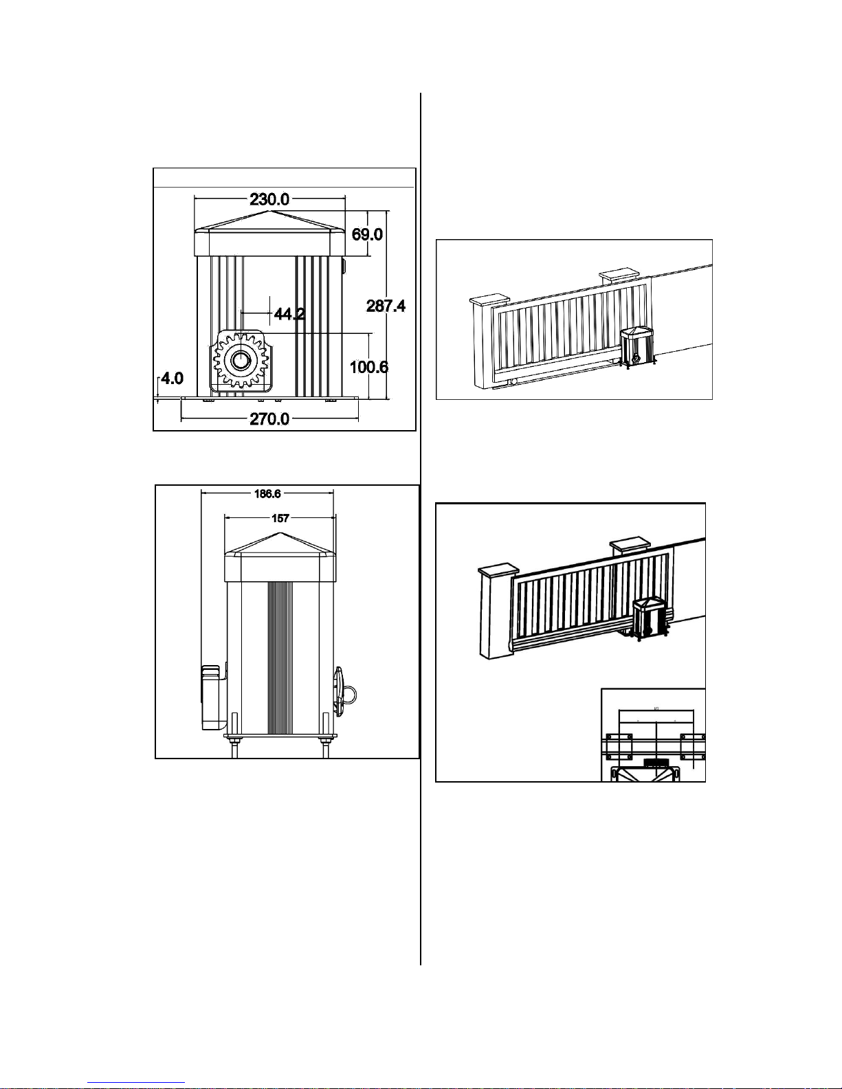
1.2 Dimension
1-2-1
1-2-2
1.3 Gate variations
The standard supply package is suitable
for the following types of gates.
Gate system on rails
1-3-1
Cantilevered gate system
1-3-2
Page 6
6
2.1 General notes
The picture in these instruction are not
true-to-scale.
All the dimensions are shown in
millimeters(mm)!
The motor can be mounted on the right
or left hand side of the gate depending
on the direction of opening.
These instructions show the motor being
installed on the right hand side.
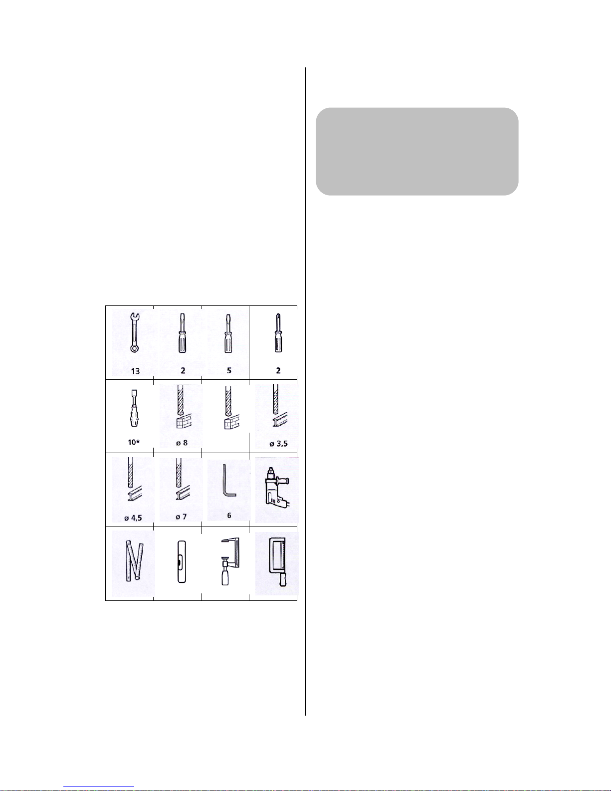
For correct mounting you will need the
following tools:
2-1-1
* Minimum shaft length is 160mm.
2.2 Checks
Supply contents :
Check the package to ensure that all
the parts are included.
Check that you have all the
additional components that are
necessary for your particular
installation requirements.
Foundations
Check the proposed installation
location for the operator system:
— The motor unit and the toothed
rack must be installed on the
inside of the gate with the gate
closed.
— The motor unit should not be
installed within the clear width!
— For cantilevered gates, the motor
unit must be mounted at the mid
point between the carrier roller
assemblies.
— The foundations must be suitable
for heavy duty wall plugs.
Check whether the existing
foundations are suitable.
Check the supply cable.
Pay particular attention to the cable
exit point where the motor unit is to
be installed.
Attention!
In order to guarantee correct
mounting,carry out the following
checks before installation.
Φ12
Page 7

7
Gate system
Ensure that your gate system has an
appropriate electricity supply
connection and a facility for
disconnecting the mains. The
minimum cross-sectional area of the
earth cable is 3×1.5mm2
Ensure that all cables are suitable
for outdoor use(cold resistant and
UV resistant).
Check that the gate to be operated
fulfils the following conditions:
— The travel path of the gate must
be horizontal.
— When closed, the gate should
exceed at least 400mm further
than the height on the same
installation side.
— The gate must have a mechanical
gate stop for both direction.
— The closing edges must be fitted
with a flexible gate seal.
— The gate itself must be straight,
so that the distance between
motor unit and the gate never
changes.
Page 8
8
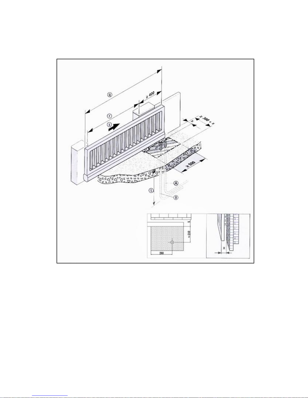
2.3 Gate and foundation layout
2-3-1
A Empty conduit for control cable
B Empty conduit for electricity supply cable
q Gate width
r Clear width
s Opening direction
t Below depth of frost penetration
x Gate thickness+ distance from structure
Page 9
9
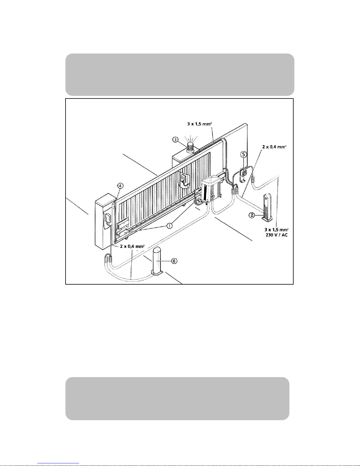
2.4 Cabling layout
2-4-1
1、Signal transmission system
2、Infrared beam
3、Caution light
4 、 Closing edge safety device
(SKS)
5 、 Mains isolater switch(mains
disconnection facility)
Reference:
For the installation and cabling of the gate sensors, control elements and
safety equipment ,the relevant installation instructions must be observed.
Advice:
This is just an example of a cabling layout,the layout can vary according to the
type of gate and the associated equipment.
Page 10

10
3.1 Installing the motor unit
3-1-1
3-1-2
Open the motor unit cover.
3-1-3
A Wall
B Gate
C Mounting surface for the
toothed rack
D Output shaft of the motor unit
E Front edge of the toothed rack
F Floor console
G Clear width
H Cable entry for power
supply/control cable
I Foundation
Attention!
To install the motor unit correctly,
it must be mounted at the mid
point between the carrier roller
assemblies if the gates are
cantilevered.
Attention!
To install the motor unit
correctly,the following points
must be assured:
—The spur gear must accurately
mesh with the toothed rack.
— The wall plugs for the floor
console must be at least 80mm
from the edge of the foundation.
Page 11

11
Before installing the motor unit,
check whether the possible height
adjustment of the motor unit is
sufficient for the situation on site,or
if the motor unit needs to be raised
on a backplate.
Align the floor console ,with the
motor unit parallel to the gate.
Drill the holes for the wall plugs as
shown in the drilling diagram.
3-1-4
Push in the wall plugs
Feed the control cable and the
power supply cable through the
floor console.
Adjust the motor unit
Screw the floor console into place
Caution!
Danger of electric shock:
Before commencing cabling
works it is very important to
disconnect the operator system
from the electricity supply.
Ensure that the electricity
supply remains disconnected for
the duration of the cabling works.
Reference:
The height adjustment of the
motor unit is described in section
3.3.
Notes:
When using an existing toothed
rack, the correct dimension is
27mm from the first screw to the
front edge of the toothed rack.
Reference:
When determining the mounting
surface for the toothed rack, the
information given in section 3.2.2
must be observed.
Page 12

12
3.2 Mounting the toothed
rack
3.2.1 General
Toothed rack are available in several
standard lengths and some fixing rack
accessories.
The toothed rack is made up of several
toothed rack segments.
Minimum length of toothed rack
Minimum length of toothed rack is equal
to the movement stroke of the gate
between the gate OPEN and CLOSED
positions+180mm
Maximum length of toothed rack
Maximum length of toothed rack is
equal to the width of gate.
3.2.2 Determining the
installation height
3-2-1
Determine the installation height of
the toothed rack on the gate
Adjust the height of the spur gear
accordingly.
Notes:
The toothed rack can be adapted to
fit the gate by means of backplate(D).
Reference:
Section 3.3 describes the height
adjustment for the motor unit.
Attention!
gate,the following points must be assured:
operation of the gate.(e.g. by extending into
the path of the gate rollers(B).)
the gate.
low to avoid mesh apart with the rack.
point that meshed)
Reference:
— For gates with an existing
toothed rack,please skip to
Section 3.3.
— Section3.5 describes how to
release the motor unit.
Attention!
To install the rack
correctly,the following
must be ensured:
— The motor unit has been
mounted.
— The motor unit is released.
Page 13

13
3.2.3 Determining the length
and installation position of
the toothed rack
Maximum length of toothed rack
If a toothed rack is to be installed across
the entire width of the gate ,then the
installation position does not have to be
determined.
The length and installation position of
the toothed rack correspond to the gate
width.
Minimum length of toothed rack
The minimum length of toothed rack
must be determined at the gate.
3-2-2
Move the gate to the CLOSED
position.
Make a mark on the gate:
90mm from the centre of the spur
gear in the direction of opening.
3-2-3
Move the gate to the OPEN
position.
Make a mark on the gate:
90mm from the centre of the spur
gear in the direction of closing.
3-2-4
Attention!
To ensure trouble-free operation,
the toothed rack must at least extend
across the area(E) between the
markings.
Page 14

14
3.2.4 Adjust the length of
the toothed rack
Measure the required length of the
toothed rack at the gate.
Change the standard length to required
length of the toothed rack:
The toothed rack need not to be
adjusted.
When the standard rack length is
longer than the required length:
3-2-5
When the standard rack length is
shorter than the required length.
3-2-6
Place the required number of the
toothed rack end to end.
Cut off any excess length from the
last toothed rack using a metal
saw.
Cut off the excess length of the toothed
rack using a metal saw.
Attention!
To avoid damaging the
toothed rack segments , there
should be no toothed rack
segments in the rack housing at
the point where the cut is to be
made.
Page 15

15
3.2.5 Mounting the toothed
rack
Fixing nuts need to be welded on
different position of the gate before
installing the toothed rack.
3-2-7
3-2-8
Hold the toothed rack in place
according to the fixing rack nuts
welded on the gate on the spur
gear side.
Place the toothed rack onto the
spur gear so that the toothed rack
engages the spur gear.
Adjust the toothed rack
horizontally.
Using a spanner to hold the
toothed rack in position of the
fixing rack nuts.
3-2-9
According to the above-mentioned
process, place other racks with the
bolts to the fixing rack nuts.
Attention!
To ensure correct operation, the
toothed rack must always be pushed
onto the spur gear as the gate is
moved.
Reference:
The reference point magnet
must be installed before the rack is
mounted. Section 3.4 describes
how to install the reference point
magnet.
Attention!
To ensure the gate can move
smoothly, the countersunk screw
must be tightened and adjusted
accordingly.When welding the
fixing rack nuts, make sure to
weld the smaller end to the gate
barrier, and the bigger end face to
the toothed rack. All the surface
of bigger ends must flush with
each other.
Page 16

16
3-2-10
Push the gate one cycle in the
direction of closing by hand, and
adjust the clearance between the
rack and spur gear.
Tighten all the nuts after adjusting
the height.
3.2.6 Adjust the motor unit
3-2-11
The height of the motor unit must be
re-adjusted now.
Lower the spur gear by 1 to 2mm
Check:
To check that the spur gear
engages the toothed rack along its
entire length,the gate must be
pushed once to the OPEN position
and back to the CLOSED position.
Reference:
Section 3.3 describes how to adjust
the height of the motor unit.
Attention!
To ensure the gate runs smoothly,
it is important that a vertical gap of 1
to 2mm is maintained between the
toothed rack and the spur gear.
Page 17

17
3.3 Adjusting the height of
the motor unit
3-3-1
3-3-2
According to the Fig.3-1-4,tighten
the bottom screw A after fixing the
wall plug.
Adjust the Nut(B) in the middle of
the wall plug until the motor is in
suitable position.
Tighten screw(C) at the top after
fixing the flat washer and spring
washer.
3.4 Mounting the reference
point magnet
The operator system determines the
gate positions and the extent of travel
electronically. So it requires a
reference point on the gate or on the
toothed rack.
Using a special reference point magnet
as the reference point.
3-4-1
Drive the door to the CLOSED
position
Attention!
To ensure correct operation, any
existing magnets must be
removed.(e.g.in the case of retrofit
measures with an existing toothed
rack).
Caution!
To avoid injury ,the gate must have
a mechanical end stop in both
directions; otherwise it could spring
out of line.
Page 18

18
Determin the position for the
reference point magnet.
3-4-2
The mounting of the reference point
magnet is dependent on the type of
toothed rack that is used.
3
3-4-4
3-4-5
Mount the reference point magnet
in the magnet housing.
Mount the cover onto the magnet
housing.
Mount the magnet housing at the
previously determined position on
the toothed rack.
Check the position of the reference
point magnet.
Check the distance between the
reference point magnet and the
motor unit.
Check the distance between the
centre of the reference point
magnet and the internal hall height
of the motor unit.
Attention!
To avoid faults occuring, the
following dimensions must be
adhered to without fail:
— The distance between the
reference point magnet(A) and the
motor unit(B) must be 2 to 8mm.
—The distance between the centre of
the magnet(A) and the centre of the
spur gear(C) must be 70mm.
Page 19

19
3.5 Release
3-5-1
Place the release key into the
keyhole at the bottom of the motor unit.
3-5-2
Hold the triangle plastic part
outside the lock, turn clockwise by
180·until it stops.
Move the door shortly by hand in
the OPEN and CLOSE direction.
The transmission is now mechanically
disengaged from the drive shaft. The
gate can only be moved manually. The
electric circuit in the controls is
interrupted and the controls are out of
operation.
3.6 Locking
3-5-3
Hold the triangle plastic part outside
the lock, turn anti-clockwise by
180·until it stops. Push the door
front and back by hand
to ensure the gear is engaged.
3-5-4
Pull the key out of the keyhole at
the bottom of the motor unit.
The transmission and drive shaft are
now mechanically engaged. The gate
can be driven via the motor. The
electric circuit in the controls are in
operation.
Page 20

20
3.7 Restore the limit setting after power restoration
When the power restoration, Please use the transmitter or wall switch to open and
close the door for one cycle, then the initial set travel limit will be recovered
automatically. If not, the door opening/closing position will be error.
Attention!
Do not rotate the key !
When re-engage after releasing,
limit movement may happen. Please
use the transmitter or wall switch to
open and close the door for one cycle,
then the initial set travel limit will be
recovered automatically.
Page 21

21
4.1 Connection of Mains
cable
4-1-1
Open the cover of the motor unit,
loosen the two fixing screws on the
junction box at the wall side of the
motor,and open the cover.
4-1-2
Put the mains cable with protector
jacket through the hole at the bottom of
the motor unit.
Loosen the screws on the terminal
block, then connect the two peeled
end(L、 N) to the terminals on the
terminal block, tightened the screws.
Connect the ground wire to the earth
terminal of the motor, make sure it is
tight.
Fix the mains cable together with
the motor wire using cable ties.
Close the cover of the junction box,
and then tighten the screws.
4-1-3
Fix the cable plugged into the
motor to the hole like the drawing.
Attention:
The sliding gate operator
should use:
---AC220V (or
AC240V/AC110V) power
supply.
---To be installed by
professional technicians, and to
use the cables fit safety standard
3 × 0.75mm ².
Page 22

22
4.2 Connection of control elements
4-2-1
4.2.1Wireless closing edge safety device connection
The connection is suitable for the wireless safety device with DC24V and NC
type. Section 4-2-1 describes how to connect the wireless safety device .
Attention!
Please shorten the two terminals “COM” and “SAFE” by wire conductor if this
function is not required, or the motor will not be able to close the gate.
Opening edge safety
device(opening direction)
Wireless
protector
receiver
Infrared beam
O/S/C button
Caution light
Battery backup
Closing edge safety
device(closing
Page 23

23
4.2.2 Infrared beam connection
Section 4-2-1 describes the
connection of “Infrared beam”
Activate the infrared beam(H1 or
H2) by the setting interface
“P4”.Press „SET‟ button and hold
on until the LED displays figure
„P4‟,then press ”SET” once to
confirm, the LED will
displays”H1or H2”,then the
function is available.
When the self-checking function of
infrared beam(H2) is activated, the
motor will not work if the protector
is failure, the LED will display “r”.
If the connection is OK, the lamp
“PE” will normally on during
closing cycle,will off when it is
obstructed.
4.2.3 Opening edge and closing
edge safety device connection
This is suitable for pressing to
short-connected safety device.
Connect an 8.2 kΩ resistor to the far end
of the closing edge safety device.
Section 4-2-1 describes the
connection of “closing edge safety
device-closing direction” and
“closing edge safety device-opening
direction”
Attention:
When the safety device is not used,
an 8.2 kΩ resistor is required to be
installed at the relevant terminals.
When the resistance of the safety
device is far below 8.2 kΩ,(corresponds
to the shor-connecting of the safety
device),or the resistance is much higher
than 8.2 kΩ,(equals to the open circuit
of safety device), the relevant CEP light
will normally on, and the motor will not
work.
Attention:
If the infrared beam is not used,
please disable the function, as the
same setting “P4→ HO”, or the
gate can not be closed by the
motor.(Please according to section
4.3)
Attention!
To correctly operation, we
strongly advise to use infrared
beam with three-wire,on-off
controlled, DC24V, the control
contact points is NC style.
Page 24

24
4.2.4 "O/S/C" button
connection
Section 4-2-1 describes the
connection of “O/S/C button”.
4.2.5 Caution light
connection
Section 4-2-1 described the
connection of caution light.
The caution light will go on during
opening and closing,will go out when
stopped.
The output voltage is DC24V, and
the maximum current is :800mA.
Please choose the caution light
DC24V , ≤ 20W, and use the 2 ×
0.5mm
2
wire to connect
4.2.6 Battery backup
connection
The section 4-2-1 described the
connection of the battery backup.
Use the battery 24V, ≥ 3.6AH,the
wire cross-sectional area ≥
0.75mm2 × 2.
Please note“+, -” polarity, and fix by
the professional electrician.
4.2.7 Pedestrian mode
Set according to section4.3, when
the LED displays”0”,this function is
invalid. When the LED displays “1”, the
door will be opened to the 30cm position.
When it displays”2”,the door will be
opened to the 60cm position, and so
forth. When the LED displays ”9”,the
door will be approximately opened to
the 270cm position.
Attention:
Please choose the one-touch
switch.
Use the 2 × 0.4mm
2
plastic-covered cable to connect.
Page 25

25
4.3 Setting the function
Page 26

26
4.4 Hand transmitter coding
Press and hold „CODE‟ button over than 8 seconds, the LED dot lights up. And
then press “O/S/C” button on the transmitter, the LED goes out. Press “O/S/C” button
once again ,the LED fast flashed 8 times. The transmitter coding finished.
Auto reverse:
The gate will stop when obstacle during the opening.
The gate will reverse when obstacle during the closing.
Attention:
Press and hold “CODE”button until the LED dot lights up,all the transmitters
codes held in the memory will be erased.
This operator can learn at least 20 transmitters.
Page 27

27
5.1 Technical feature of sliding gate operator
Model
500KG
800KG
Model
500KG
800KG
Input
voltage
AC220~240V
AC220~240V
Caution light
connector
one group
one group
Working
voltage
DC24V
DC24V
Opening
edge safety
device
connector
one group
one group
Rated
Power
150W
180W
Closing edge
safety device
connector
one group
one group
Rated pull
force
210N
260N
Wireless
security
switch
connector
one group
one group
Rated
torque
7NM
10NM
Infrared
beam
connector
one group
one group
Max travel
speed
10M/MIN
10M/MIN
O/S/C
connector
one group
one group
Max
Opening
width
10M
10M
Auto reverse
YES
YES
Automatic
closing time
120S
120S
Soft start
YES
YES
Transmitter
frequency
433.92Hz
433.92 Hz
Soft stop
YES
YES
Page 28

28
6.1 FAQ
Error
Possible causes
Advised solution
No reaction on the operator.
1、 Power failure.
2、 Connecting wire loosen
between transformer
and main board.
※ 1 、 Check plug and power
supply.
※2、Loosen the four screws of
the control box on the
cover, re-fit the referent
plug.
Motor does not work, there is
“da da” sound inside the
motor, as well as the LED
displays“— —”.
The clutch is in the
disengaging state.
Engage the clutch.
Motor does not work, there is
no sound inside the motor, and
the LED displays“— —”.
Opening and closing limit
has not been set.
Reset the travel limit according to
the instruction.
Only opening allowed,and the
LED shows “— —”or ”r”.
The infrared beam function
is activated, but has not been
connected.
Enter the setting interface (P4→
HO), and close the function.(we
suggest to use the infrared beam)
Only opening allowed, and the
CDP light is off.
Has not connected the
wireless protector, and the
relevant terminal has not
been short circuited,or short
wires is loosen.
Installed the wireless protector or
shorten the two terminals “COM”
and “SAFE”.And now the CDP
light will be on.
Can not opened or closed,the
CEP or the OEP light is on .
1、 Did not connect the 8.2
kΩ reference resistor
when fixing the safety
device.
2、 The 8.2 kΩ reference
resistor loosen when the
safety device not
connected.
3、 Faulty wiring in safety
device.
1、 As required, connect an 8.2
kΩ reference resistor to the
far end of the safety device.
2、 Re-connect the 8.2 kΩ
reference resistor.
3、 Get rid of any open or shorted
faults of the safety device.
After setting the travel limit, in
the process of auto-learn ,the
motor stopped automatically,
as well as the LED shows “E”.
Has not installed the
reference point magnet or
the installation position is
out of place.
Re-install the reference point
magnet as required and ensure
that when the motor passed
through the reference point
magnet, the signal light will be
on.
Page 29

29
The motor exceed the travel
limit and not stop.
Reference point magnet
come off or dislocated.
Re-install the reference point
magnet as required and re-set the
travel limit.
Opening and closing turn
upside down.
The setting of the right hand
or left hand installation is
wrong.
Press the “SET” button until the
LED shows “P6”. And then
change the right hand and left
hand installation. Right hand
installation is “Lt”, right hand
installation is “rt” .
The gate can not be fully
closed but reversed 20cm.
Some obstacle in the gate.
1、 Remove the obstacle and try
again.
2、 Re-set the travel limit.
3、 Increase the auto-reverse
force.
Automatically stop during
opening.
Some obstacle in the gate
and the motor auto stop.
1、 Remove the obstacle and try
again.
2、 Re-set the travel limit.
3、 Increase the auto-reverse
force.
The motor stops automatically
after running few centimeters
in both opening and closing
cycle, the LED shows “H”.
1、 Hall sensor wires
loosen.
2、 Hall sensor damaged.
3、 Failure on circuit board.
※1、Re-plug Hall sensor wires.
※2、Check or replace Hall sensor
wires.
※ 3 、 Replace control circuit
board .
The hand transmitter is out of
use or has short remote control
distance.
1、 Battery has run out.
2、 Aerial goes off or has
not been stretched properly.
3、 Any radio interference
nearby.
1、 Replace battery.
2、 Check and stretch aerial.
3、 Eliminate source of
disturbance.
Hand transmitter can‟t be
learnt.
1、 Full memory in the
transmitter(The motor
can be learnt by 20
transmitters).
2、 The transmitter which
you used is not the one
supplied with the motor.
1、 Erase all memories and
re-coding ( Press “CODE”
button until the LED shows
“dL”).
2、 Use the transmitter we
supplied.
When re-engage after
releasing, limit movement
happened.
After re-engaging ,the
beginning of travel is not
synchronous.
Use the transmitter or wall
switch to open and close the
door for one cycle,then the
initial set travel limit will be
recovered automatically.
Page 30

30
The power restoration after
power failure , the limit
movement happened.
when power restoration,
the motor can not
distinguish the current
position.
Plesae make sure the clutch
is engaged . then use the
transmitter or wall switch to
open and close the door for
one cycle,then the initial set
travel limit will be recovered
automatically.
Note:
The Asterisk(※)solution should be finished by professional technician.
 Loading...