

Shark 250 Quick Start Manual
Electro Industries/GaugeTech
The Leader In Power Monitoring and Smart Grid Solutions
Electro Industries/GaugeTech
The Leader In Power Monitoring and Smart Grid Solutions
Shark® 250 Meter Quickstart Guide
DIN mounting
bracket
Top mounting
bracket groove
Bottom
mounting
DIN Mounting brackets
Remove (unscrew) ANSI studs
for DIN installation
DIN Installation
92mm Square
form
ANSI Installation
ANSI Studs
4.0” Round form
lc
HI
LO
lb
HI
LO
la
HI
LO
Earth Ground
L(+)
Power
Supply
Connection
N(-)
L(+)
GND
N(-)
Vref
Va
Vb
Vc
LINE
LOAD
CT
Shorting
Block
FUSES
3 x 0.1A
FUSE
3A
C
C
B
B
A
A
N
N
lc
HI
LO
lb
HI
LO
la
HI
LO
Earth Ground
Earth Ground
L(+)
Power
Supply
Connection
N(-)
L(+)
GND
N(-)
Vref
Va
Vb
Vc
LINE
LOAD
CT
Shorting
Block
FUSES
3 x 0.1A
FUSE
3A
C
C
B
B
A
A
N
N
lc
HI
LO
lb
HI
LO
la
HI
LO
Earth Ground
Earth Ground
L(+)
Power
Supply
Connection
N(-)
L(+)
GND
N(-)
Vref
Va
Vb
Vc
LINE
LOAD
CT
Shorting
Block
FUSES
2 x 0.1A
FUSE
3A
C
C
B
B
A
A
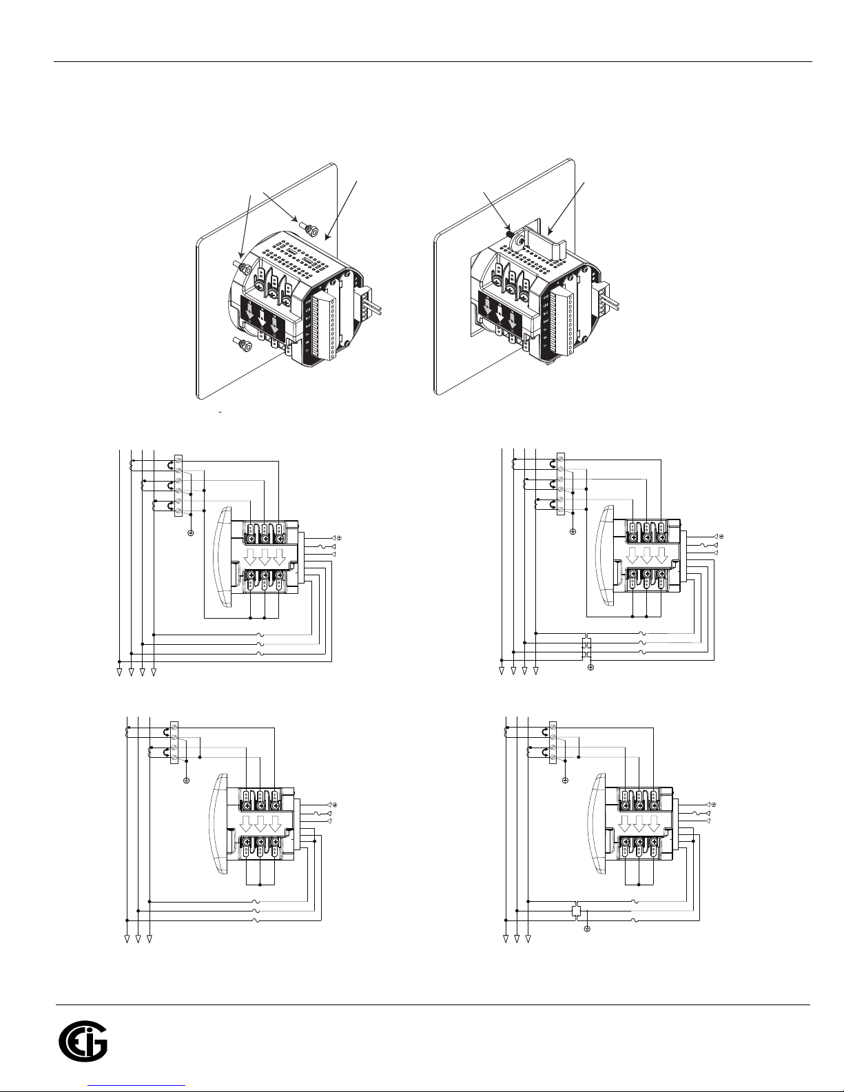
WYE direct, 3
phase, 4 wire
Delta direct, 3
phase, 3 wire
lc
HI
LO
lb
HI
LO
la
HI
LO
Earth Ground
L(+)
Power
Supply
Connection
N(-)
L(+)
GND
N(-)
Vref
Va
Vb
Vc
LINE
LOAD
CT
Shorting
Block
FUSES
3 x 0.1A
FUSE
3A
C
C
B
B
A
A
Mechanical Installation:
Electrical Installation: Select diagram for your application.
NOTE: Do not overtighten nuts. The maximum installation torque is 0.4 Newton-Meter.
Shark® 250 Meter Quickstart
NOTE: Other wiring configurations are available. See the full User Manual on the enclosed CD.
WYE with PTs,
3 phase, 4 wire
Delta with PTs, 3
phase, 3 wire
Doc# E169703 V.1.02 QS - 1
Shark® 250 Meter Quickstart
Electro Industries/GaugeTech
The Leader In Power Monitoring and Smart Grid Solutions
Electro Industries/GaugeTech
The Leader In Power Monitoring and Smart Grid Solutions
A
B
C
-
-
-
MENU ENTER
A
B
C
-
-
-
MENU ENTER
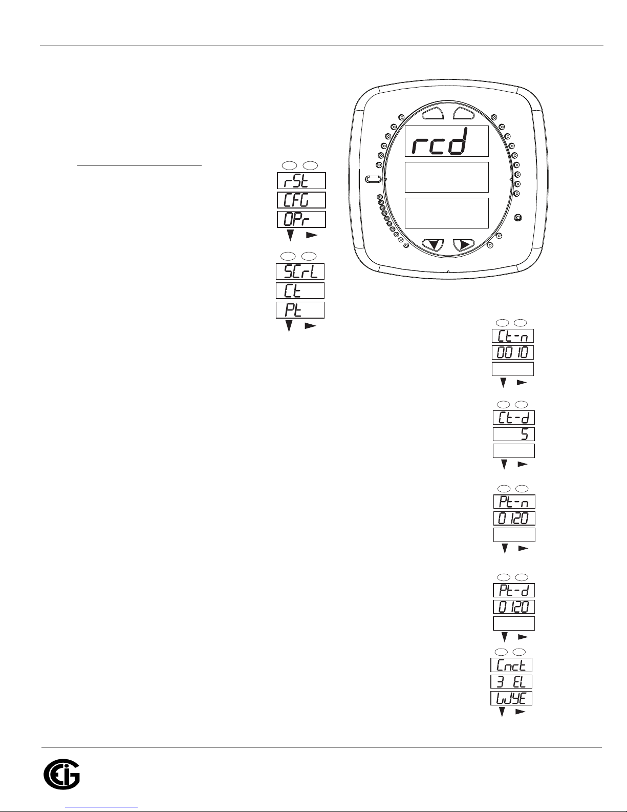
Program Settings Using the Faceplate Buttons:
(MENU, ENTER, DOWN ARROW, RIGHT ARROW)
See the figure on the right for the location of the
faceplate buttons.
Access Configuration Mode
1.Push the MENU button - you will see
the display on the right; rSt will be
blinking.
:
MENU ENTER
-
-
-
2.Press the DOWN ARROW once.
A
B
C
%THD
PRG
120%-
90%-
LM2
lrDA
LM1
60%-
MAX
MIN
-
-
-
30%-
CFG (Configuration) moves to the
top of the display.
3.Press the ENTER button. You will
see the Configuration menu, shown
on the right.
4.Press the DOWN ARROW and then
press the ENTER button. You will see the CT numerator setting screen (Ct-n).
The current CT numerator is shown in the second line. To change the setting,
press the DOWN ARROW until the value you want is displayed. Then press the
RIGHT ARROW to move to the next digit. Repeat until the setting is done.
5.Press the ENTER button to go to the CT denominator screen (CT-d). This setting is
display only - it can’t be changed.
Example: 2,000/5 Amps: Set the Ct-n value for 2000.
NOTE: Ct-n is dictated by primary current; Ct-d is secondary current.
6.Press the ENTER button to go to the PT numerator setting screen (Pt-n).The current
PT numerator is shown in the second line. To change the setting, press the DOWN
ARROW until the value you want is displayed. Then press the RIGHT ARROW to
move to the next digit. Repeat until the setting is done.
7.Press the ENTER button to go to the PT-denominator screen (Pt-d). The current
PT denominator is shown in the second line. To change the setting, press the DOWN
ARROW until the value you want is displayed. Then press the RIGHT ARROW to
move to the next digit. Repeat until the setting is done.
Example: 277/277 Volts: Pt-n value is 277, Pt-d value is 277.
NOTE: Pt-n is dictated by primary voltage; Pt-d is secondary voltage.
8.Press the ENTER button to go to the Connection setting screen (Cnct). The current
setting is shown in the second line. Press the DOWN ARROW to choose another
value. You can choose 3 EL (element) WYE, 2 Ct del (Delta), or 2.5 EL WYE.
MENU ENTER
0000
0.659
%LOAD
A
B
C
-
-
-
-
-
-
-
-
-
-
-
-
VOLTS L-N
VOLTS L-L
AMPS
W/VAR/PF
VA/ Hz
Wh
VAR h
VAh
Wh Pulse
KILO
MEGA
MENU ENTER
A
B
C
MENU ENTER
A
B
C
MENU ENTER
A
B
C
MENU ENTER
A
B
C
Doc# E169703 V.1.02 QS - 2
Shark® 250 Meter Quickstart
Electro Industries/GaugeTech
The Leader In Power Monitoring and Smart Grid Solutions
Electro Industries/GaugeTech
The Leader In Power Monitoring and Smart Grid Solutions
0000
-
-
-
A
B
C
MENU ENTER
-
MAX
MIN
LM1
LM2
%THD
VOLTS L-N
VOLTS L-L
AMPS
W/VAR/PF
VA/Hz
Wh
VARh
VAh
120%-
90%-
60%-
30%-
%LOAD
MEGA
KILO
Wh Pulse
PRG
A
B
C
-
-
-
MENU ENTER
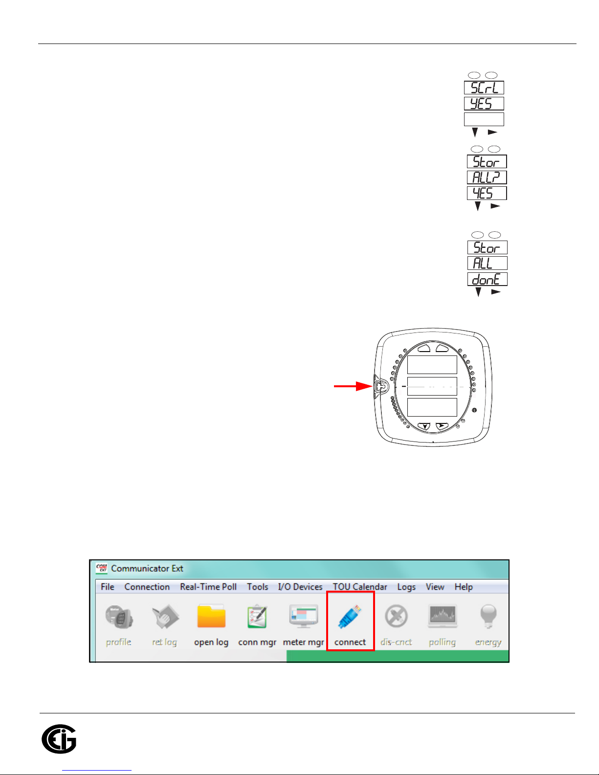
9. Press the ENTER button to go to the Scroll setting screen (SCrL). The current
setting is shown in the second line. Press the DOWN ARROW to choose another
setting. You can choose YES (the meter readings will scroll on the display) or no
(the meter readings will not scroll on the display).
10.Press the MENU button twice. You will see the Store Settings screen (Stor ALL?)
The default setting is YES. To save the settings you’ve made, press the ENTER
button. You will see the confirmation screen (Stor ALL done) and then the meter
resets.
NOTE: If you do not want to save your settings, press the RIGHT ARROW. YES
changes to no. Press the ENTER button.
For additional programming instructions for the faceplate buttons, see Chapter 2
in the Shark® 250/250T Meter Installation and Operation Manual, on the enclosed
CD and on EIG’s website: www.electroind.com.
Connect to the Meter through the USB Port:
The Shark® 250 meter has a standard USB port that
makes connection between the meter and a laptop PC
very simple.
Follow these steps:
1. Connect the meter to the PC, using the USB cable.
The meter’s connection uses a USB mini-B plug. For
your convenience, EIG offers a USB-Type A plug to
USB mini-B plug cable (part number E169305) that
can be ordered directly from EIG’s webstore: https://electroind.com/shop/.
-
-
-
-
-
-
MENU ENTER
A
B
C
MENU ENTER
A
B
C
2. Open Communicator EXT
product CD).
3. Click Connect in the Icon Bar.
4. You will see the Connect screen. The default settings are shown in the following example screen.
TM
software (download from
Doc# E169703 V.1.02 QS - 3
 Loading...