

Page 1
REPLACEMENT PARTS
MODEL S3000 & S3000e (47” x 70” Floor)
Part# Description
3000.1 Fabric Tent
3000.2 Frame Assembly
3000.4 Floor Pole (only)
3000.5 Roof Tube (plain end)
3000.6 Roof Tube (formed end)
3000.7 Elastic Frame Cord
3000.8 Carpeting (S3000)
10446 9” x 16” Window/Shade
Accessories
IA2 Ice Anchor
SK3000 Ski System
To Order Parts, give Part No., Description and Qty Needed.
SHAPPELL CORP., 3562 W. Jefferson Hwy., Grand Ledge, MI 48837
Toll Free (888) 571-1144
CONSUMER WARRANTY
SHAPPELL CORPORATION warrants its products against defects in material
and workmanship for (1) YEAR from date of purchase. We will provide FREE
repair or replacement, in whole or in part, at our option, for any product, found
in our opinion to be defective. If return is required, freight must be prepaid.
This warranty does not cover Freight Damage, Ordinary Wear and Tear, Abuse,
Misuse or Altered Product.
3000.5
3000.6
3000.1
3000.2
3000.4
3000.8
(S3000)
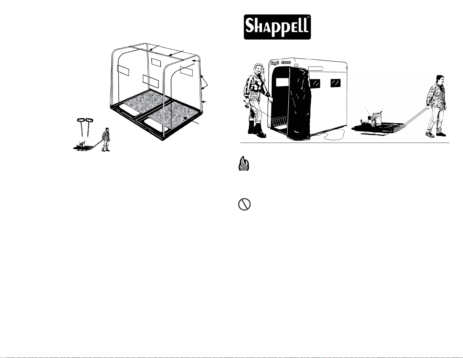
Model S3000/S3000e
PORTABLE ICE FISHING SHELTER
Shown with Optional
Ski System.
IMPORTANT SAFETY INFORMATION
WARNING: Keep all Heat & Flame Sources away from the Shelter’s Fabric
Cover. The Fabric Cover is Fire Retardant, it is not Fire Proof. The use of any
heat source can be extremely dangerous, both for Fire Hazard and Carbon
Monoxide Emissions. The Shappell Corporation does not endorse the use of any
Heater. It is the user’s responsibility to follow the Instructions and Warnings
provided by the Heater Manufacturer for the safe use of a particular Heater.
O
C
CARBON MONOXIDE POISONING HAZARD: This shelter is nearly air tight
and must be ventilated if using an oxygen consuming heat source. An extra zipper
pull at the top of each door provides ventilation and can also be used to form a
window for viewing. DO NOT PACK SNOW AROUND SHELTER or in any
way prevent fresh air from entering shelter. Failure to Ventilate Shelter could
create a Serious Health Hazard or Death.
Towing of shelter with a motorized vehicle is not recommended.
Window can not be made to withstand temperatures below –15oF. (see warranty)
WINDOWS ARE NOT GUARANTEED AT TEMPERATURES BELOW
–15 DEGREES FAHRENHEIT.
For warranty claim, send letter indicating product and explanation of defect plus
dated proof of purchase to the SHAPPELL Corp., 3562 W. Jefferson Hwy,
Grand Ledge, MI 48837.
Revised 6-08
Page 4
PREVENT DAMAGE TO HINGE JOINT: Always set shelter on a level flat
surface.
MAINTENANCE: After each use, set up shelter until fabric is completely dry.
Never leave shelter folded closed with a wet cover.
NOTICE: It is normal for fabric to have some pinholes. This does not affect
water repellency.
READ SETUP & TAKEDOWN INSTRUCTIONS BEFORE USING SHELTER
Page 1 (10077)
Page 2
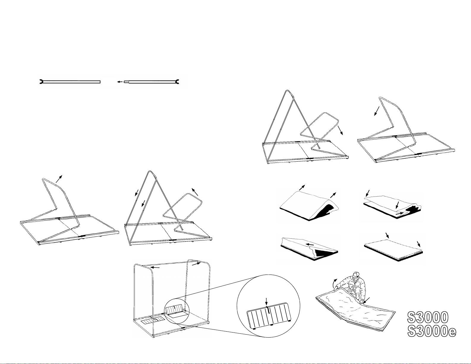
SET UP INSTRUCTIONS
TAKE DOWN INSTRUCTIONS
1) Open floor on a flat, level surface, with a door end facing
the wind. Damage to Hinge Joint may occur if Floor is not
evenly supported.
2) Assemble Roof Tube sections.
3) Fig. 1, Raise one U Shaped Frame. Keep Frame about 24”
away from Corners of Fabric Top and Slip ends of U Frame
over Crimped ends of Floor Poles...Shock Cord will pull Frame
together. Push Assembled Frame into Corners of Fabric Top
and adjust Seam in Fabric so that it follows the Curve of the
Frame. Snap end of Roof Tube Assembly to Center of U
Frame and Support Frame as shown in Fig. 2.
Fig. 2
Fig. 1
1) Fig. 4, Remove Roof Tube from Center of one U Frame
and use Roof Tube to Support other U Frame as shown.
Pull U Frame away from Fabric Corners, then pull apart and
Fold Frame to Floor while keeping Fabric away from Frame.
Do Not Wrap Fabric Around Frame. NOTE: U Frame
should lay inside of the Floor Poles, not on top of them. Repeat for other U Frame, Fig 5.
Fig. 4
Fig. 5
2) Fold Tent as shown in Fig. 6,7,8,9 and 10
Fig. 6
Fig. 7
4) Fig. 2 & 3, Raise second U
Frame, again keeping Frame
about 24” away from Corners of
Fabric Top. Assemble Frame
and push into Corners of Fabric
Top and adjust Seam in Fabric
to follow Curve of the Frame.
Clip end of Roof Tube Assembly
to Center of U Frame.
Page 2
Fig. 3
Fig. 8
Pull shock cordinto
slot in fish door to
hold door open.
Fig. 10
Page 3
Fig. 9
Hold Down Frame
6-08
 Loading...