

Owner’s Manual
Interface Unit
Model N. ISEEI
Please read this instruction carefully before using this product,
and save this manual for future use.
If you have any questions, visit www.shapewlb.comm call Free 1.888.968.9810 or 1.450.812.4712

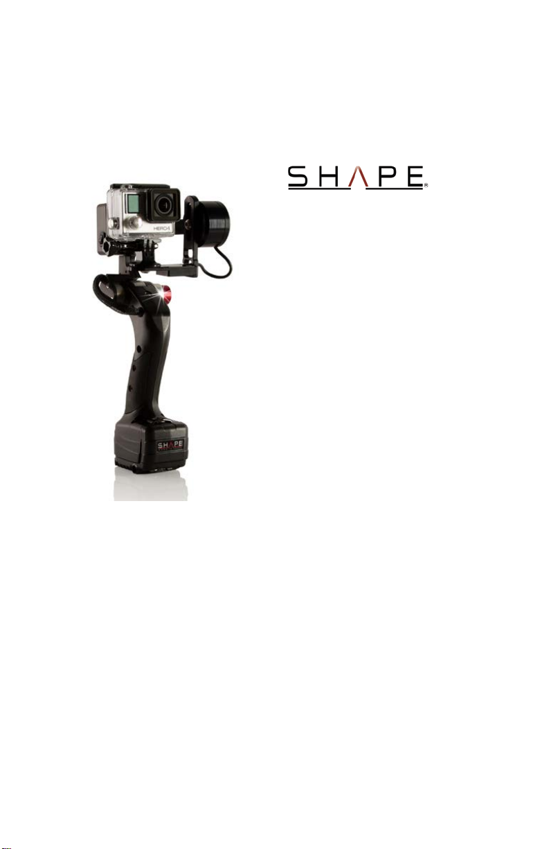
THANK YOU FOR PURCHASING THE SHAPE® ISEEI GIMBAL
MOTORIZED GIMBAL STABILIZER GOPRO –SMARTPHONES
® introduces a new li ne of products, the ISEE series. The
SHAPE
camera is balanced on a two axis gimbal and is stabilized on the
tilt axis and on the roll axis using motors and sensors.
The stabilizing device is equipped with a joystick to manually
control the camera movement and is powered by 2x LP-E6
rechargeable batteries.
COPYRIGHT
© SHAPE wlb Inc. 2014
All Rights Reserved
2

CONTENTS
Read this first! ...............................................................................4
Handling the unit………………………………………………………6
What’s in the box………................................................................8
Components................................................................................10
Technical Specifications..............................................................12
Before using the Gimbal..............................................................14
Using the Gimbal with a Smartphone……………………….……..16
Warranty......................................................................................17
Contact Us...................................................................................18
Notes…………………………………………………….……………19
3
READ THIS FIRST!
WARNING:
To reduce the risk of fire, keep this equipment away from all
liquids. Use and store only in locations which are not exposed to
the risk of dripping liquids, and do not plac e any liquid containers
on top of the equipment.
WARNING:
Always keep equipment out of reach of babies and small children.
WARNING:
This unit is splash/rain resistant.
NOT suitable for showering, swimming, snorkelling, water related
work.
CAUTION:
Do not remove panel covers by unscrewing.
Refer servicing to qualified service personnel.
CAUTION:
To reduce the risk of fire and interference, only use the
recommended accessories.
CAUTION:
The high temperature parts of the device that are in direc t c ontact
with the skin may aggravate low temperature burn injuries.
4

READ THIS FIRST! (continued)
FCC NOTICE (USA)
This device complies with part 15 of the F CC Rules. Operation is
subject to the following two conditions: (1) This devic e may not
cause harmful interference, and (2) this device must accept any
interference received, including interference that may cause
undesired operation.
CAUTION:
This equipment has been tested and found to comply with the
limits for a Class B digital device, pursuant to part 15 of the FCC
Rules. These limits are designed to provide reasonable protecti on
against harmful interference in a residential installation. This
equipment generates uses and can radiate radio frequency
energy and, if not installed and used in accordance with the
instructions, may cause harmful interference to radio
communications. However, there is no guarantee that
interference will not occur in a particular installation. If this
equipment does cause harmful interference to radio or t elevision
reception, which can be determined by turning the equipm ent off
and on, the user is encouraged to try t o correct the interference
by one or more of the following measures:
-Reorient or relocate the rec ei vin g ant e nna .
-Increase the separati on bet w ee n the e quipm ent and receiver.
-Connect the equipment into an outlet on a circuit differe nt from that to
which the receiver is connected.
-Consult the dealer or an experienced radio/TV techni ci an f or hel p.
FCC WARNING:
To assure continued FCC emission limit compliance, follow the
attached installation instructions and the user must use only
shielded interface cables when connecting to host computer or
peripheral devices. Also, any unauthorized changes or
modifications to this equipment could void the us er’s authority to
operate this device and void the warranty offered by the
manufacturer.
5

HANDLING THE UNIT
The unit is not splash proof or dust proof.
• Be careful not to allow sand, dust, or water to adhere or
enter into the controller box, and or connector.
• This unit is not waterproof, so it cannot be used
underwater.
• Do not subject the unit to strong shocks or vibration.
Doing so may result in malfunction or damage.
• Keep the unit away from insecticide sprays and ot her
volatile substances.
• Do not leave the unit in contact with direct heat
sources.
Please allow yourself at least 45 minut es to learn the operating
limits of the device.
Under no circumstances should the unit be used or stored in any
of the follow locations since doing so caused trouble in operat ion
or malfunctioning.
• In direct sunlight or on a beach in summer
• In locations with high temperature and
humidity levels or where change in
temperature and humidity are acute.
• Where there is fire
• Near heaters, air conditioners or humidifiers
• Where there is vibration
• Inside a vehicle
NOTE: SHAPE® will not be liable for any direct or indirect
damage or lost resulting from operation or malfunction of
this product. The design and specifications found in this
document are subject to change without notice and may
differ from the actual product. If the unit’s board stops due to
a malfunction or error and you continue to operate the unit,
the results may differ from the initial specifications.
6

HANDLING THE UNIT (continued)
GET TO KNOW THE DEVICE ’ S LIMITS
NOTICE:
Do not tilt up more than 45°.
NOTICE:
Do not tilt on the same side of the motor.
NOTICE:
Do not tilt down more than 45°.
7

WHAT’S IN THE BOX
SHAPE
® ISEEI
Charger Battery LP-E6 2x Batteries LP-E6
8

WHAT’S IN THE BOX (continued)
SHILL® Smartphone mount 2x ¼-20 screws
Allen Key ¼-20 Allen Key 10-32
European plug 12v car adapter cable
9

Tilt Axis motor
Threaded hole
¼-20
COMPONENTS
Gimbal
Cables
Camera Bracket
Push Button joint
Handle
Weight:
Dimensions:
Battery Door
1.6 lbs without batteries
2.0 lbs with batteries
Height: 11 ½”
Length: 4 ½”
Width: 5 ¼”
10

Switch On/Off
COMPONENTS (continued)
Controller Box
Tilt Joystick
¼-20
Threaded hole
11

Height:
1½” - 38mm
Side:
5/8” - 16mm
Front/Back:
½” - 12mm
TECHNICAL SPECIFICATIONS
• The SHAPE
cancellation gimbal, that enhances steadiness during
shooting with a GOPRO
• Joystick can allow to adjust the stabilized horizon of +/-
45°
• The angle of the handle relative to the gim bal can be
modified with the use of our patented Push-button
technology joint.
• The gimbal works with two standard LP-E6 batteries
(supplied with the gimbal).
• The gimbal is calibrated by the manufacturer. Any
malfunction or loss of calibration will need repair from
the manufacturer.
• This unit was designed and calibrated for GOPRO®
cameras and some smartphones. Performance with
any other camera or digital device is not guaranteed by
the manufacturer and may result in poor performance
efficiency.
• The camera must be installed at the Center of Gravity
(C.O.G.) of the 2 axis of the motors.
• A distance of 5/8” or 15mm is acceptable.
CAMERA BRACKET ADJUSTEMENT
® ISEEI GIMBAL is a 2 axis motion
® camera or a smartphone
NOTE: This unit is compatible with GoPro Hero, Hero 3, Hero
3+, and Hero 4. It is also compatible with GoPro accessories
such as Batter BacPac™ and LCD Touch BacPac™. It is
compatible with Iphone, Android, BlackBerry, and iPod
Touch. For Larger Cameras / devices, the range of motion
can be limited.
12

Tilt:
+/- 45° ( Maximum, do not exceed)
Roll:
+/- 350°
Angle of the
TECHNICAL SPECIFICATIONS (continued)
GIMBAL RANGE OF MOTION
camera
camera
Tilt Joystick Up Tilt Joystick Down
350°
mechanical
Stopper 10°
13

BEFORE USING THE GIMBAL
1. Insert the two LP-E6 batteries by opening the front
battery tray and closing back the tray in its position.
2. Attach the camera or smartphone on its bracket with
the 1/4-20 screw (supplied with the unit).
3. Place the lens of the camera the closer to the C.O.G.
as you can with the height adjustment.
4. Adjust the camera on the roll axis by sliding it left or
right with the ¼-20 Allen key (supplied with the unit).
5. Balance the tilt axis by moving the camera bracket front
or back with the 10-32 Allen key (supplied with the unit).
6. After the camera is properly inst alled, lay the unit on a
flat surface. Make sure that the cam era is straight and
balanced before turning on the unit.
7. Change the switch to the ON position.
8. You should see a red light appear once the unit is on.
9. Wait at least 6 seconds for the Gimbal to find its
horizon.
10. The joystick at the back of the unit will allow you to
control the stabilized tilt.
11. The ISEEI is now ready. Keep in mind the device’s
limits when operating (see page 7)
NOTE: The camera’s adjustments are directl y proportional to
the device’s performance.
NOTE: When the unit becomes unresponsive, you may want
to swap the batteries or recharge them.
14

BEFORE USING THE GIMBAL (continued)
OPERATE THE PUSH BUTTON
Given the great flexibility offered with the ISEEI, push button
technology joint allows the user to change t he angle of t he gimbal
ISEEI quickly and easily.
To manipulate the Push-button, place the right hand on the
controller box and the left hand on the handle, and push the
button with your left thumb to change the angle of the handle.
Do not push on the Push-button without holding the cont roller box
with your right hand. The gimbal will bend forward and may
damage the device.
15

USING THE GIMBAL WITH A SMARTPHONE
1. Attach the SHILL
mount to the camera bracket with
the ¼-20 screw and Allen Key
(supplied with the unit).
2. Insert the Smartphone in the
Smartphone mount by pulling up on
the rubber.
3. Make sure that the lens of the
Smartphone is facing your subject,
and that it is on the right up corner.
4. Slide the Smartphone in the
Smartphone mount. Make sure that
the lens is not hidden by the mount.
5. Adjust the Smartphone and the
Smartphone mount on the camera
bracket until you find the C.O.G.
6. Tighten the Smartphone mount with
the ¼-20 screw so it does not allow
it to move.
7. Follow steps 6 to 11 from BEFORE
USING THE GIMBAL (page 14)
® Smartphone
NOTE: Holder expands to accept devices up to 2.75" (7cm)
width
NOTE: The SHILL® Smartphone mount is compatible with
iPhone, Android, BlackBerry, and iPod Touch.
16

WARRANTY
• SHAPE® offers a lifetime warranty on all CNC machined parts
manufactured by SHAPE
of improper workmanship or materials in the course of normal and
reasonable use of the product(s). All other parts are covered by a
9 months warranty.
• Before sending any defective or broken pieces to SHAPE® for
repair or replacement, the client must request a return
merchandise authorization (RMA) from (rma@shapewlb.com) so
that he can provide an RMA number. Photos of the damaged
product are required for approval of the return.
• Fees may be charged to the client if the product has been
improperly used or if the pieces are not covered by the
aforementioned warranty.
• If the warranty is seen to be applic able and t he repairs are s im ple
or only require hardware pieces, SHAPE
the client, at no cost, the necessary pieces to repair the product.
• If the return has been accepted (with RMA number), the client
must pay the shipping fee to send his defective product to
SHAPE
® for repair. No exchange or reimbursement of the product
will be authorized if the product has been used and is in good
condition.
• Repaired products will be returned t o the client on Mondays via
regular shipping (economy). If the cli ent requires a faster shippi ng
service, he will be required to pay t he difference of the shipping
fee in advance.
• SHAPE® reserves the right t o charge res tocking and repackaging
fees.
® that are defective or broken by reason
® will provide directly to
17

CONTACT US
Visit our website: www.shapewlb.com
Send us your request by E-mail to:
contact@shapewlb.com
You may also contact us directly at:
1.888.968.9810 (Toll Fee Canada and US)
1.450.812.4712 (Worldwide)
1.450.812.4713 (Fax Only)
(Monday to Friday 9am-5pm EST)
507-3220 1ere Rue, Saint-Hubert, Québec J3Y 8Y5, CANADA
18

NOTES
19

SHAPE wlb Inc.
Saint-Hubert, Canada J 3 Y 8Y5
Made in Canada
© SHAPE wlb Inc. 2014
20
 Loading...