

ShangHai Sunray Technology Co.,Ltd SRWF-8009G User Manual

ShangHai Sunray Technology Co.,Ltd
1 / 17
SRWF-8009G Wireless Meter Reading Module User
Manual
Version 2.0

ShangHai Sunray Technology Co.,Ltd
2 / 17
Content
1. Product Overview ................................................................................................................................. 3
2. Electric Characteristics and Parameter ................................................................................................. 3
3. Software Function ................................................................................................................................ 5
3.1. Measurement ............................................................................................................................ 5
3.2 Communication Function ......................................................................................................... 8
3.3 Valve Control Function ............................................................................................................ 8
3.4 Battery voltage detection function ............................................................................................ 9
3.5 Alarm function ....................................................................................................................... 10
4 Brief Introduction of Compatibility..................................................................................................... 11
4.1. Pulse Closing Time Requirements ........................................................................................... 11
4.2. Pulse Number Requirements ................................................................................................... 11
4.3. Valve Requirements ................................................................................................................. 11
5 Structure and Installation Size ............................................................................................................ 13
5.1. Structure of the Module .......................................................................................................... 13
5.2. Installation Size of the Module ............................................................................................... 13
6. Communication Tools ........................................................................................................................ 14
6.1. Handheld Unit ........................................................................................................................ 14
6.2. WAMR NET SYSTEM .......................................................................................................... 14
7. Parameter setting ................................................................................................................................ 15
7.1. Brief Introduction of parameter setting software.................................................................... 15
7.2. Relative Terminology Explanation of Parameter Setting ....................................................... 15
8. Certificates ......................................................................................................................................... 15
8.1. Pass CE、ROHS、R&TTE Certificates ................................................................................ 16
8.2. Conform to the IP68 Standard. ............................................................................................... 16
9. Trouble Shooting ................................................................................................................................ 16
9.1. Common Malfunction ............................................................................................................ 16
9.2. Installation Reference ............................................................................................................. 17
ShangHai Sunray Technology Co.,Ltd
3 / 17
1. ProductOverview
SRWF-8009G is a Wireless Remote Cold Water Meter Module which passed
RoHS and meets CE certification, and supports two-way communication. It can
remotely turn on/off the valve via background management system. The Background
management system can read the meter maximally every 1.5S. Standby current is less
than 30uA when no interference. ER18505M battery (3.3A/h) will guarantee 11 years of
working time.
The modules would take on Anti-rust action for the Meter valve every 10 days to
prevent valve stuck during remote valve controlling. Conforming to the IP68 standard
test, the modules ensure well function even in humid environment.
Wireless Remote Water Meter Module can be compatible with Reed switch
metering sensor, Pairs measured at the Hall element sensor, Hall element metering
sensor, Photoelectric direct reading measurement sensor.
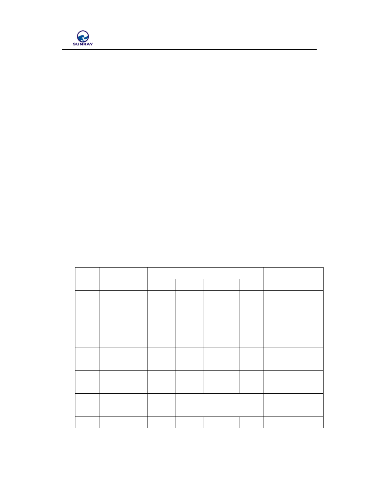
2. ElectricCharacteristicsandParameter
No. Description
Parameter
Notes
Unit Min Typical Max
1 Power supply V 3.2 3.6 4.0
Power type lithium
thionyl chloride
battery
2
Working
current
uA 110 120
3
Reading
interval
S 1 1.5
4
Working
temperature
℃ -25 25 65
5
Transmit
Frequency
MHz 470
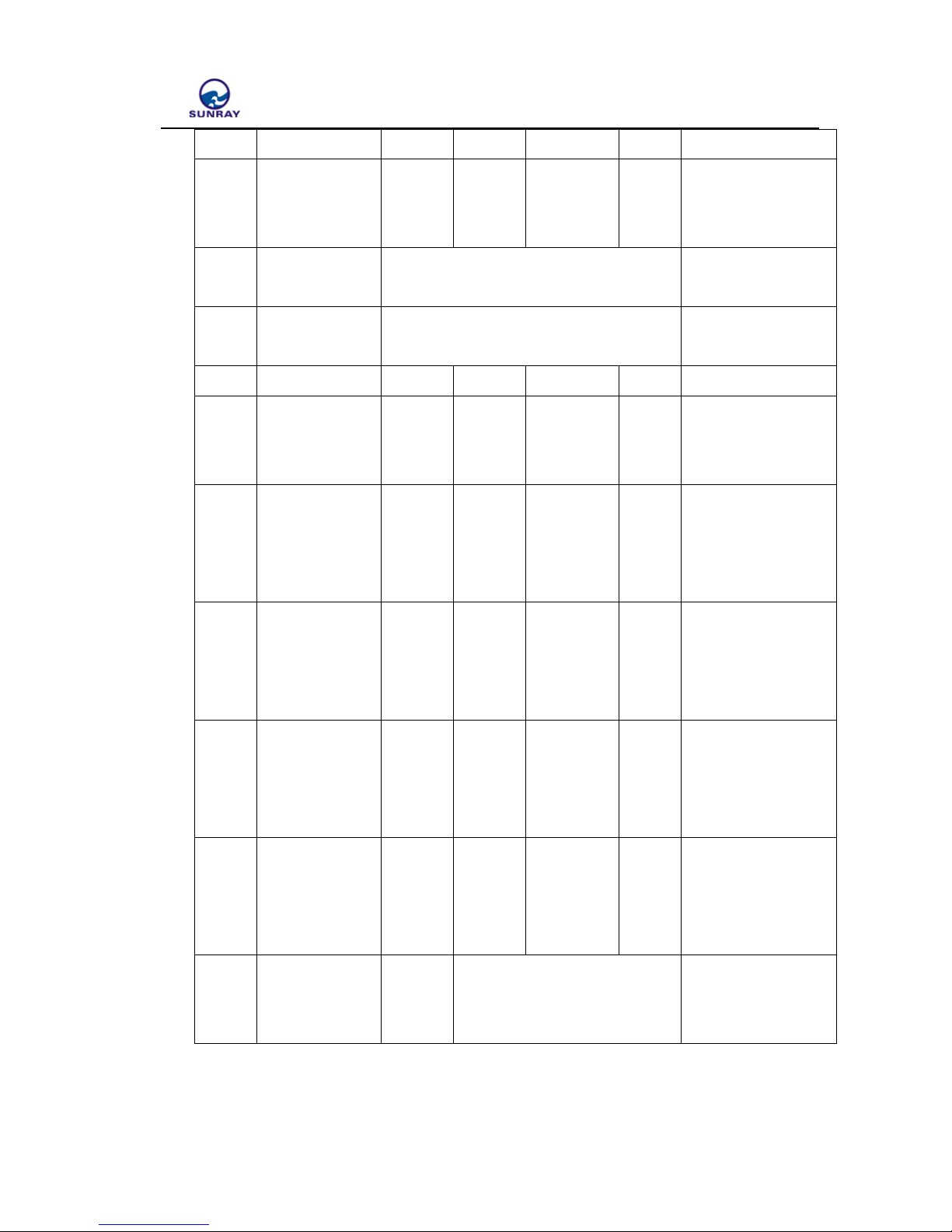
6 Transmit dBm 18 19 20
ShangHai Sunray Technology Co.,Ltd
4 / 17
power
7
Reliable
Transmitting
Distance
m 200 250 Open field
8
Modulation
mode
GFSK/FSK
9 Channel 1
User can’t set the
channel
10
Lifetime
year 10
11
Driving
current of
valve
mA 100 250
12
Reed switch
module pin
pull-up
resistors
KΩ 1.98 2 2.02
13
Hall
component pin
input
impedance
MΩ 60
14
Photoelectric
direct reading
module output
voltage
V 3.2 3.6 4
15
Photoelectric
direct reading
module output
current
mA 100
Photoelectric meter
power supply
16
UART Port
compatibility
level
V 3
ShangHai Sunray Technology Co.,Ltd
5 / 17
3. SoftwareFunction
3.1. Measurement
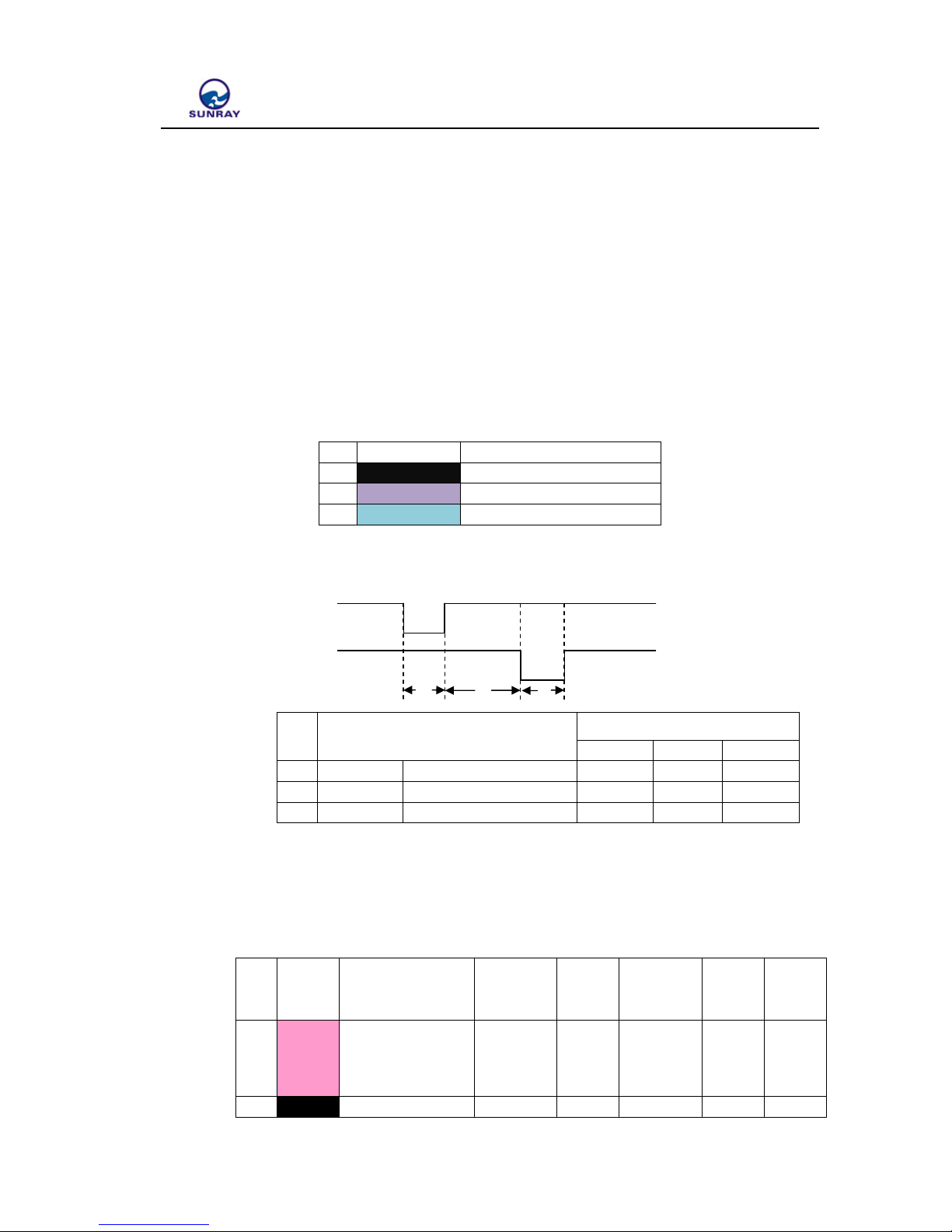
3.1.1. Double Reed Switch
3.1.1.1 Reed switch module pin connection
NO Wire Colour Pin Function
1 Black Common Ground
2 Purple Reed switch B
3 Green Reed switch A
3.1.1.2 A、B Reed switch pulse input timing diagram
A Reed switch
B Reed switch
t1 t2 t3
NO State
Input low pulse time requirement
Min Typ Max
1 t1 A Closing Time 1.5S
2 t2 AB opening Time 1S
3 t3 B Closing Time 1.5S
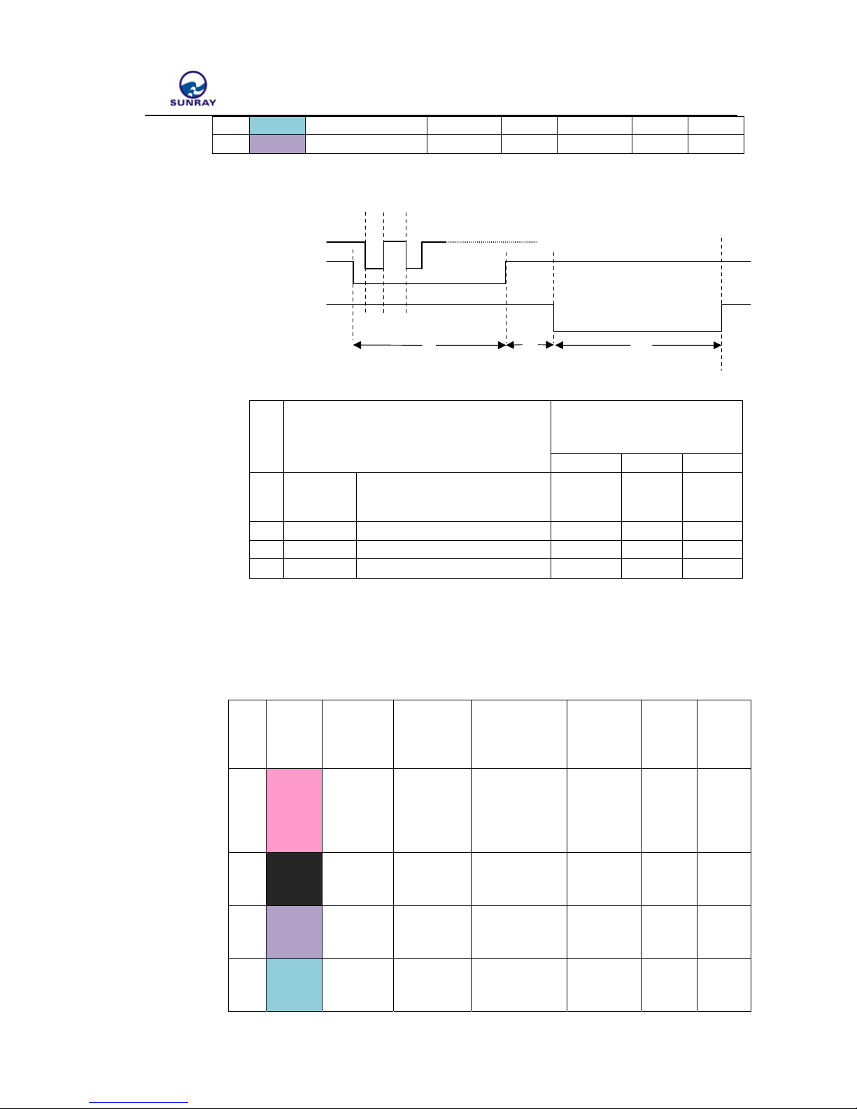
3.1.2. Double Hall Component
3.1.2.1 Hall module pin connection
NO
Wire
Color
Pin Function
Test
Frequency
Max
driving
current
Power
supply
fre
q
uency
Output
level
Input
level
1 Pink
Hall power supply
terminal
1.5mA
(Vcc-
0.25)
10Hz
3V
2 Black Common Ground
ShangHai Sunray Technology Co.,Ltd
6 / 17
3
Green Hall Input B 10Hz CMOS
4 Purple Hall Input A 10Hz CMOS
3.1.2.2 Parameter Requirements of Hall Component
VDD
Hall A t1 t2
Hall B
t3 t4 t5
NO State
Input low pulse time
requirement
Min Typ Max
1 t1
Hall meter head power supply
time
16mS
2 t2 Detection interval 100mS
3 t3、t5 Hall low time 1.5S
4 t4 Two Hall high time 1S
3.1.3. Three Hall Element
3.1.3.1 Double hall module pin connection
NO
Wire
Color
Pin
Function
Test
Frequency
Maximal
driving
Current
Power
supply
frequency
Output
level
Input
level
1 Pink
Hall
power
supply
terminal
1.5mA(VCC-
0.25)
10Hz 3V
2 Black
Common
Ground
3
Purple
Hall Input
B
10Hz
CMOS
4
Green
Hall Input
A
10Hz
CMOS
 Loading...