

Shanghai High-Flying Electronics Technology Co. HF-LPT120 User Manual
High-Flying
HF-LPT120 Low Power WiFi Module User Manual
HF-LPT120
Low Power WiFi Module User Manual
V 1.1.1
Overview of Characteristic
Support IEEE802.11b/g/n Wireless Standards
Based on Self-developed High Cost Effective SOC
Support UART/GPIO Data Communication Interface
Support Work As STA/AP Mode
Support Smart Link Function (APP program provide)
Support Wireless and Remote Firmware Upgrade Function
support WPS Function
Support External I-PEX or Internal PCB Antenna Option
Single +3.3V Power Supply
Smallest Size: 22mm x 13.5mm x 6mm, 1x10 2mm Connector
FCC/CE Certificated
Shanghai High-Flying Electronics Technology Co., Ltd(www.hi-flying.com) - 1 -

High-Flying
HF-LPT120 Low Power WiFi Module User Manual
TABLE OF CONTENTS
LIST OF FIGURES ................................................................................................................................... 6
LIST OF TABLES .................................................................................................................................... 7
HISTORY .................................................................................................................................................. 8
1. PRODUCT OVERVIEW ................................................................................................................ 9
1.1. General Description ................................................................................................................. 9
1.1.1 Device Features .................................................................................................................. 9
1.1.2 Device Paremeters ...........................................................................................................10
1.1.3 Key Application .................................................................................................................10
1.2. Hardware Introduction ...........................................................................................................11
1.2.1. Pins Definition ...................................................................................................................11
1.2.2. Electrical Characteristics ..................................................................................................12
1.2.3. Mechanical Size ................................................................................................................13
1.2.4. On-board PCB Antenna ....................................................................................................14
1.2.5. External Antenna ..............................................................................................................14
1.2.6. Evaluation Kit ....................................................................................................................15
1.2.7. Order Information ..............................................................................................................16
1.3. Typical Application ................................................................................................................17
1.3.1. Hardware Typical Application ...........................................................................................17
1.4. Internal PCB Antenna ............................................................................................................18
2. FUNCTIONAL DESCRIPT ION ..................................................................................................20
2.1. Wireless Networking ..............................................................................................................20
2.1.1. Basic Wireless Network Based On AP (Infrastructure) ....................................................20
2.1.2. Wireless Network Based On STA .....................................................................................20
2.2. Work Mode : Transparent Transmission Mode ...................................................................21
2.3. UART Frame Scheme(Reserved) ..........................................................................................21
2.3.1. UART Free-Frame ............................................................................................................21
2.3.2. UART Auto-Frame ............................................................................................................22
2.4. Encryption ..............................................................................................................................22
2.5. Parameters Configuration .....................................................................................................22
2.6. Firmware Update(Reserved, See Appendix C) ...............................................................22
2.7. SOCKET B Function ..............................................................................................................23
2.8. Multi-TCP Link Connection (Reserved) ...............................................................................24
3. OPERATIO N GUIDELINE ..........................................................................................................25
3.1. Default Parameter ..................................................................................................................25
3.2. HF-LPT120 Usage Introduction ............................................................................................25
3.2.1. Software Debug Tools ......................................................................................................25
3.2.2. Network Connection .........................................................................................................25
3.2.3. Default Parameter Setting ................................................................................................26
3.2.4. Module Debug...................................................................................................................26
Shanghai High-Flying Electronics Technology Co., Ltd(www.hi-flying.com) - 2 -

High-Flying
HF-LPT120 Low Power WiFi Module User Manual
3.3. Typical Application Examples ..............................................................................................27
3.3.1. Wireless Control Application .............................................................................................27
3.3.2. Remote Management Application.....................................................................................28
3.3.3. Transparent Serial Port Application ..................................................................................28
4. AT+INSTRUCTION INTR O DUCTION ......................................................................................29
4.1. Configuration Mode ...............................................................................................................29
4.1.1. Switch to Configuration Mode ...........................................................................................29
4.2. AT+ Instruction Set Overview ...............................................................................................30
4.2.1. Instruction Syntax Format .................................................................................................30
4.2.2. AT+Instruction Set ............................................................................................................31
4.2.2.1. AT+E .............................................................................................................................33
4.2.2.2. AT+WMODE .................................................................................................................34
4.2.2.3. AT+ENTM .....................................................................................................................34
4.2.2.4. AT+TMODE ...................................................................................................................34
4.2.2.5. AT+MID .........................................................................................................................34
4.2.2.6. AT+VER ........................................................................................................................35
4.2.2.7. AT+LVER ......................................................................................................................35
4.2.2.8. AT+FWSZ .....................................................................................................................35
4.2.2.9. AT+RELD ......................................................................................................................35
4.2.2.10. AT+FCLR ...................................................................................................................35
4.2.2.11. AT+Z ..........................................................................................................................36
4.2.2.12. AT+H .........................................................................................................................36
4.2.2.13. AT+CFGTF ................................................................................................................36
4.2.2.14. AT+UART ..................................................................................................................36
4.2.2.15. AT+UARTF ................................................................................................................37
4.2.2.16. AT+UARTFT ..............................................................................................................37
4.2.2.17. AT+UARTFL ..............................................................................................................37
4.2.2.18. AT+UARTTE ..............................................................................................................38
4.2.2.19. AT+SEND ..................................................................................................................38
4.2.2.20. AT+RECV ..................................................................................................................38
4.2.2.21. AT+PING ...................................................................................................................38
4.2.2.22. AT+NETP ..................................................................................................................39
4.2.2.23. AT+MAXSK ...............................................................................................................39
4.2.2.24. AT+TCPLK ................................................................................................................40
4.2.2.25. AT+TCPTO ................................................................................................................40
4.2.2.26. AT+TCPDIS ...............................................................................................................40
4.2.2.27. AT+SOCKB ...............................................................................................................41
4.2.2.28. AT+TCPDISB ............................................................................................................41
4.2.2.29. AT+TCPTOB .............................................................................................................41
4.2.2.30. AT+TCPLKB ..............................................................................................................42
4.2.2.31. AT+SNDB ..................................................................................................................42
4.2.2.32. AT+RCVB ..................................................................................................................42
4.2.2.33. AT+WSSSID ..............................................................................................................43
4.2.2.34. AT+WSKEY ...............................................................................................................43
Shanghai High-Flying Electronics Technology Co., Ltd(www.hi-flying.com) - 3 -

High-Flying
HF-LPT120 Low Power WiFi Module User Manual
4.2.2.35. AT+WANN .................................................................................................................43
4.2.2.36. AT+WSMAC ..............................................................................................................44
4.2.2.37. AT+WSLK ..................................................................................................................44
4.2.2.38. AT+WSLQ .................................................................................................................44
4.2.2.39. AT+WSCAN ...............................................................................................................45
4.2.2.40. AT+WSDNS ...............................................................................................................45
4.2.2.41. AT+LANN ..................................................................................................................45
4.2.2.42. AT+WAP ....................................................................................................................45
4.2.2.43. AT+WAKEY ...............................................................................................................46
4.2.2.44. AT+WAMAC ..............................................................................................................46
4.2.2.45. AT+WADHCP ............................................................................................................46
4.2.2.46. AT+WADMN ..............................................................................................................47
4.2.2.47. AT+WALK ..................................................................................................................47
4.2.2.48. AT+WALKIND ............................................................................................................47
4.2.2.49. AT+OTA .....................................................................................................................48
4.2.2.50. AT+UPURL ................................................................................................................48
4.2.2.51. AT+UPFILE ...............................................................................................................48
4.2.2.52. AT+LOGSW ...............................................................................................................48
4.2.2.53. AT+LOGPORT ..........................................................................................................49
4.2.2.54. AT+UPST ..................................................................................................................49
4.2.2.55. AT+DISPS .................................................................................................................49
4.2.2.56. AT+NTPRF ................................................................................................................50
4.2.2.57. AT+NTPEN ................................................................................................................50
4.2.2.58. AT+NTPTM ................................................................................................................50
4.2.2.59. AT+NTPSER .............................................................................................................50
4.2.2.60. AT+WRMID ...............................................................................................................51
4.2.2.61. AT+RLDEN ................................................................................................................51
4.2.2.62. AT+ASWD .................................................................................................................51
4.2.2.63. AT+MDCH .................................................................................................................51
4.2.2.64. AT+TXPWR ...............................................................................................................52
4.2.2.65. AT+SMTLK ................................................................................................................52
4.2.2.66. AT+SMTLKVER .........................................................................................................52
4.2.2.67. AT+WPS ....................................................................................................................53
4.2.2.68. AT+WPSBTNEN ........................................................................................................53
4.2.2.69. AT+LPTIO ..................................................................................................................54
4.2.2.70. AT+WIFI ....................................................................................................................54
4.2.2.71. AT+SMEM .................................................................................................................54
4.2.2.72. AT+NDBGL ................................................................................................................55
5. PACKAGE INFORMATION ........................................................................................................56
5.1. Recommended Reflow Profile ..............................................................................................56
5.2. Device Handling Instruction (Module IC SMT Preparation) ...............................................56
5.3. Shipping Information .............................................................................................................57
APPENDIX A: HW REFEREN CE DESIGN ......................................................................................58
Shanghai High-Flying Electronics Technology Co., Ltd(www.hi-flying.com) - 4 -

High-Flying
HF-LPT120 Low Power WiFi Module User Manual
APPENDIX B: HTTP PROTO COL TRANSFER ..............................................................................59
B.1. HTTP AT command(Reserved) ................................................................................................59
B.1.1 AT+HTTPURL ...................................................................................................................59
B.1.2 AT+HTTPTP .....................................................................................................................59
B.1.3 AT+HTTPPH .....................................................................................................................59
B.1.4 AT+HTTPCN .....................................................................................................................60
B.1.5 AT+HTTPUA .....................................................................................................................60
B.1.6 AT+HTTPDT .....................................................................................................................60
B.2. HTTP Example ...........................................................................................................................60
B.3. Sending HTTP Raw Data in Throughput Mode(Recommend) ..............................................61
B.4. Sending HTTP Request By AT Command ..............................................................................62
APPENDIX C:R EFER ENCES ............................................................................................................64
C.1.High-Flying Mass Production Tool ........................................................................................64
C.2.SmartLink APP V7 Config Tool ..............................................................................................64
C.3.EVK Quick Start Guide ...........................................................................................................64
C.4.Module Upgrade ......................................................................................................................64
APPENDIX D: CONTACT INFORMATION ......................................................................................65
Shanghai High-Flying Electronics Technology Co., Ltd(www.hi-flying.com) - 5 -

High-Flying
HF-LPT120 Low Power WiFi Module User Manual
LIST OF FIGURES
Figure 1. HF-LPT120 Pins Map ...........................................................................................................11
Figure 2. HF-LPT120 Mechanical Dimension......................................................................................13
Figure 3. HF-LPT120-A Mechanical Dimension ..................................................................................13
Figure 4. Suggested Module Placement Region .................................................................................14
Figure 5. HF-LPT120 External Antenna picture ..................................................................................14
Figure 6. HF-LPT120 Evaluation Kit ....................................................................................................15
Figure 7. HF-LPT120 Order Information ..............................................................................................16
Figure 8. HF-LPT120 Hardware Typical Application ...........................................................................17
Figure 9. HF-LPT120 Antenna ............................................................................................................18
Figure 10. HF-LPT120 Antenna radiation pattern ..............................................................................18
Figure 11. HF-LPT120 XY plane radiation pattern ............................................................................19
Figure 12. HF-LPT120XZ plane radiation pattern ..............................................................................19
Figure 13. HF-LPT120YZ plane radiation pattern ..............................................................................19
Figure 14. HF-LPT120 Basic Wireless Network Structure .................................................................20
Figure 15. HF-A11 AP+STA Network Structure .................................................................................20
Figure 16. Socket B function demo ....................................................................................................24
Figure 17. Multi-TCP Link Data Transmition Structure ......................................................................24
Figure 18. STA Interface Debug Connection .....................................................................................25
Figure 19. AP Interface Debug Connection .......................................................................................26
Figure 20. ―CommTools‖ Serial Debug Tools ....................................................................................26
Figure 21. ―TCPUDPDbg‖ Tools Create Connection .........................................................................26
Figure 22. ―TCPUDPDbg‖ Tools Setting ............................................................................................27
Figure 23. ―TCPUDPDbg‖ Tools Connection .....................................................................................27
Figure 24. Wireless Control Application .............................................................................................27
Figure 25. Remote Management Application.....................................................................................28
Figure 26. Transparent Serial Port Application ..................................................................................28
Figure 27. HF-LPT120 Default UART Port Parameters .....................................................................29
Figure 28. Switch to Configuration Mode ...........................................................................................29
Figure 29. ‖AT+H‖ Instruction for Help ...............................................................................................30
Figure 30. Reflow Soldering Profile ...................................................................................................56
Figure 31. Shipping Information .........................................................................................................57
Shanghai High-Flying Electronics Technology Co., Ltd(www.hi-flying.com) - 6 -

High-Flying
HF-LPT120 Low Power WiFi Module User Manual
LIST OF TABLES
Table 1 HF-LPT120 Module Technical Specifications .......................................................................10
Table 2 HF-LPT120 Pins Definition ....................................................................................................11
Table 3 Absolute Maximum Ratings: ..................................................................................................12
Table 4 Power Supply & Power Consumption: ..................................................................................12
Table 5 HF-LPT120 External Antenna Parameters ...........................................................................14
Table 6 HF-LPT120 Evaluation Kit Interface Description ...................................................................15
Table 8 HF-LPT120 Default Setting ...................................................................................................25
Table 9 Error Code Describtion ..........................................................................................................31
Table 10 AT+Instruction Set List ........................................................................................................31
Table 11 Reflow Soldering Parameter .................................................................................................56
Shanghai High-Flying Electronics Technology Co., Ltd(www.hi-flying.com) - 7 -

High-Flying
HF-LPT120 Low Power WiFi Module User Manual
HISTORY
Ed. V1.02 11-03-2015 First Version.
Ed. V1.03 11-11-2015 Modify IO PIN Description.
Ed. V1.04 11-27-2015 Change Module PCB.
Ed. V1.1 12-21-2015 Update AT command supported by 2.0.01 version firmware.
Ed. V1.1.1 01-04-2016 Add HF-LPT100-A Type.
Shanghai High-Flying Electronics Technology Co., Ltd(www.hi-flying.com) - 8 -

High-Flying
HF-LPT120 Low Power WiFi Module User Manual
1. PRODUCT OVERVIEW
1.1. General Description
The HF-LPT120 is a fully self-contained small form-factor, single stream, 802.11b/g/n Wi-Fi module,
which provide a wireless interface to any equipment with a Serial/PWM interface for data transfer.HF-
LPT120 integrate MAC, baseband processor, RF transceiver with power amplifier in hardware and all
Wi-Fi protocol and configuration functionality and networking stack, in embedded firmware to make a
fully self-contained 802.11b/g/n Wi-Fi solution for a variety of applications.
The HF-LPT120 employs the world's lowest power consumption embedded architecture. It has been
optimized for all kinds of client applications in the home automation, smart grid, handheld device,
personal medical application and industrial control that have lower data rates, and transmit or receive
data on an infrequent basis.
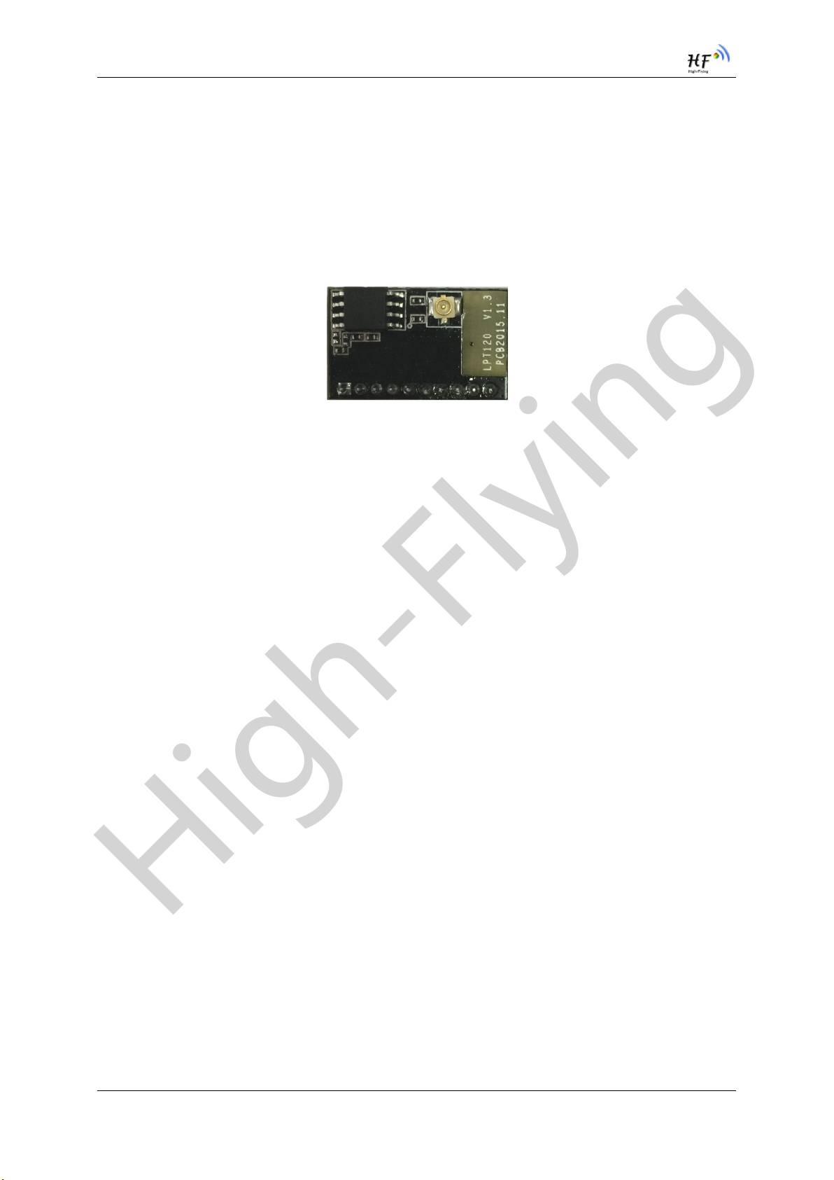
The HF-LPT120 integrates all Wi-Fi functionality into a low-profile, 22mm x 13.5mm x 6mm module
package that can be easily mounted on main PCB with application specific circuits. Also, module
provides built-in antenna, external antenna option.
1.1.1 Device Features
Single stream Wi-Fi @ 2.4 GHz with support for WEP security mode as well as WPA/WPA2
Based on Self-developed High Cost Performance SOC
Includes all the protocol and configuration functions for Wi-Fi connectivity.
Support STA/AP Mode
Support Smart Link Function
Support Wireless and Remote Firmware Upgrade Function
Support External I-PEX or Internal PCB antenna connector options.
Compact surface mount module 22mm x 13.5mm x 6mm
Single supply – 3.3V operation.
FCC/CE Certified.
RoHS Compliant.
Shanghai High-Flying Electronics Technology Co., Ltd(www.hi-flying.com) - 9 -

High-Flying
HF-LPT120 Low Power WiFi Module User Manual
Class
Item
Parameters
Wireless
Parameters
Certification
FCC/CE
Wireless standard
802.11 b/g/n
Frequency range
2.412GHz-2.484GHz
Transmit Power
802.11b: +16 +/-2dBm (@11Mbps)
802.11g: +14 +/-2dBm (@54Mbps)
802.11n: +13 +/-2dBm (@HT20, MCS7)
Receiver Sensitivity
802.11b: -93 dBm (@11Mbps ,CCK)
802.11g: -85 dBm (@54Mbps, OFDM)
802.11n: -82 dBm (@HT20, MCS7)
Antenna Option
External:I-PEX Connector
Internal:PCB Printed Antenna
Hardware
Parameters
Data Interface
UART
GPIO
Operating Voltage
2.95~3.6V
Operating Current
Peak [Continuous TX]: ~280mA
Average. ~20mA
Operating Temp.
-20℃- 85℃
Storage Temp.
-40℃- 125℃
Dimensions and Size
22mm x 13.5mm x 6mm
External Interface
1x10, 2mm DIP
Software
Parameters
Network Type
STA /AP
Security Mechanisms
WEP/WPA-PSK/WPA2-PSK
Encryption
WEP64/WEP128/TKIP/AES
Update Firmware
Local Wireless, Remote
Customization
Support customization
Network Protocol
IPv4, TCP/UDP/HTTP
User Configuration
AT+instruction set. Android/ iOS
Smart Link APP tools
1.1.2 Device Paremeters
Table 1 HF-LPT120 Module Technical Specifications
1.1.3 Key Application
Remote equipment monitoring
Asset tracking and telemetry
Security
Industrial sensors and controls
Home automation
Medical devices
Shanghai High-Flying Electronics Technology Co., Ltd(www.hi-flying.com) - 10 -

High-Flying
HF-LPT120 Low Power WiFi Module User Manual
Pin
Description
Net Name
Signal
Type
Comments
1
Ground
GND
Power
2
+3.3V Power
DVDD
Power
3.3V@300mA
3
Restore
Configuration
nReload
I/O,PU
Can be configured as GPIO_2
Detailed functions see <Notes>
4
Module Reset
EXT_RESETn
I,PU
―Low‖ effective reset input.
5
UART0
UART0_RX I GPIO_19
6
UART0
UART0_TX
O,PU
GPIO_20
7
GPIO_5
GPIO_5
I/O
Can be configured as UART0_RTS,
UART1_TXD,GPIO_5
8
GPI_6
GPIO_6
I/O
Can be configured as UART0_CTS,
UART1_RXD,GPIO_6
9
GPIO_3
nReady
I/O
Can be configured as nReady,GPIO
10
GPIO_15
nLink
I/O
Can be configured as nLink,GPIO
Detailed functions see <Notes>
1.2. Hardware Introduction
1.2.1. Pins Definition
Figure 1. HF-LPT120 Pins Map
Table 2 HF-LPT120 Pins Definition
I—Input, O—Output,PU—Internal Pullup Resistor; I/O: Digital I/O;Power—Power
<Notes>
nReload Pin (Button) function:
1. When this pin is set to “low” during module boot up, the module will enter wireless
firmware and config upgrade mode. This mode is used for customer manufacture.
Shanghai High-Flying Electronics Technology Co., Ltd(www.hi-flying.com) - 11 -
High-Flying
HF-LPT120 Low Power WiFi Module User Manual
Parameter
Condition
Min.
Typ.
Max.
Unit
Storage temperature range
-40 125
°C
Maximum soldering temperature
IPC/JEDEC J-STD-020
260
°C
Supply voltage
0 3.6
V
Voltage on any I/O pin
0
3.6
V
ESD (Human Body Model HBM)
TAMB=25°C
2.5
KV
ESD (MM)
TAMB=25°C
0.25
KV
Parameter
Condition
Min.
Typ.
Max.
Unit
Operating Supply voltage
2.95
3.3
3.6
V
Supply current, peak
Continuous Tx
280 mA
Supply current, IEEE PS
DTIM=100ms
20 mA
(See Appendix D to download software tools for customer batch configuration and
upgrade firmware during mass production)
2. After module is powered up, short press this button ( “Low” < 2s ) to make the
module go into “Smart Link “ config mode, waiting for APP to set password and
other information. (See Appendix D to download SmartLink APP)
3. After module is powered up, long press this button ( “Low” > 4s ) to make the
module recover to factory setting.
High-Flying strongly suggest customer fan out this pin to connector or button for
“Manufacture” and “ Smart Link” application.
nLink Pin (LED) function:
1. At wireless firmware and config upgrade mode , this LED used to indicate configure
and upgrade status.
2. At “Smart Link “ config mode, this LED used to indicate APP to finish setting.
3. At normal mode, it’s Wi-Fi link status indicator
High-Flying strongly suggest customer fan out this pin to LED.
1.2.2. Electrical Characteristics
Table 3 Absolute Maximum Ratings:
Table 4 Power Supply & Power Consumption:
Shanghai High-Flying Electronics Technology Co., Ltd(www.hi-flying.com) - 12 -
High-Flying
HF-LPT120 Low Power WiFi Module User Manual
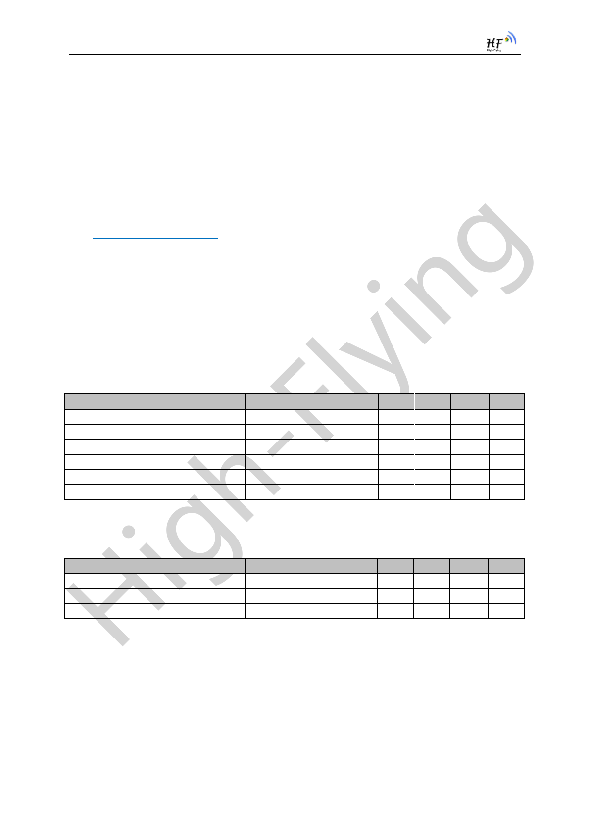
1.2.3. Mechanical Size
HF-LPT120 modules physical size (Unit: mm) as follows:
Figure 2. HF-LPT120 Mechanical Dimension
Figure 3. HF-LPT120-A Mechanical Dimension
Shanghai High-Flying Electronics Technology Co., Ltd(www.hi-flying.com) - 13 -
High-Flying
HF-LPT120 Low Power WiFi Module User Manual
Item
Parameters
Frequency range
2.4~2.5GHz
Impedance
50 Ohm
VSWR
2 (Max)
Return Loss
-10dB (Max)
Connector Type
I-PEX or populate directly
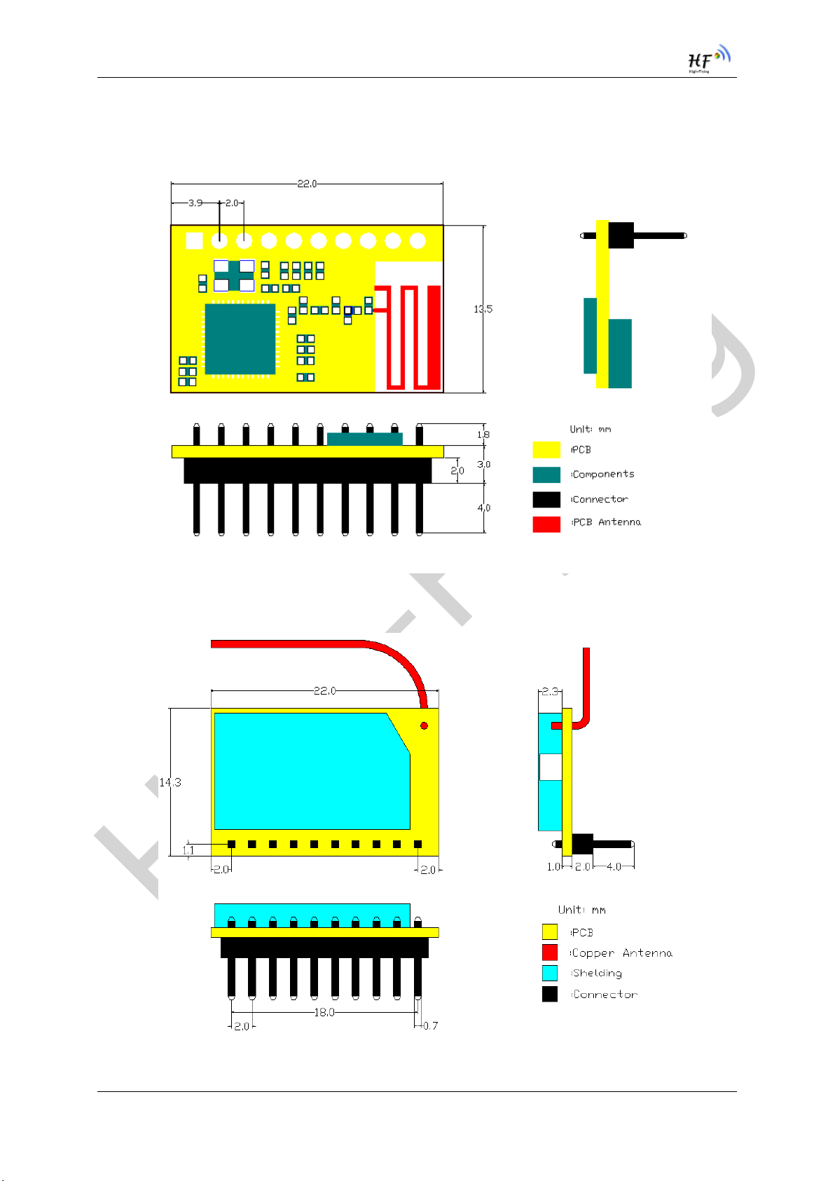
1.2.4. On-board PCB Antenna
HF-LPT120 module support internal on-board PCB antenna option. When customer select internal
antenna, you shall comply with following antenna design rules and module location suggestions:
For customer PCB, RED color region (8x10mm) can’t put componet or paste GND net;
Antenna must away from metal or high components at least 10mm;
Antenna can’t be shielded by any metal enclosure;
Figure 4. Suggested Module Placement Region
High-Flying suggest HF-LPB100 module better locate in following region at customer board, which to
reduce the effect to antenna and wireless signal, and better consult High-Flying technical people when
you structure your module placement and PCB layout.
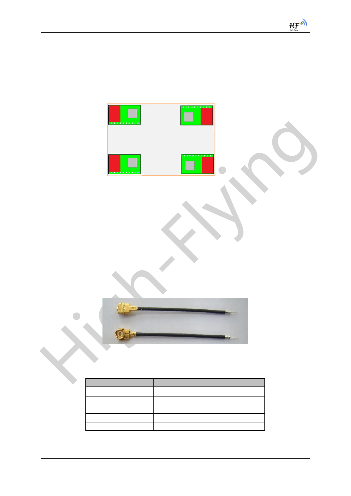
1.2.5. External Antenna
HF-LPT120 supports two way of external antenna as the following picture show, The I-PEX interface
or the PAD interface(remove the I-PEX connector). The user may choose one of them. If user select
external antenna, HF-LPT120 modules must be connected to the 2.4G antenna according to IEEE
802.11b/g/n standards.
The antenna parameters required as follows:
Figure 5. HF-LPT120 External Antenna picture
Table 5 HF-LPT120 External Antenna Parameters
Shanghai High-Flying Electronics Technology Co., Ltd(www.hi-flying.com) - 14 -
High-Flying
HF-LPT120 Low Power WiFi Module User Manual
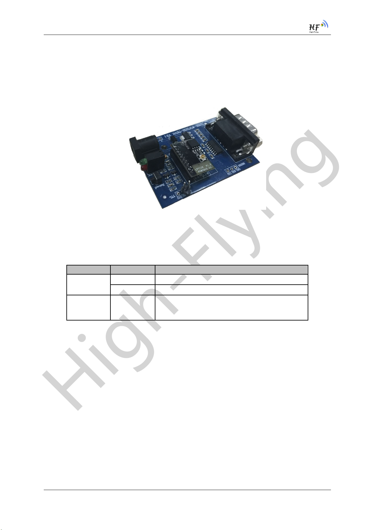
Function
Name
Description
External
Interface
RS232
Main data/command RS-232 interface
DC5V
DC jack for power in, 5V input.
Button
nReload
Restore factory default configuration after push this
pin more than 4s.
See 1.2.1
1.2.6. Evaluation Kit
High-Flying provides the evaluation kit to promote user to familiar the product and develop the detailed
application. The evaluation kit shown as below, user can connect to HF-LPT120 module with the RS-
232 UART, or Wireless interface to configure the parameters, manage the module or do the some
functional tests. The EVK support .5V DC power supply.
Figure 6. HF-LPT120 Evaluation Kit
The external interface description for evaluation kit as follows:
Table 6 HF-LPT120 Evaluation Kit Interface Description
Shanghai High-Flying Electronics Technology Co., Ltd(www.hi-flying.com) - 15 -
High-Flying
HF-LPT120 Low Power WiFi Module User Manual
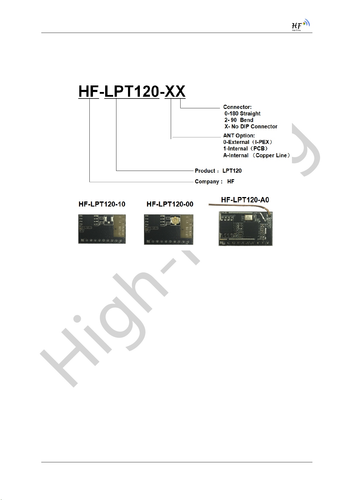
1.2.7. Order Information
Base on customer detailed requirement, HF-LPT120 series modules provide different variants and
physical type for detailed application.
Figure 7. HF-LPT120 Order Information
Shanghai High-Flying Electronics Technology Co., Ltd(www.hi-flying.com) - 16 -
High-Flying
HF-LPT120 Low Power WiFi Module User Manual
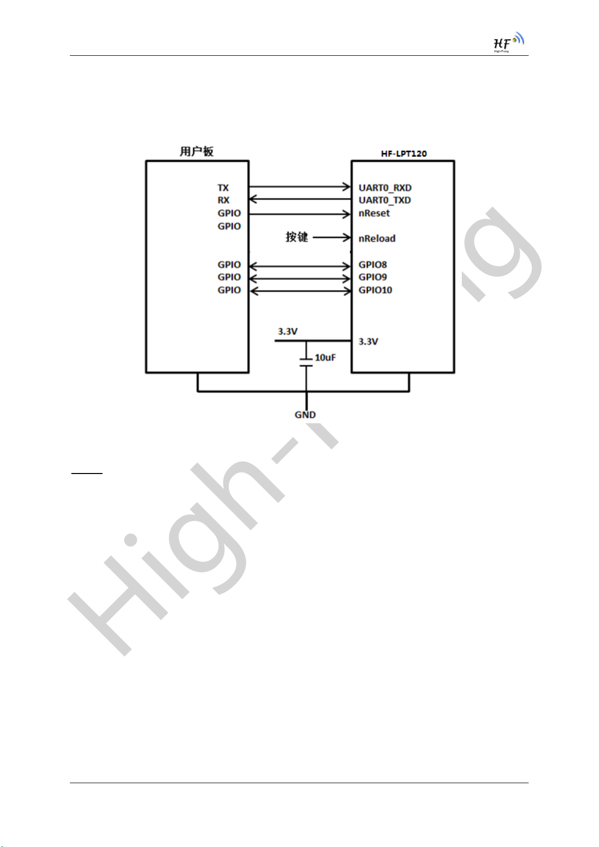
1.3. Typical Application
1.3.1. Hardware Typical Application
Figure 8. HF-LPT120 Hardware Typical Application
Notes:
nReset- Module hardware reset signal. Input. Logics ―0‖ effective.
There is pull-up resister internal and no external pull-up required. When module power up or some
issue happened, MCU need assert nRST signal ―0‖ at least 10ms, then set‖ 1‖ to keep module fully
reset.
nReady- Module boot up ready signal. Output. Logics ―0‖ effective.
The module will output ―0‖ after normal boot up. This signal used to judge if module finish boot up and
ready for application or working at normal mode. If nReady function not required, can leave this pin
open.
nReload- Module restore to factory default configuration.Input. Logics ―0‖ effective.
(This pin is recommend to connect to button, is used to enter wireless upgrade mode)
User can de-assert nReload signal ―0‖ more than 4s through button or MCU pin, then release, module
will restore to factory default configuration and re-start boot up process.. If nReload function not
required, can leave this pin open.
UART0_TXD/RXD- UART port data transmit and receive signal.
nLink- Module WIFI connection status indication. Output.
Shanghai High-Flying Electronics Technology Co., Ltd(www.hi-flying.com) - 17 -
High-Flying
HF-LPT120 Low Power WiFi Module User Manual
(This pin is recommend to connect to LED, indicate status when the module in wireless
upgrade mode)
When module connects to AP (AP associated), this pin will output ―0‖. This signal used to judge if
module already at WiFi connection status. Thers is pull-up resister internal and no external pull-up
required. If nLink function not required, can leave this pin open.
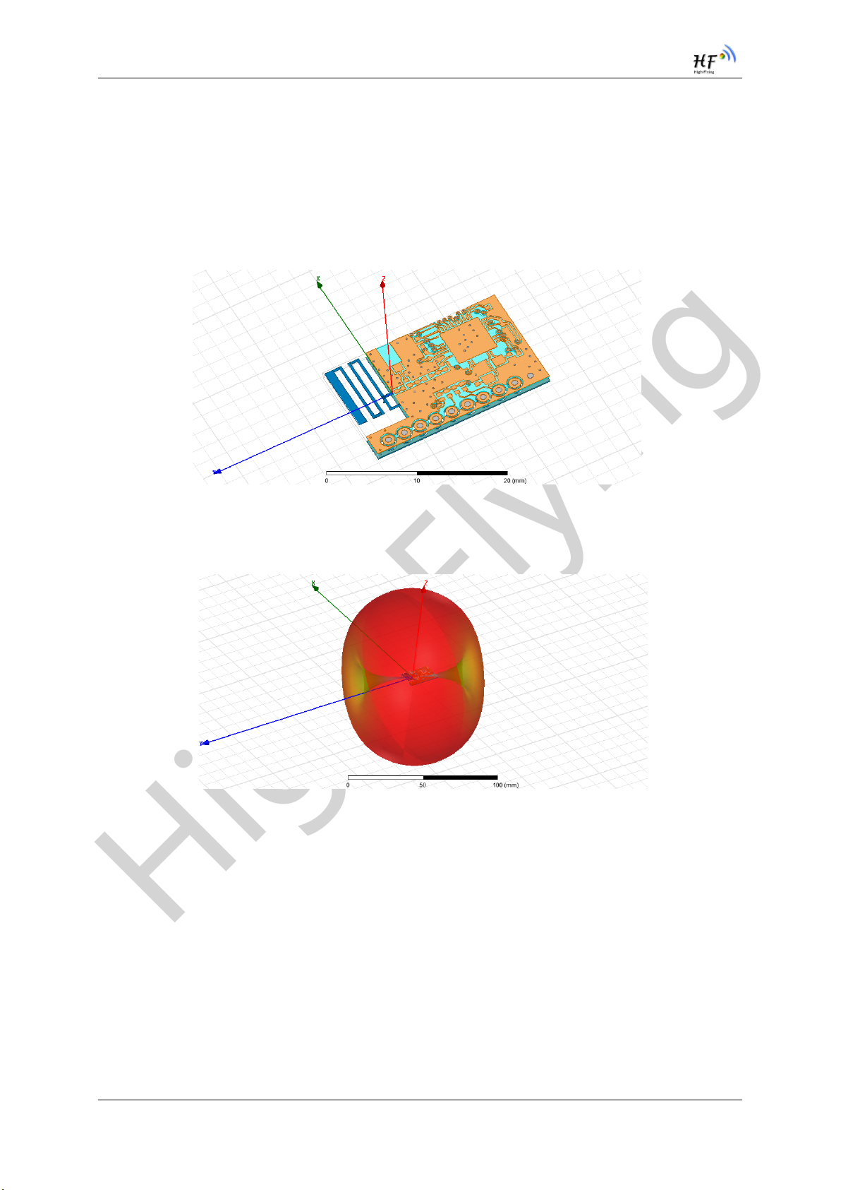
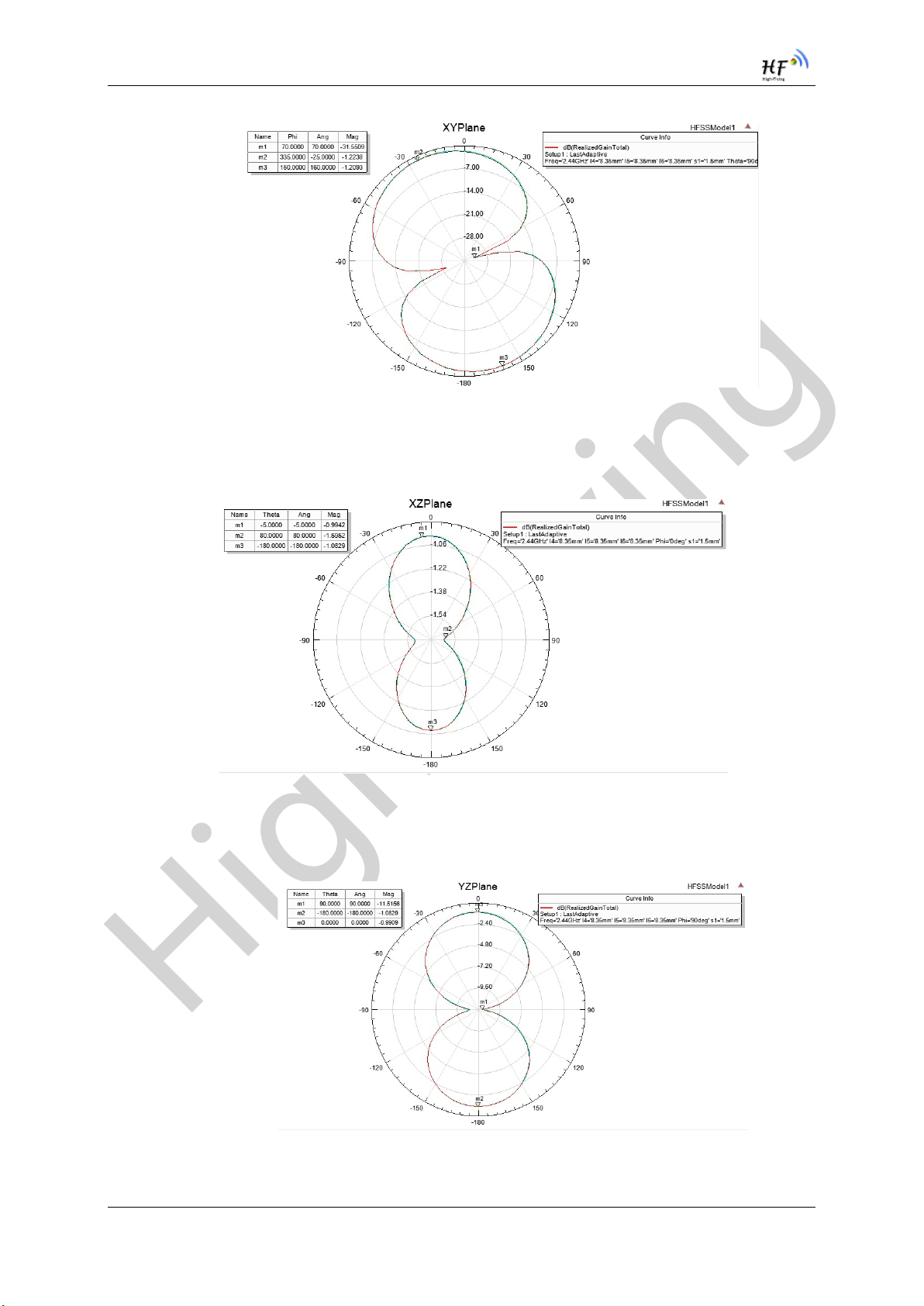
1.4. Internal PCB Antenna
Figure 9. HF-LPT120 Antenna
Antenna radiation efficiency 49.2%
Figure 10. HF-LPT120 Antenna radiation pattern
XY plane maximum gain:-1.21dB, minimum gain: -31.55dB
Shanghai High-Flying Electronics Technology Co., Ltd(www.hi-flying.com) - 18 -
High-Flying
HF-LPT120 Low Power WiFi Module User Manual
Figure 11. HF-LPT120 XY plane radiation pattern
XZ plane maximum gain:-0.99dB, minimum gain:-1.6dB
Figure 12. HF-LPT120XZ plane radiation pattern
YZ plane maximum gain:-0.99dB, minimum gain:-11.52dB
Figure 13. HF-LPT120YZ plane radiation pattern
Shanghai High-Flying Electronics Technology Co., Ltd(www.hi-flying.com) - 19 -
High-Flying
HF-LPT120 Low Power WiFi Module User Manual
2. FUNCTIONAL DESCRIPTION
2.1. Wireless Networking
HF-LPT120 module can be configured as both wireless STA and AP base on network type. Logically
there are two interfaces in HF-LPT120. One is for STA, and another is for AP. When HF-LPT120
works as AP, other STA equipments are able to connect to HF-LPT120 module directly. Wireless
Networking with HF-LPT120 is very flexible.
Notes:
AP: that is the wireless Access Point, the founder of a wireless network and the centre of the network
nodes. The wireless router we use at home or in office may be an AP.
STA: short for Station, each terminal connects to a wireless network (such as laptops, PDA and other
networking devices) can be called with a STA device.
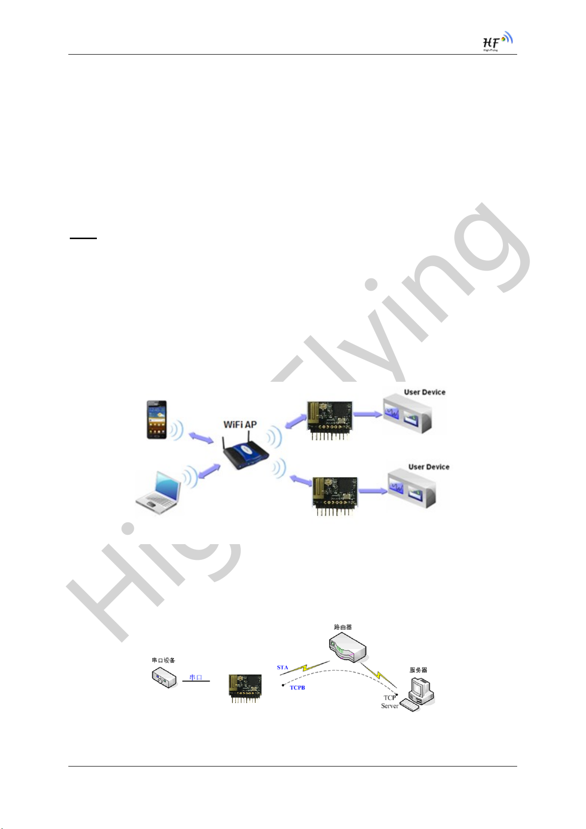
2.1.1. Basic Wireless Network Based On AP (Infrastructure)
Infrastructure: it’s also called basic network. It built by AP and many STAs which join in.
The characters of network of this type are that AP is the centre, and all communication between STAs
is transmitted through the AP. The figure following shows such type of networking.
Figure 14. HF-LPT120 Basic Wireless Network Structure
2.1.2. Wireless Network Based On STA
HF-LPT120 module support STA network mode as following figure,
Figure 15. HF-A11 AP+STA Network Structure
Shanghai High-Flying Electronics Technology Co., Ltd(www.hi-flying.com) - 20 -
 Loading...