


Version 1.3 Oct 18
JA Solar
th
, 2019
INSTALLATION MANUAL
FOR JA SOLAR PHOTOVOLTAIC MODULES
JAM6(K)-72-xxx/PR/1500V, xxx=345 to 370 in increment of 5;
JAM6(K)-60-xxx/PR/1500V, xxx=285 to 310 in increment of 5;
JAM6(K)-72-xxx/4BB/1500V, xxx=320 to 345 in increment of 5;
JAM6(K)-60-xxx/4BB/1500V, xxx=265 to 285 in increment of 5;
JAM72S03-xxx/PR, xxx= 360 to 395 in increment of 5;
JAM60S03-xxx/PR, xxx= 300 to 330 in increment of 5;
JAM72S01-xxx/PR, xxx= 345 to 390 in increment of 5;
JAM60S01-xxx/PR, xxx= 285 to 325 in increment of 5;
JAM72S01-xxx/SC, xxx= 320 to 365 in increment of 5;
JAM60S01-xxx/SC, xxx= 265 to 305 in increment of 5;
JAM72S01-xxx/MR/1500V, xxx= 365 to 385 in increment of 5;
JAM60S01-xxx/MR/1500V, xxx= 305 to 320 in increment of 5;
JAM72S09-xxx/PR/1500V, xxx= 370 to 405 in increment of 5
JAM60S09-xxx/PR/1500V, xxx= 310 to 335 in increment of 5;
JAM72S10-xxx/PR/1500V, xxx= 380 to 410 in increment of 5
JAM60S10-xxx/PR/1500V, xxx= 315 to 345 in increment of 5;
JAM72S10-xxx/MR/1500V, xxx= 390 to 420 in increment of 5
JAM60S10-xxx/MR/1500V, xxx= 320 to 345 in increment of 5;
JAM78S10-xxx/MR/1500V, xxx= 410 to 455 in increment of 5
JAM66S10-xxx/MR/1500V, xxx= 345 to 380 in increment of 5;
JAM6(K)-72-xxx/PR, xxx=345 to 370 in increment of 5;
JAM6(K)-60-xxx/PR, xxx=285 to 310 in increment of 5;
JAM6(K)-72-xxx/4BB, xxx=320 to 345 in increment of 5;
JA PV Module Installation Manual

Version 1.3 Oct 18
JA Solar
th
, 2019
JAM6(K)-60-xxx/4BB, xxx=265 to 285 in increment of 5;
JAM72S03-xxx/PR/1000V, xxx= 360 to 395 in increment of 5;
JAM60S03-xxx/PR/1000V, xxx= 300 to 330 in increment of 5;
JAM72S01-xxx/PR/1000V, xxx= 345 to 390 in increment of 5;
JAM60S01-xxx/PR/1000V, xxx= 285 to 325 in increment of 5;
JAM72S01-xxx/SC/1000V, xxx= 320 to 365 in increment of 5;
JAM60S01-xxx/SC/1000V, xxx= 265 to 305 in increment of 5;
JAM72S01-xxx/MR/1000V, xxx= 365 to 385 in increment of 5;
JAM60S01-xxx/MR/1000V, xxx= 305 to 320 in increment of 5;
JAM72S09-xxx/PR/1000V, xxx= 370 to 405 in increment of 5
JAM60S09-xxx/PR/1000V, xxx= 310 to 335 in increment of 5;
JAM72S10-xxx/PR/1000V, xxx= 380 to 410 in increment of 5
JAM60S10-xxx/PR/1000V, xxx= 315 to 345 in increment of 5;
JAM72S10-xxx/MR/1000V, xxx= 390 to 420 in increment of 5
JAM60S10-xxx/MR/1000V, xxx= 320 to 345 in increment of 5;
JAM78S10-xxx/MR/1000V, xxx= 410 to 455 in increment of 5
JAM66S10-xxx/MR/1000V, xxx= 345 to 380 in increment of 5;
JAM72S02-xxx/PR/1000V, xxx= 345 to 390 in increment of 5;
JAM60S02-xxx/PR/1000V, xxx= 285 to 325 in increment of 5;
JAM72S08-xxx/PR/1000V, xxx= 360 to 395 in increment of 5;
JAM60S08-xxx/PR/1000V, xxx= 300 to 330 in increment of 5;
JAM72S02-xxx/SC/1000V, xxx= 320 to 365 in increment of 5;
JAM60S02-xxx/SC/1000V, xxx= 265 to 305 in increment of 5;
JAM72S02-xxx/MR/1000V, xxx= 365 to 385 in increment of 5;
JAM60S02-xxx/MR/1000V, xxx= 305 to 320 in increment of 5;
JAM72S12-xxx/PR/1000V, xxx= 365 to 380 in increment of 5
JAM60S12-xxx/PR/1000V, xxx= 305 to 330 in increment of 5;
JA PV Module Installation Manual

Version 1.3 Oct 18
JA Solar
th
, 2019
JAM72S17-xxx/PR/1000V, xxx= 380 to 390 in increment of 5;
JAM60S17-xxx/PR/1000V, xxx= 315 to 325 in increment of 5;
JAM72S17-xxx/MR/1000V, xxx= 390 to 395 in increment of 5;
JAM60S17-xxx/MR/1000V, xxx= 315 to 325 in increment of 5;
JAP6(K)-72-xxx/4BB/1500V, xxx=310 to 330 in increment of 5;
JAP6(K)-60-xxx/4BB/1500V, xxx=255 to 275 in increment of 5;
JAP72S01-xxx/SC, xxx= 310 to 345 in increment of 5
JAP60S01-xxx/SC, xxx= 255 to 290 in increment of 5;
JAP72S01-xxx/PR, xxx=330 to 345 in increment of 5;
JAP60S01- xxx/PR, xxx=275 to 285 in increment of 5;
JAP72S03-xxx/SC, xxx= 320 to 345 in increment of 5;
JAP60S03-xxx/SC, xxx= 270 to 290 in increment of 5;
JAP72S03-xxx/PR, xxx= 335 to 355 in increment of 5;
JAP60S03-xxx/PR, xxx= 280 to 295 in increment of 5;
JAP72S09-xxx/SC/1500V, xxx= 320 to 345 in increment of 5;
JAP60S09-xxx/SC/1500V, xxx= 265 to 290 in increment of 5;
JAP72S10-xxx/SC/1500V, xxx= 335 to 350 in increment of 5;
JAP60S10-xxx/SC/1500V, xxx= 275 to 290 in increment of 5;
JAP72S02-xxx/SC/1000V, xxx= 310 to 345 in increment of 5;
JAP60S02-xxx/SC/1000V, xxx= 255 to 290 in increment of 5;
JAP72S02-xxx/PR/1000V, xxx=330 to 345 in increment of 5;
JAP60S02- xxx/PR/1000V, xxx=275 to 285 in increment of 5;
JAP72S08-xxx/SC/1000V, xxx= 320 to 345 in increment of 5;
JAP60S08-xxx/SC/1000V, xxx= 270 to 290 in increment of 5;
JAP72S08-xxx/PR/1000V, xxx= 335 to 355 in increment of 5;
JAP60S08-xxx/PR/1000V, xxx= 280 to 295 in increment of 5;
JA PV Module Installation Manual

Version 1.3 Oct 18
JA Solar
th
, 2019
JAP72S01-xxx/MS, xxx= 325 to 340 in increment of 5;
JAP60S01-xxx/MS, xxx= 270 to 280 in increment of 5;
JAP72S03-xxx/MS, xxx= 320 to 345 in increment of 5;
JAP60S03-xxx/MS, xxx= 270 to 285 in increment of 5;
JAP6(K)-72-xxx/4BB, xxx=310 to 330 in increment of 5;
JAP6(K)-60-xxx/4BB, xxx=255 to 275 in increment of 5;
JAP72S01-xxx/SC/1000V, xxx= 310 to 345 in increment of 5
JAP60S01-xxx/SC/1000V, xxx= 255 to 290 in increment of 5;
JAP72S01-xxx/PR/1000V, xxx=330 to 345 in increment of 5;
JAP60S01- xxx/PR/1000V, xxx=275 to 285 in increment of 5;
JAP72S03-xxx/SC/1000V, xxx= 320 to 345 in increment of 5;
JAP60S03-xxx/SC/1000V, xxx= 270 to 290 in increment of 5;
JAP72S03-xxx/PR/1000V, xxx= 335 to 355 in increment of 5;
JAP60S03-xxx/PR/1000V, xxx= 280 to 295 in increment of 5;
JAP72S09-xxx/SC/1000V, xxx= 320 to 345 in increment of 5;
JAP60S09-xxx/SC/1000V, xxx= 265 to 290 in increment of 5;
JAP72S10-xxx/SC/1000V, xxx= 335 to 350 in increment of 5;
JAP60S10-xxx/SC/1000V, xxx= 275 to 290 in increment of 5;
JAP72S01-xxx/MS/1000V, xxx= 325 to 340 in increment of 5;
JAP60S01-xxx/MS/1000V, xxx= 270 to 280 in increment of 5;
JAP72S03-xxx/MS/1000V, xxx= 320 to 345 in increment of 5;
JAP60S03-xxx/MS/1000V, xxx= 270 to 285 in increment of 5;
JAP72S04-xxx/SC, xxx= 325 to 340 in increment of 5;
JAP60S04-xxx/SC, xxx= 270 to 295 in increment of 5;
JAM72S04-xxx/PR, xxx= 360 to 375 in increment of 5;
JAM60S04-xxx/PR, xxx= 300 to 310 in increment of 5
JA PV Module Installation Manual
Version 1.3 Oct 18
JA Solar
th
, 2019
JAM60S13-xxx/PR, xxx= 310 to 330 in increment of 5;
JAM72S18-xxx/PR, xxx= 370 to 405 in increment of 5;
JAM60S18-xxx/PR, xxx= 310 to 335 in increment of 5
INSTALLATION MANUAL
IMPORTANT SAFETY INSTRUCTIONS
This manual contains important safety instructions for the Solar Photovoltaic Modules (hereafter
referred to as “Modules”) of Shanghai JA Solar Technology Co., Ltd. (hereafter referred to as “JA
Solar”). Installers should follow all safety precautions described in this guide as well as local codes
when installing a Module.
Installing solar photovoltaic systems requires specialized skills and knowledge. Installation should only
be performed by qualified personnel. Before installing a solar photovoltaic system, installers should
familiarize themselves with its mechanical and electrical requirements. Keep this guide in a safe place
for future reference and in case of sale or disposal of the Modules.
For any questions, please contact our Global Quality and Customer Service department for further
information.
1. INTRODUCTION
Thank you for choosing JA SOALR Modules!
This Installation Manual contains essential information for electrical and mechanical installation that you should
know before handling, installing JA Solar Modules. This Manual also contains safety information you need to be
familiar with. All the information described in this Manual is the intellectual property of JA Solar and is based on the
technologies and experience that have been acquired and accumulated by JA Solar.
This Manual does not constitute a warranty, expressed or implied. JA Solar does not assume responsibility and
expressly disclaims liability for loss, damage, or expense arising out of or in any way connected with installation,
operation, use or maintenance of Modules. No responsibility is assumed by JA Solar for any infringement of patents
or other rights of third parties that may result from use of Modules. JA Solar reserves the right to make changes to
the product, specifications or installation manual without prior notice.
Failure to comply with the requirements listed in this manual will invalidate the Limited Warranty for Modules as
provided by JA Solar at the same time of sale to the direct customer. Additional recommendations are provided to
enhance safety practices and performance results. Please provide a copy of this manual to the PV system owner for
their reference, and inform them of all relevant aspects of safety, operation, and maintenance.
2. Codes and Regulations
JA PV Module Installation Manual
Version 1.3 Oct 18
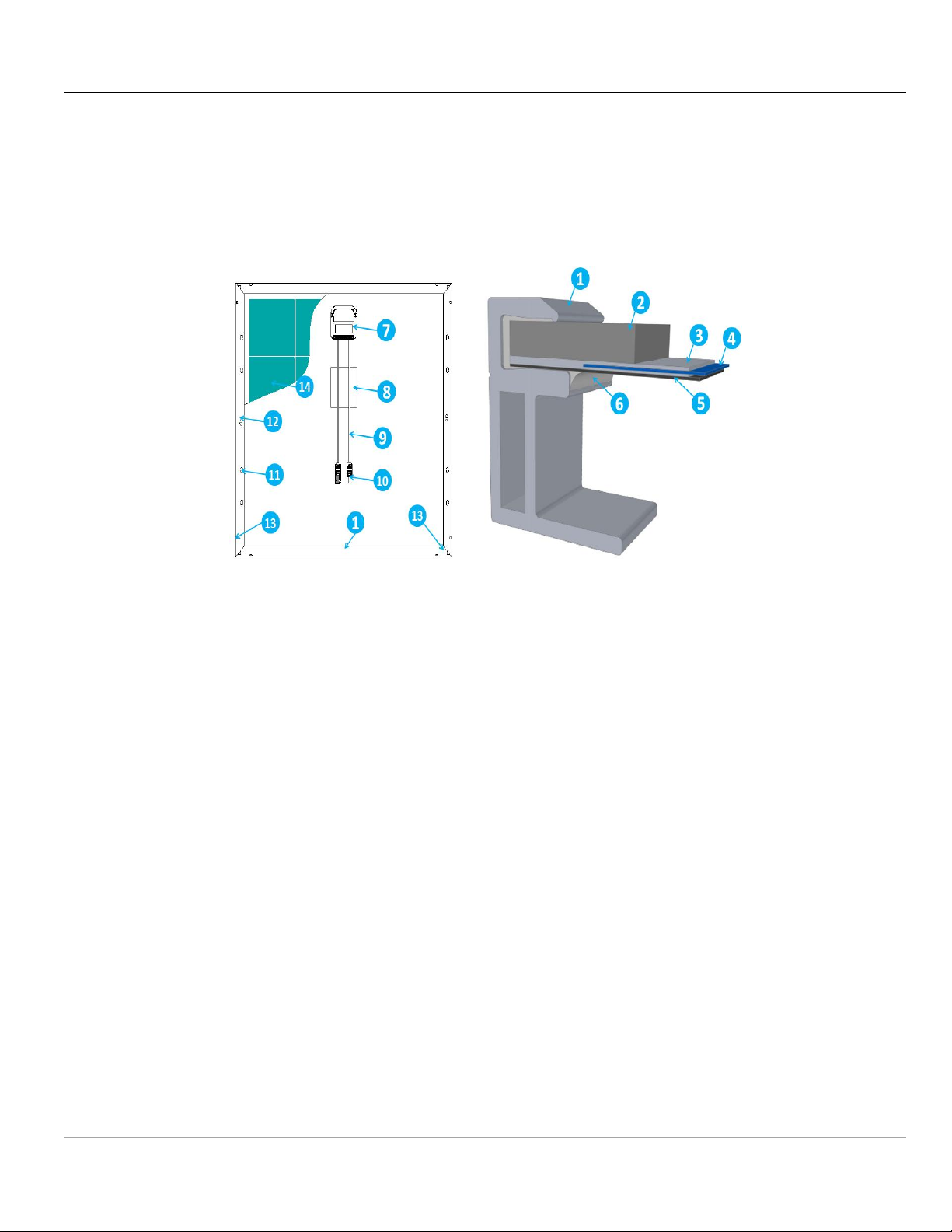
1. Aluminum Frame
2. Glass
3. Encapsulating EVA
4. Cell
5. Backsheet
6. Silicone adhesive
7. Juntion Box
8. Lable
9. Cabel
10.Connector
11.Mounting hole
12.Grounding hole
13.Drainage holes
14.Cell
JA Solar
The mechanical and electrical installation of PV systems should be performed in accordance with all applicable
codes, including electrical codes; building codes and electric utility interconnect requirements. Such requirements
may vary for mounting location, such as building rooftop or motor vehicle applications. Requirements may also vary
with system voltage, and for DC or AC application. Contact local authorities for governing regulations.
th
, 2019
3. Safety Precautions
Figure 1 Modules components and cross-section of the laminated assembly
3.1 Conventional Safety
JA Solar Modules are designed to meet the requirements for the standards IEC 61215-1:2016,
IEC61215-1-1:2016, IEC61215-2:2016, IEC61730-1:2016 and IEC61730-2:2016 that have safety class II according to IEC
61140.The construction meets Class C fire rating for UL790. Rooftop PV systems should only be installed on rooftop
to be capable of handling the additional weighted load of PV system components, including Modules, by a certified
building specialist or engineer and have a formal structure of the complete analysis result.
For your safety, do not attempt to work on a rooftop until safety precautions have been identified and taken,
including without limitation fall protection measures, ladders or stairways, and personal protective equipment.
For your safety, do not install or handle Modules under adverse conditions, including without limitation strong or
gusty winds, and wet or frosted roof surfaces.
3.2 Electrical performance Safety
Photovoltaic Modules can produce DC electricity when exposed to light and therefore can produce an
electrical shock or burn. DC voltage of 30 Volts or higher is potentially lethal.
JA PV Module Installation Manual

Version 1.3 Oct 18
JA Solar
th
, 2019
Modules produce voltage even when not connected to an electrical circuit or load. Please use insulated tools
and rubber gloves when working with Modules in sunlight.
Modules have no on/off switch. Modules can be rendered inoperative only by removing them from sunlight, or
by fully covering their front surface with cloth, cardboard, or other completely opaque material, or by working with
Modules face down on a smooth, flat surface.
In order to avoid arcs and electrical shock, please do not disconnect electrical connections under load. Faulty
connections can also result in arcs and electrical shock. So please keep connectors dry and clean, and ensure that
they are in proper working condition. Never insert metal objects into the connector, or modify them in any way in
order to secure an electrical connection.
Modules can produce higher output than the rated specifications. Industry standard ratings are made at
Standard Test Conditions of 1000 W/㎡ Irradiance, 25°C Cell Temperature and 1.5 Air Mass.
Reflection from snow or water can increase sunlight and therefore boost current and power. In addition, colder
temperatures can substantially increase voltage and power.
If the glass or other material is damaged, please wear personal protection equipment and separated the nodule
from the circuit.
Do not touch the Modules if it’s wet, unless during the cleaning procedure. At the same time the cleaning
operation should according to the manual.
Do not touch the wet connector without protecting yourself with personal protection equipment or rubber gloves.
Do not use mirrors or other magnifiers to concentrate sunlight onto the Modules.
3.3 Operating Safety
Do not open the package of JA Solar Modules until they are ready to be installed during transportation and
storing.
At the same time please protect the package against exposure to damage. Secure pallets from falling over.
Do not exceed the maximum height of pallets to be stacked, as indicated on the pallet packaging.
Store pallets in a cool and dry location until the Modules are ready to be unpackaged.
Please unpack the package of JA Solar Modules according to “JA Solar Modules Un-Pack Instruction”.
Do not lift the Modules by grasping the Modules’ junction box or electrical leads in any condition.
Do not stand or step on the Modules.
Do not drop the Modules on another Module.
Do not place any heavy objects on the Modules to avoid glass breakage.
Be cautious when setting the Modules down on to a surface, especially on the corner of the Modules.
Inappropriate transport and installation may break the Modules.
Do not attempt to disassemble the Modules, and do not remove any attached nameplates or components from
the Modules.
Do not apply paint or adhesive to the Modules top surface.
To avoid damage to the backsheet, do not scratch or hit the backsheet.
Do not drill holes in the frame. This may compromise the frame strength and cause corrosion of the frame.
Do not scratch the anodized coating of the frame (except for grounding connection). It may cause corrosion of
the frame or compromise the frame strength.
Do not attempt to repair the Modules with damaged glass or backsheet.
JA PV Module Installation Manual

Version 1.3 Oct 18
JA Solar
Work only under dry conditions, and use only dry tools. Do not handle Modules when they are wet unless
wearing appropriate protective equipment.
When storing uninstalled Modules outdoor for any period of time, always cover the Modules and ensure that the
glass faces down to stop water from collecting inside the Modules and causing damage to exposed connectors.
th
, 2019
3.4 Fire Safety
Consult your local authority for guidelines and requirements for building or structural fire safety.
Roof constructions and installations may affect the fire safety of building. Improper installation may create
hazards in the event of a fire.
Use appropriate components such as fuses, circuit breaker and grounding connector as requires by local
authority.
Do not use Modules where flammable gasses may be generated.
4. Installation Condition
4.1 Installation position and working environment
JA Solar Modules are intended for use in terrestrial applications only—no outer space marine or vehicle use.
Modules should not be installed nor operated in areas where, salt, hail, snow, sand, dust, air pollution,
chemically active vapors, acid rain, soot, etc., are excessive.
Please adopt appropriate measures to ensure the performance and safety of the Modules when they are
installed or operated in the areas where produces heavy snow, extremely cold, strong wind ,or near the island or
desert where is prone to produce salt fog, or near water.
Modules should be mounted on appropriate mounting structures positioned on suitable buildings, the ground, or
other structures suitable for Modules (e.g. carports, building facades or PV trackers). Modules should not be
mounted on moving vehicles of any kind.
Modules should not be installed in locations where they could be submerged in water.
Modules should be installed in locations where the altitude is less than 2000m
The PV modules of JA Solar are suitable for operation in outdoor non-weather protected locations, exposed to
direct and indirect solar radiation, in an environmental temperature range of at least –40 °C to +40 °C and up to 100 %
relative humidity as well as rain. The temperature limits are defined as the monthly average high and low of the
installation site. Ensure Modules are not subject to wind or snow loads exceeding the maximum permissible loads.
The Modules should be installed in a location where there’s no shading throughout the year. Ensure there’s no
obstacle to block light near the installation site.
Lightning protection is recommended for PV systems that are to be installed in locations with high probability of
lightning strikes.
Do not use Modules near equipment or in locations where flammable gasses may be generated or collected.
JA Solar Modules should not be sited in locations where aggressive substances such as salt or salt-water, or
any other type of corrosive agent, could affect the safety and/or performance of the Modules.
JA Solar Modules have passed the IEC 61701 salt-mist, but galvanic corrosion can occur between the aluminum
frame of the Modules and mounting or grounding hardware if such hardware is comprised of dissimilar metals. JA
JA PV Module Installation Manual

Version 1.3 Oct 18
JA Solar
Solar recommends that only stainless steel and aluminum metal directly contact Modules in seaside installations to
limit corrosion.
th
, 2019
4.1 Tilt Angle Selection
The tilt angle of the Modules is measured between the surface of the Modules and a horizontal ground surface.
The Modules generates maximum power output when it faces the sun directly. Artificially concentrated sunlight shall
not be directed on the module or panel.
In the northern hemisphere, Modules should typically face south, and in the southern hemisphere, Modules
should typically face north.
For detailed information on the best installation angle, please refer to standard solar photovoltaic installation
guides or consult a reputable solar installer or systems integrator.
Because the Modules passed UL 790 class C fire tests, the slope of tested module is 5 in/ft (416 mm/m), which is
the most severe condition. And there is no limited for title angel .
5. Mechanical Installation
5.1 Conventional requirements
Ensure the installation method and supporting system of Modules is strong enough to make the nodules can
withstand all the load conditions. The Installer should provide this guarantee. The installation supporting system
should be tested by the third-party organization with the analysis ability of Static Mechanical, according to the local
national or international standards.
The fire rating of this module is valid only when mounted in the manner specified in the mechanical mounting
instructions. The module is considered to be in compliance with IEC61730-2:2016 only when the module is mounted
in the manner specified by the mounting instructions .Based on standards IEC61730-2:2016 standard, when for the
rooftop mounting, the rooftop covering material should have class C fire resistance at least.
The Modules mounting structure should be made of durable, corrosion-resistant and UV-resistant material.
Modules should be securely attached to the mounting structure.
In regions with heavy snowfall in winter, select the height of the mounting system. So that the lowest edge of the
Modules is not covered by snow for any length of time. In addition, ensure that the lowest portion of the Modules is
placed high enough so that it is not shaded by plants or trees or damaged by flying sand.
When the Modules are supported parallel to the surface of the building wall or roof, a minimum stand-off of 102
mm (4 inches) between the modules and the surface of the wall or the roof is required to allow air to circulate behind
the Modules for heat dissipation. The position of junction box should be on the top side, and away from the ground.
Do not attempt to drill holes in the glass surface and the Modules frames of the Modules as this will void the
warranty.
Before installing Modules on a roof, ensure the roof coverings should have fire resistant Class C. In addition,
any roof penetration required to mount the Modules should be properly sealed to prevent leaks.
Dust building up on the surface of the Modules can impair with Modules performance. JA solar recommends
installing the Modules with a tilt angle of at least 10 degrees, making it easier for dust to be washed off by rain.
Observe the linear thermal expansion of the Modules frames (the recommended minimum distance between two
JA PV Module Installation Manual
Version 1.3 Oct 18
JA Solar
Modules is 1 cm).
Always keep the backsheet of the panel free from foreign objects or structural elements, which could come into
contact with the panel, especially when the panel is under mechanical load.
A module with exposed conductive parts is considered to be in compliance with IEC TS 62548:2013 only when it
is electrically grounded in accordance with the instructions presented below and the requirements of the national
regulations. Any module without a frame (laminate) shall not be considered to comply with the requirements of IEC
61215-1:2016, IEC61215-1-1:2016, IEC61215-2:2016, IEC61730-1:2016 and IEC61730-2:2016 unless the module is
mounted with hardware that has been tested and evaluated with the module under this standard or by a field
Inspection certifying that the installed module complies with the requirements of IEC TS 62548:2013
Metals with the aluminum frame of the Modules that will result in galvanic corrosion. An addendum to IEC 60950-1
Table J.1 that recommends metal combinations not exceeds an electrochemical potential difference of 0.6 Volts.
JA Solar Modules can be mounted in landscape or portrait orientation.
th
, 2019
5.2 Installation methods
Modules can be installed on the frame using mounting holes, clamps. Modules should be installed according to
the following examples. Not mounting the Modules according to these instructions may void the warranty.
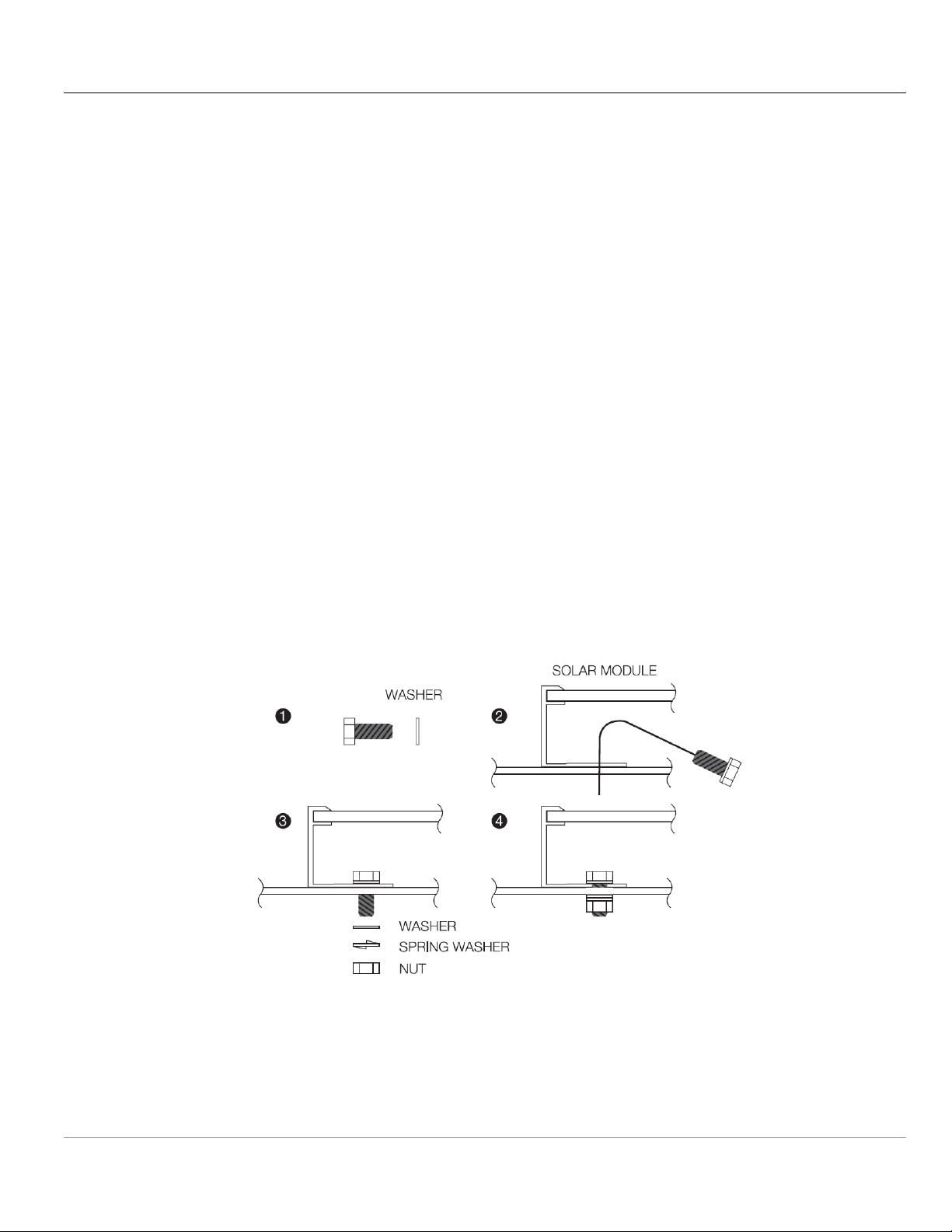
5.2.1 Modules installed with mounting holes
Modules should be bolted to support structures through total 8 mounting holes located in the frame’s back flanges
with positive design load 3600Pa (Safety factor is 1.5)and negative design load 1600Pa(Safety factor is 1.5).
Refer to what is shown in Figure 2 (Mounting Details). Besides, two or more screws or two full threads of a single
screw shall engage the metal.
Figure 2 Mounting Details
For your reference, please use the components specified in below:
1. Bolt 2. Washer
Material: Stainless Steel Material: Stainless Steel
JA PV Module Installation Manual

Version 1.3 Oct 18
JA Solar
Size and Length: M8*16mm Size: M8
3. Spring Washer 4. Nut
Material: Stainless Steel Material: Stainless Steel
Size: M8 Size: M8
Recommended torque is between 14N.m to 20N.m.
th
, 2019
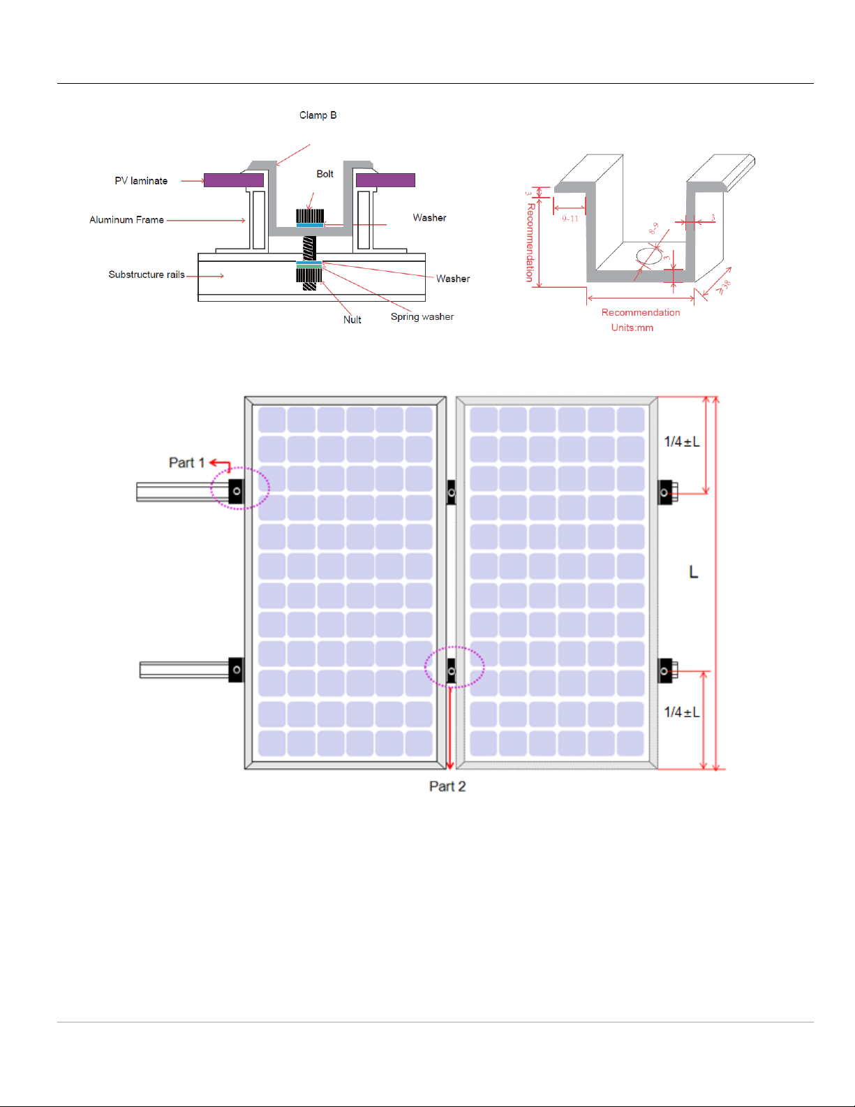
5.2.2 Modules installed with clamp
Modules should be mounted using specialized clamps as shown in Figure 3, Figure 4, Figure 5 and Figure 6.
Remark: Some combinations of the material could be used, regarding the detailed information, please refer to the
listing report.
A) A Module should be attached on a supporting structure rail by metal clamps.
It is recommended to use the clamps under the following condition or approved by system installation:
Size: No less than 38mm) width
Thickness: Following as Clamp A and Clamp B
Material: Aluminum Alloy 6063-T5
Bolt: Stainless Steel ,M8
Nut:Stainless Steel,M8
Washer:Stainless Steel,M8
B) Recommended bolt torque range: 18N.m to 24N.m.
C) The Modules clamps should not contact the front glass or deform the frame in any way. Avoid shading effects
from the Modules clamps. Drainage holes on the Modules frame should not be closed or obscured by the clamps.
Besides, two or more screws or two full threads of a single screw shall engage the metal.
D) This instruction is just used for the 35mm and 40mm height frame
E) This mounting method is designed for positive load 3600Pa (Safety factor is 1.5) or negative load 1600Pa
(Safety factor is 1.5). Only those types which have been qualified could use this method.
F) Mounting method ( showed in Figure 5): a=1/4*L
Figure 3 Clamp A
JA PV Module Installation Manual
Version 1.3 Oct 18
JA Solar
Figure 4 Clamp B
th
, 2019
Figure 5 Mounting instruction 1
JA PV Module Installation Manual
 Loading...