

Shandong USR IOT Technology USR WIFI232 User Manual
USR-WIFI232-B2 User Manual http://www.usriot.com
USR-WIFI232-B2
Embedded WiFi Module User Manual
Version:V6.0.
Note: this article is based on the firmware version for V5.01.01 and above version of the module,
if the version is lower than this version, some function is not supported.
Jinan USR IOT Technology Limited Page 1 of 77 tec@usr.cn

USR-WIFI232-B2 User Manual http://www.usriot.com
Table Of Contents
1 Quick Start.................................................................................................................................................... 6
1.1 Hardware connect............................................................................................................................ 6
1.2 Network connection......................................................................................................................... 7
1.3 communication test.......................................................................................................................... 8
2 Product Overview........................................................................................................................................ 9
2.1 General Description......................................................................................................................... 9
2.2 Device Features............................................................................................................................... 9
2.3 Device Paremeters...........................................................................................................................9
2.4 Key Application...............................................................................................................................10
2.5 Package Information......................................................................................................................11
2.5.1 Recommended Reflow Profile..........................................................................................11
2.5.2 Device Handling Instruction (Module IC SMT Preparation).........................................11
3 Hardware Introduction.............................................................................................................................. 12
3.1 Pins Definition.................................................................................................................................12
3.1.1 USR-WIFI232-B2 Pins Definition.....................................................................................12
3.2 Mechanical Size............................................................................................................................. 13
3.2.1 USR-WIFI232-B2................................................................................................................13
3.3 Antenna............................................................................................................................................14
3.3.1 External Antenna................................................................................................................ 14
3.4 Evaluation Kit..................................................................................................................................14
3.5 Hardware Reference Design........................................................................................................16
3.5.1 Hardware Typical Application........................................................................................... 16
3.5.2 10/100M Ethernet Interface.............................................................................................. 17
3.5.2.1 Ethernet Connection with Transformer................................................................17
3.5.2.2 Ethernet Connection without Transformer..........................................................17
3.5.3 UART Interface....................................................................................................................18
3.5.4 Power Interface...................................................................................................................19
4 Modules Function Description.................................................................................................................19
4.1 User configuration process...........................................................................................................19
4.2 Working mode.................................................................................................................................20
4.2.1 Transparent Mode.............................................................................................................. 20
4.2.2 Serial command mode.......................................................................................................21
4.2.3 GPIO mode..........................................................................................................................22
4.2.4 HTTPD Client mode...........................................................................................................22
4.3 Wireless Networking......................................................................................................................23
4.3.1 STA........................................................................................................................................24
4.3.2 AP..........................................................................................................................................24
4.3.3 AP+STA................................................................................................................................ 25
4.4 Ethernet Interface Communication............................................................................................. 26
4.4.1 USR-WIFI232-B2 Ethernet Interface Networking (As AP).......................................... 26
4.4.2 USR-WIFI232-B2 Ethernet Interface Networking (As STA, N-Ver)........................... 27
4.4.3 USR-WIFI232-B2 Ethernet Interface Networking (As STA, Z-Ver)............................27
4.5 WI-FI parameter setting................................................................................................................ 28
Jinan USR IOT Technology Limited Page 2 of 77 tec@usr.cn

USR-WIFI232-B2 User Manual http://www.usriot.com
4.5.1 Auto- Frequency Function.................................................................................................28
4.5.2 Security.................................................................................................................................28
4.5.3 Search Function for STA................................................................................................... 28
4.5.4 Address Binding..................................................................................................................28
4.6 UART Frame Scheme...................................................................................................................29
4.6.1 UART Free-Frame..............................................................................................................29
4.6.2 UART Auto-Frame.............................................................................................................. 29
4.7 Network Setting..............................................................................................................................29
4.7.1 Socket A............................................................................................................................... 30
4.7.2 Socket B...............................................................................................................................30
4.8 New function................................................................................................................................... 30
TCP password authentication.....................................................................................................30
4.8.1 Registered Package ID/MAC............................................................................................31
4.8.2 Self-adaption Baudrate......................................................................................................31
4.8.3 WEB IO.................................................................................................................................31
4.8.4 Keepalive............................................................................................................................. 32
4.8.5 Multiple STAparameters................................................................................................... 32
4.8.6 Websocket........................................................................................................................... 32
4.8.7 Fast access Wi-Fi(usr-link)............................................................................................... 33
4.9 Palmodic Signal..............................................................................................................................34
4.10 Parameters Configuration.......................................................................................................... 35
4.11 Firmware Upgrade....................................................................................................................... 35
Web Accessing and AT command set.......................................................................................................36
4.12 Configuration via Web Accessing............................................................................................. 36
4.12.1 Open Web Management Interface................................................................................ 36
4.12.2 Quick Configure................................................................................................................37
4.12.3 Mode Selection Page.......................................................................................................37
4.12.4 AP Interface Setting Page...............................................................................................38
4.12.5 STA Interface Setting Page.............................................................................................38
4.12.6 Application Setting Page................................................................................................. 39
4.12.7 Ethernet Setting................................................................................................................40
4.12.8 HTTPD Client Mode.........................................................................................................41
4.12.9 WEB IO.............................................................................................................................. 41
4.12.10 Advanced Page.............................................................................................................. 42
4.12.11 Device Management Page........................................................................................... 42
4.13 AT command Introduction...........................................................................................................43
4.13.1 Configuration Mode..........................................................................................................43
4.13.1.1 Switch to Configuration Mode.............................................................................44
4.13.2 AT+ Instruction Set Overview.........................................................................................44
4.13.2.1 Instruction Syntax Format................................................................................... 46
4.13.2.2 AT+ command Set................................................................................................ 47
4.13.2.2.1 AT+E............................................................................................................ 49
4.13.2.2.2 AT+ENTM....................................................................................................49
4.13.2.2.3 AT+NETP.................................................................................................... 49
Jinan USR IOT Technology Limited Page 3 of 77 tec@usr.cn

USR-WIFI232-B2 User Manual http://www.usriot.com
4.13.2.2.4 AT+UART.................................................................................................... 50
4.13.2.2.5 AT+UARTF..................................................................................................50
4.13.2.2.6 AT+UARTFT...............................................................................................50
4.13.2.2.7 AT+UARTFL............................................................................................... 51
4.13.2.2.8 AT+TMODE................................................................................................ 51
4.13.2.2.9 AT+WMODE...............................................................................................51
4.13.2.2.10 AT+WSKEY.............................................................................................. 52
4.13.2.2.11 AT+WSSSID............................................................................................. 52
4.13.2.2.12 AT+ WSLK................................................................................................ 52
4.13.2.2.13 AT+WEBU.................................................................................................53
4.13.2.2.14 AT+WAP....................................................................................................53
4.13.2.2.15 AT+WAKEY.............................................................................................. 54
4.13.2.2.16 AT+HIDESSID..........................................................................................54
4.13.2.2.17 AT+MSLP..................................................................................................55
4.13.2.2.18 AT+WSCAN..............................................................................................55
4.13.2.2.19 AT+ TCPLK...............................................................................................55
4.13.2.2.20 AT + TCPDIS............................................................................................55
4.13.2.2.21 AT+ WANN................................................................................................56
4.13.2.2.22 AT+ LANN.................................................................................................56
4.13.2.2.23 AT+DHCPDEN.........................................................................................57
4.13.2.2.24 AT+ DHCPGW......................................................................................... 57
4.13.2.2.25 AT+ TCPTO.............................................................................................. 57
4.13.2.2.26 AT+ MAXSK..............................................................................................58
4.13.2.2.27 AT+TCPB..................................................................................................58
4.13.2.2.28 AT+TCPPTB.............................................................................................58
4.13.2.2.29 AT+TCPADDB..........................................................................................59
4.13.2.2.30 AT+TCPTOB.............................................................................................59
4.13.2.2.31 AT+TCPLKB.............................................................................................59
4.13.2.2.32 AT+EPHY..................................................................................................59
4.13.2.2.33 AT+STTC.................................................................................................. 60
4.13.2.2.34 AT+DOMAIN.............................................................................................60
4.13.2.2.35 AT+FUDLX................................................................................................60
4.13.2.2.36 AT+MMID..................................................................................................61
4.13.2.2.37 AT+IDFIR.................................................................................................. 61
4.13.2.2.38 AT+IDEVE.................................................................................................61
4.13.2.2.39 AT+AABR..................................................................................................62
4.13.2.2.40 AT+RELD..................................................................................................62
4.13.2.2.41 AT+Z.......................................................................................................... 62
4.13.2.2.42 AT+MID..................................................................................................... 62
4.13.2.2.43 AT+VER.....................................................................................................62
4.13.2.2.44 AT+H..........................................................................................................62
4.13.2.2.45 AT+ HTTPURL.........................................................................................63
4.13.2.2.46 AT+ HTTPTP............................................................................................63
4.13.2.2.47 AT+ HTTPPH............................................................................................63
Jinan USR IOT Technology Limited Page 4 of 77 tec@usr.cn

USR-WIFI232-B2 User Manual http://www.usriot.com
4.13.2.2.48 AT+ HTTPCN........................................................................................... 63
4.13.2.2.49 AT+ HTTPUA............................................................................................64
4.13.2.2.50 AT+WSSSIDA.......................................................................................... 64
4.13.2.2.51 AT+WSSSIDB.......................................................................................... 64
4.13.2.2.52 AT+WSSSIDC..........................................................................................65
4.13.2.2.53 AT+WSKEYA............................................................................................65
4.13.2.2.54 AT+WSKEYB............................................................................................65
4.13.2.2.55 AT+WSKEYC........................................................................................... 66
4.13.2.2.56 AT+ WSQY............................................................................................... 67
4.13.2.2.57 AT+ HTPMODE....................................................................................... 67
4.13.2.2.58 AT+ HTPSV.............................................................................................. 67
4.13.2.2.59 AT+ HTPTP.............................................................................................. 67
4.13.2.2.60 AT+ HTPURL............................................................................................68
4.13.2.2.61 AT+ HTPHEAD........................................................................................ 68
4.13.2.2.62 AT+ REGEN............................................................................................. 68
4.13.2.2.63 AT+ REGTCP...........................................................................................69
4.13.2.2.64 AT+ REGID...............................................................................................69
5 USR-WIFI232-A/B/C Usage Introduction..............................................................................................69
5.1 Module Debug................................................................................................................................ 69
5.1.1 Software Debug Tools........................................................................................................69
5.1.2 Network Connection...........................................................................................................70
5.1.3 Debug................................................................................................................................... 70
5.2 Use Cases.......................................................................................................................................72
5.2.1 Wireless Control Application.............................................................................................72
5.2.2 Remote Management Application....................................................................................73
5.2.3 Transparent Serial Port Application.................................................................................73
5.2.4 Wireless Data Acquisition Card Application...................................................................74
Appendix B: Disclaimer................................................................................................................................76
Appendix C: History......................................................................................................................................76
Jinan USR IOT Technology Limited Page 5 of 77 tec@usr.cn
USR-WIFI232-B2 User Manual http://www.usriot.com
1 Quick Start
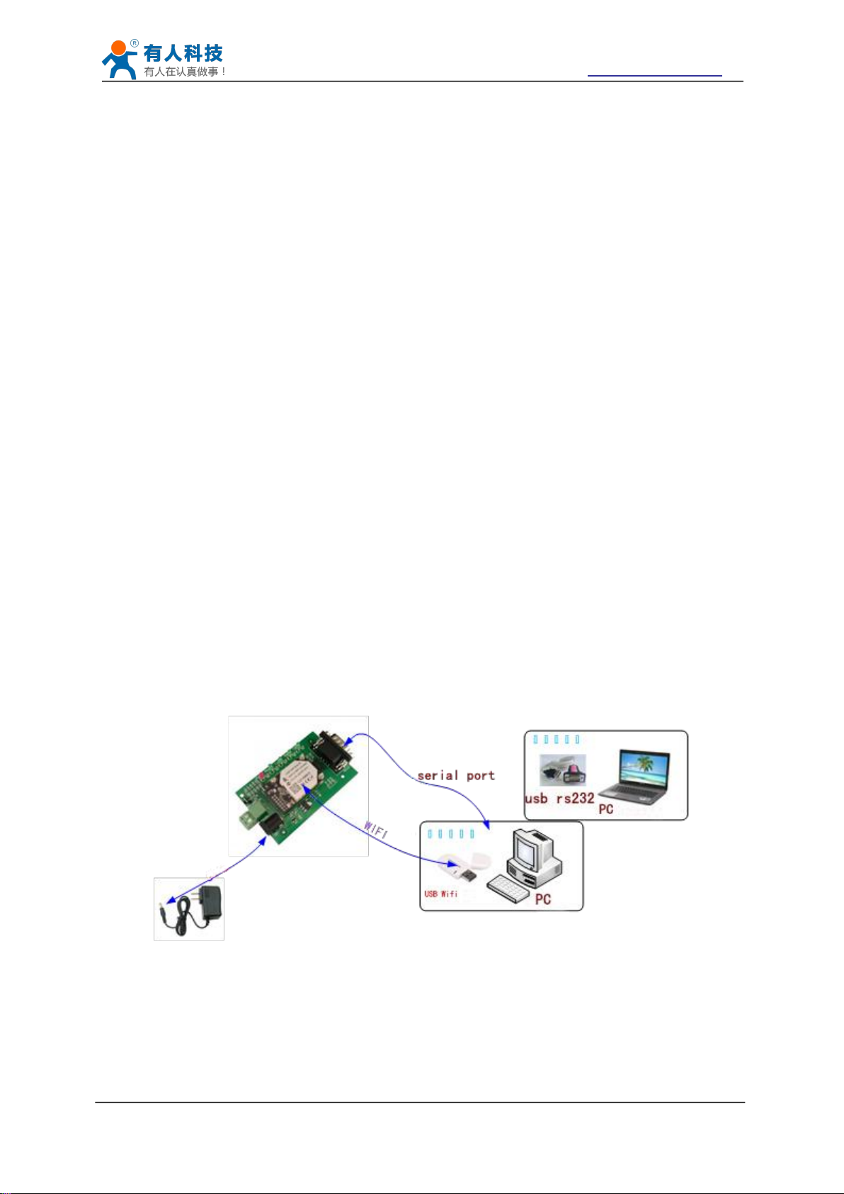
1.1 Hardware connect
Figure 1 hardware connection diagram
USR-WIFI232 series product is used to transmit data between RS232 and WIFI TCPIP
transparently, user can update the product to WIFI control without knowing the WIFI and TCPIP
detail. All the convert work is done by the module. For users, the RS232 side is only as a serial
device,the WIFI side is TCPIP Socket data. User can setup the work detail by sample settings
which can setup via inside web pages or RS232 port. The setup work only need do once, then it
will save the setting forever.
This chapter is a user guide for USR-WIFI232 series products. We suggest users follow the guide
to test module at first, and will have a good understanding of the modules. Users can also choose
the chapter which you are interested in to read. For specific details and instructions, please refer
to the following chapters.
If there are problems in using the process, you can refer to the official website of our application
case:
http://www.usriot.com/Faq/cat-47.html
We can also submit the issue to our customer support center:
http://h.usriot.com
In order to test WIFI module, we need connect module RS232 to PC and also WIFI to PC.
In order to test the communication between serial and WIFI network, we need to connect the
serial port to PC, and also connect WIFI networks to PC. Due to the special need both WIFI and
serial, we use PC which add USB WIFI network Card such as the following picture.
About the serial connection, because the module RS232 is 3.3V TTL level, the computer can not
connect to module directly, the user needs to have a TTL to RS232 adapter cable and then
connect to the computer. in order to facilitate the test, we provide USR-WIFI232-B2 evaluation
board for users to choose.
Jinan USR IOT Technology Limited Page 6 of 77 tec@usr.cn
USR-WIFI232-B2 User Manual http://www.usriot.com
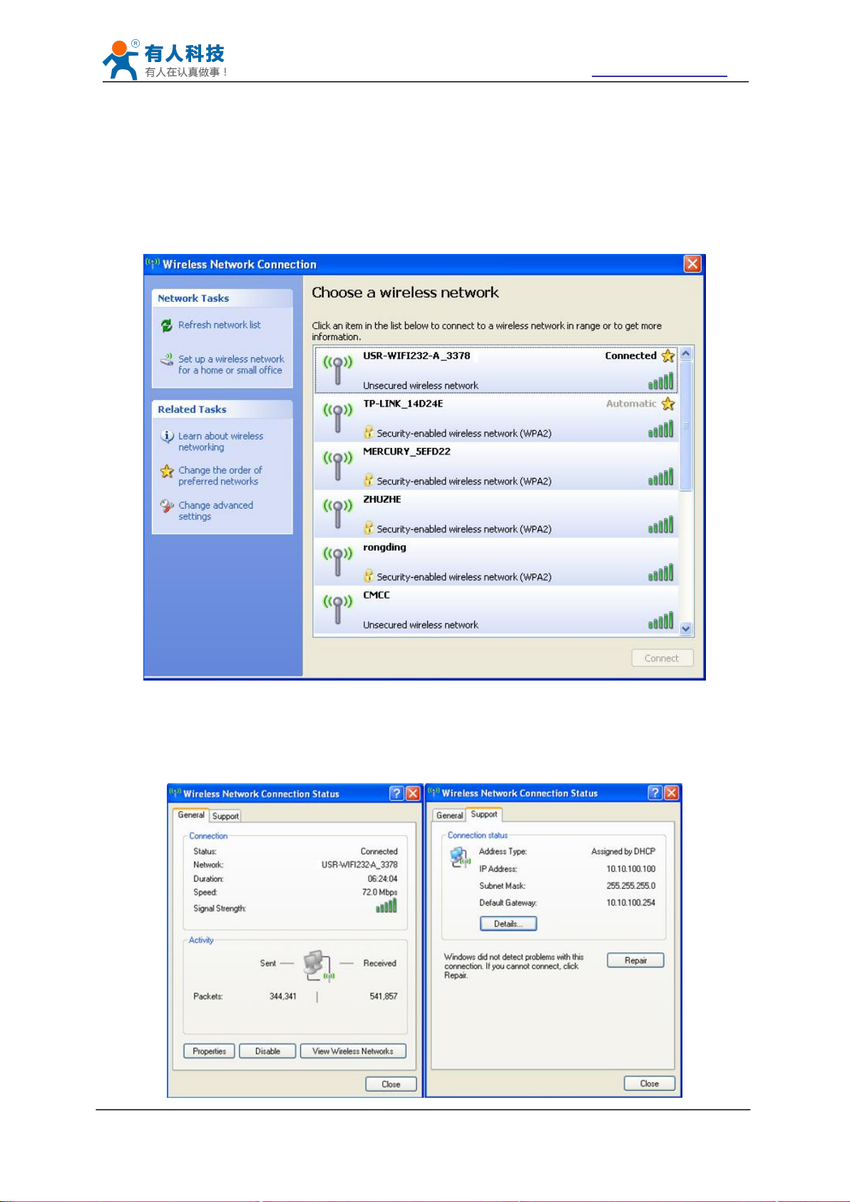
1.2 Network connection
Figure 2 WIFI Search
The following is the USR-WIFI232-B2 module example,Other modules are the same.Open Wi-Fi,
search network, as shown in below, USR-WIFI232-B2_3378(B determined according to the
specific type of module, XXXX is the MAC address after the four) is the default network name
(SSID) of the module.
Join the network, choose to automatically obtain IP, WIFI module supports DHCP Server feature
and is enabled by default.
Jinan USR IOT Technology Limited Page 7 of 77 tec@usr.cn
USR-WIFI232-B2 User Manual http://www.usriot.com
Figure 3 WIFI connection
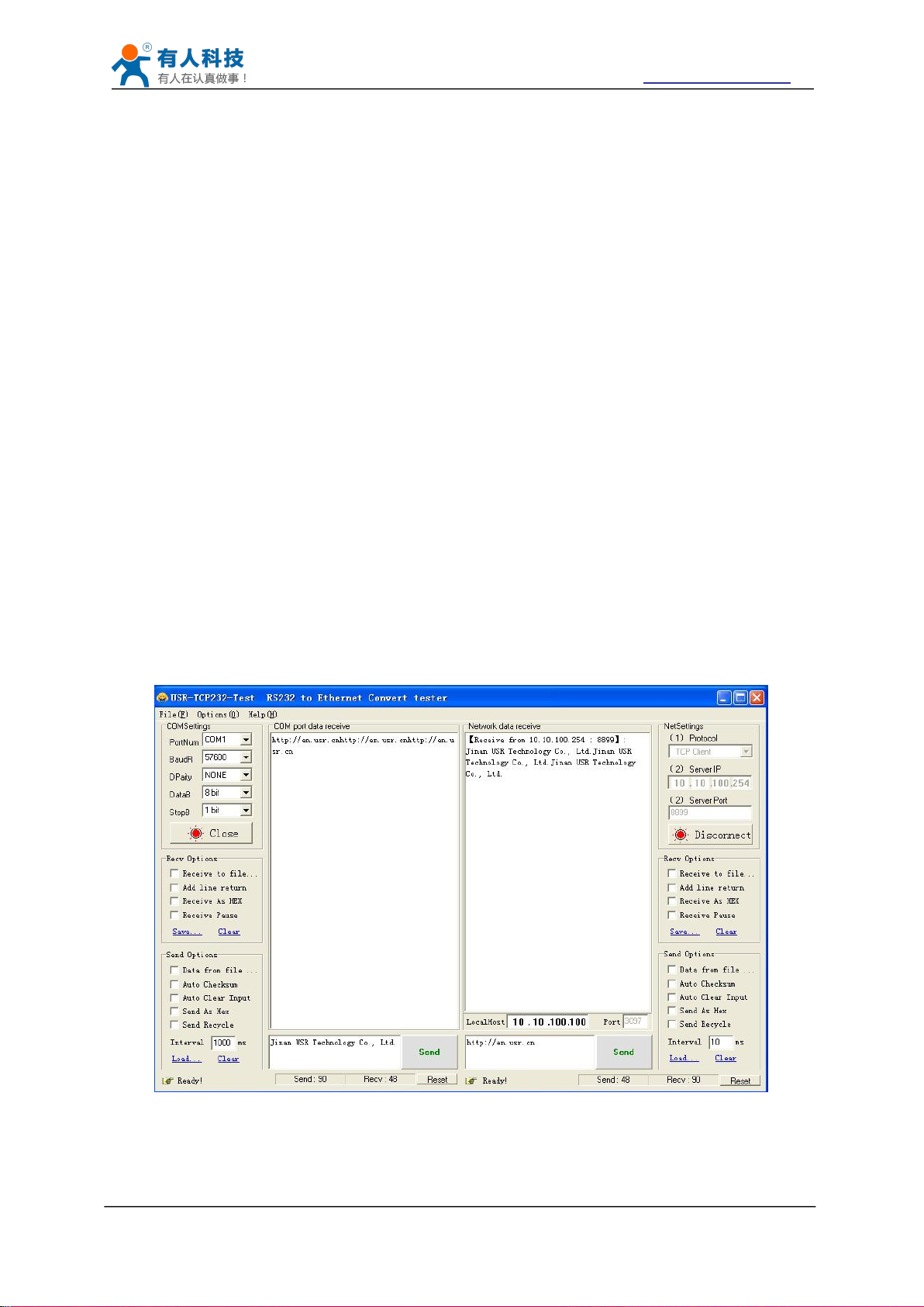
1.3 communication test
SSID:USR-WIFI232-B2;
Encryption mode:open,none;
UART:57600,8,1,None;
Network parameters:TCP,Server,8899,10.10.100.254;
IP:10.10.100.254;
1. Open test software USR-TCP232-Test;
2. COM Settings area (left):
3. Net Settings area (right):
Figure 4 serial / network transmission test
Now, nlink led of USR-WIFI232-B2 Evaluation Board is lighting.
Module’s default setting:
We just need to follow the parameters of the corresponding set of network communication
parameters, you can make serial <--> WIFI communication, the steps are as follows:
Choose COM port witch has connect the module, there is COM3, choose band rate to 57600, this
is the default band rate of WIFI module, Click Open COM port.
Choose TCP client mode, Server IP write 10.10.100.254, it is the WIFI default IP address, Server
port to 8899, It is the default Port the WIFI module listen, Click Connect to link to the module.
Now, you can test send data between RS232 and WIFI.
COM port to WIFI: PC RS232 -> Module RS232 -> Module WIFI -> PC WIFI.
WIFI to COM port: PC WIFI -> Module WIFI -> Module RS232 -> PC RS232.
Jinan USR IOT Technology Limited Page 8 of 77 tec@usr.cn

USR-WIFI232-B2 User Manual http://www.usriot.com
2 Product Overview
2.1 General Description
2.2 Device Features
Support IEEE802.11b/g/n Wireless Standards
Support TCP/IP/UDP Network Protocols
Support UART/GPIO/Ethernet Data Interface
Support Work As STA/AP/AP+STA Mode
Support Router/Bridge Mode Networking
Support External Antenna(max 280m)
Support Transparent Transmission Mode
Support AT+ Instruction Set for Configuration
Support Friendly Web Configuration Page
Support Palmodic Signal
Support UART Auto-Frame Function
Single +3.3V Power Supply
FCC/CE Certificated
Support customization
2.3 Device Paremeters
Table 1 USR-WIFI232-B2 Module Technical Specifications
USR-WIFI232-B2 module is an integration of 802.11 b/g/n wi-fi module,which provide a wireless
interface to any equipment with a Serial interface for data transfer.
The module used to MAC, baseband chip, RF transceiver unit, as well as the power
amplifier;Embedded firmware support wi-fi protocols and configuration, as well as the network
TCP/IP protocol stack.
USR-WIFI232-B2 uses the industry's highest performance embedded industrial structure, and for
the application of smart furniture, smart grid, handheld devices, personal medical, industrial
control, etc. These data fields, do a professional optimization.
USR-WIFI232-B2 as a hot spot can accommodate 32 clients simultaneously wi-fi access, but also
can accommodate 32 TCP client.
Jinan USR IOT Technology Limited Page 9 of 77 tec@usr.cn
USR-WIFI232-B2 User Manual http://www.usriot.com
2.4 Key Application
Remote equipment monitoring
Industrial sensors and controls
Asset tracking and telemetry
Home automation
Medical devices
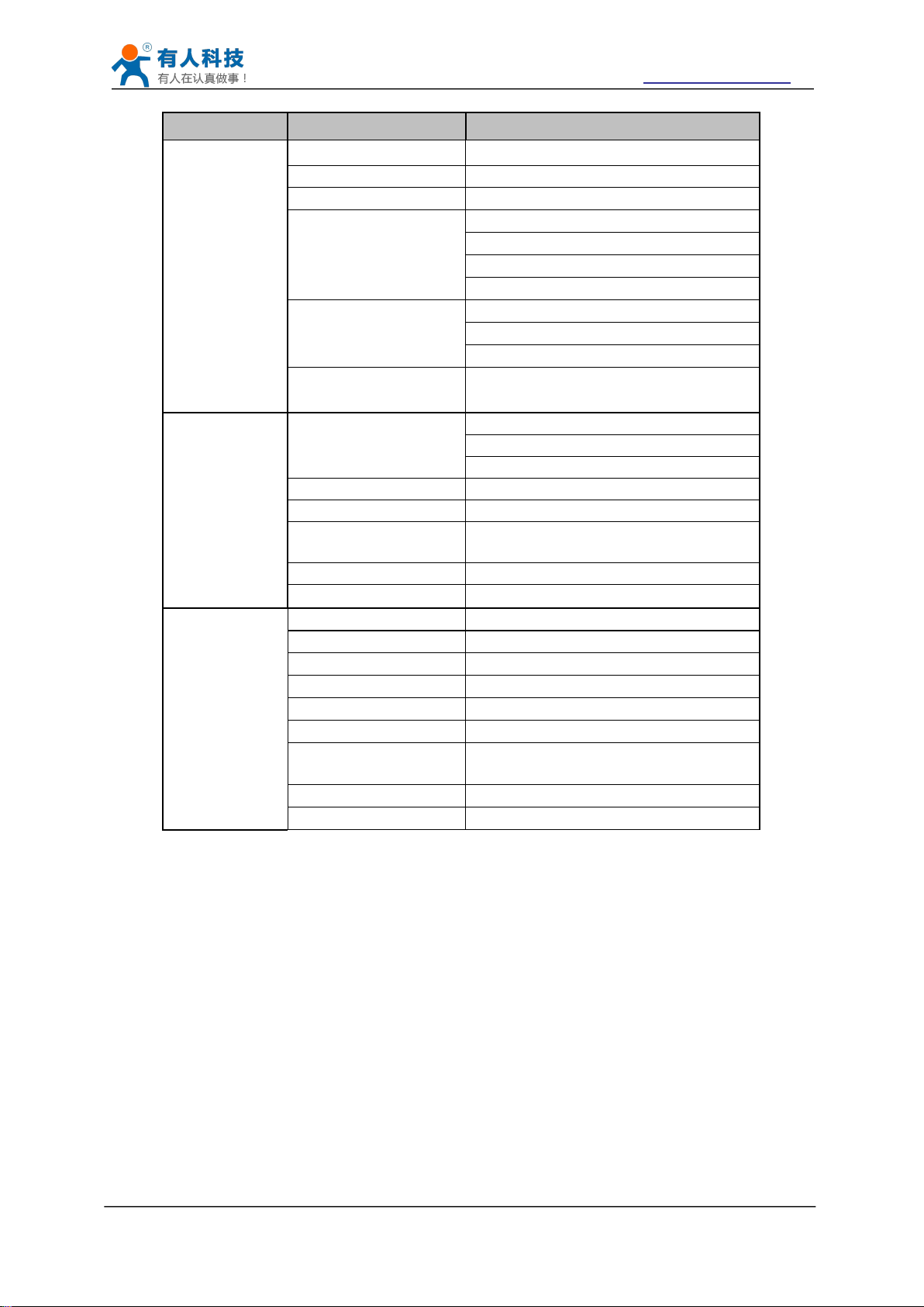
Class Item Parameters
Certification FCC/CE
Wireless standard 802.11 b/g/n
Frequency range 2.412GHz-2.462GHz
802.11b: +20 dBm (Max.)
802.11g: +18 dBm (Max.)
802.11n: +15 dBm (Max.)
Configurable
802.11b: -89 dBm
802.11g: -81dBm
802.11n: -71dBm
UART: 300bps - 460800bps
GPIOs
Ethernet: 100Mpbs
-40℃- 85℃
-40℃- 125℃
Wireless
Parameters
Hardware
Parameters
Transmit Power
Receiver Sensitivity
Antenna Option External:I-PEX Connector
Data Interface
Operating Voltage 3.3V (+/-5%)
Operating Current 170mA~300mA
Operating
Temperature
Storage Temperature
Dimensions and Size 25×40×8mm
Network Type Station /AP mode/STA+AP
Software
Parameters
Security Mechanisms WEP/WAP-PSK/WAP2-PSK
Encryption WEP64/WEP128/TKIP/AES
Work Mode Transparent Mode/Serial command
AT command AT+instruction set
Network Protocol
Max. TCP Connection 32
User Configuration
TCP/UDP/ARP/ICMP/DHCP/DNS/HT
TP
Web Server+AT command config.
Jinan USR IOT Technology Limited Page 10 of 77 tec@usr.cn
USR-WIFI232-B2 User Manual http://www.usriot.com
2.5 Package Information
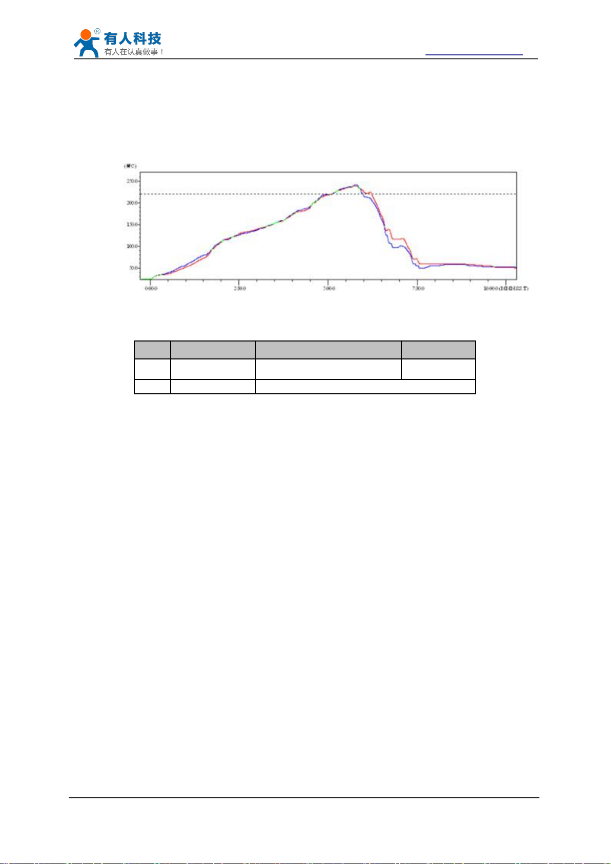
2.5.1 Recommended Reflow Profile
Figure 5 Reflow Soldering Profile
Table 2 Reflow Soldering Parameter
2.5.2 Device Handling Instruction (Module IC SMT Preparation)
Shelf life in sealed bag: 12 months, at <30℃ and <60% relative humidity (RH)
After bag is opened, devices that will be re-baked required after last baked with window time
Recommend to oven bake with N2 supplied.
Baked required with 24 hours at 125 ± 5℃ before rework process for two modules, one is
Recommend to store at ≦10% RH with vacuum packing.
If SMT process needs twice reflow:
NO.
Item
Temperature (Degree)
Time(Sec)
1
Reflow Time
Time of above 220
35~55 sec
2
Peak-Temp
260 max
Note:
1. Recommend to supply N2 for reflow oven.
2. N2 atmosphere during reflow (O2<300ppm).
168 hours.
new module and two is board with module.
(1) Top side SMT and reflow (2) Bottom side SMT and reflow
Case 1: Wifi module mounted on top side. Need to bake when bottom side process over 168
hours window time, no need to bake within 168 hours.
Case 2: Wifi module mounted on bottom side, follow normal bake rule before process.
Note:
Window time means from last bake end to next reflow start that has 168 hours space.
Jinan USR IOT Technology Limited Page 11 of 77 tec@usr.cn
USR-WIFI232-B2 User Manual http://www.usriot.com
3 Hardware Introduction
3.1 Pins Definition
3.1.1 USR-WIFI232-B2 Pins Definition
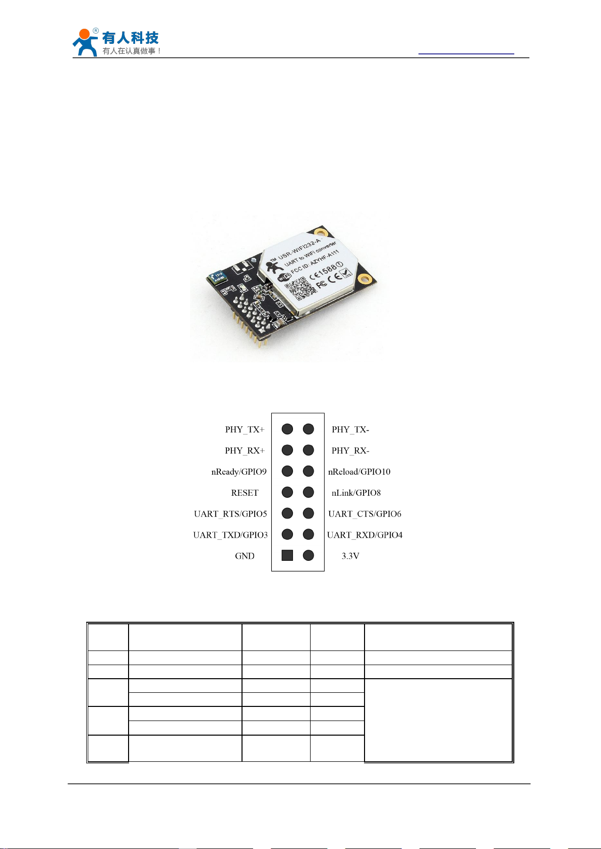
Figure 6 USR-WIFI232-B2
Figure 7 USR-WIFI232-B2 Pins Map
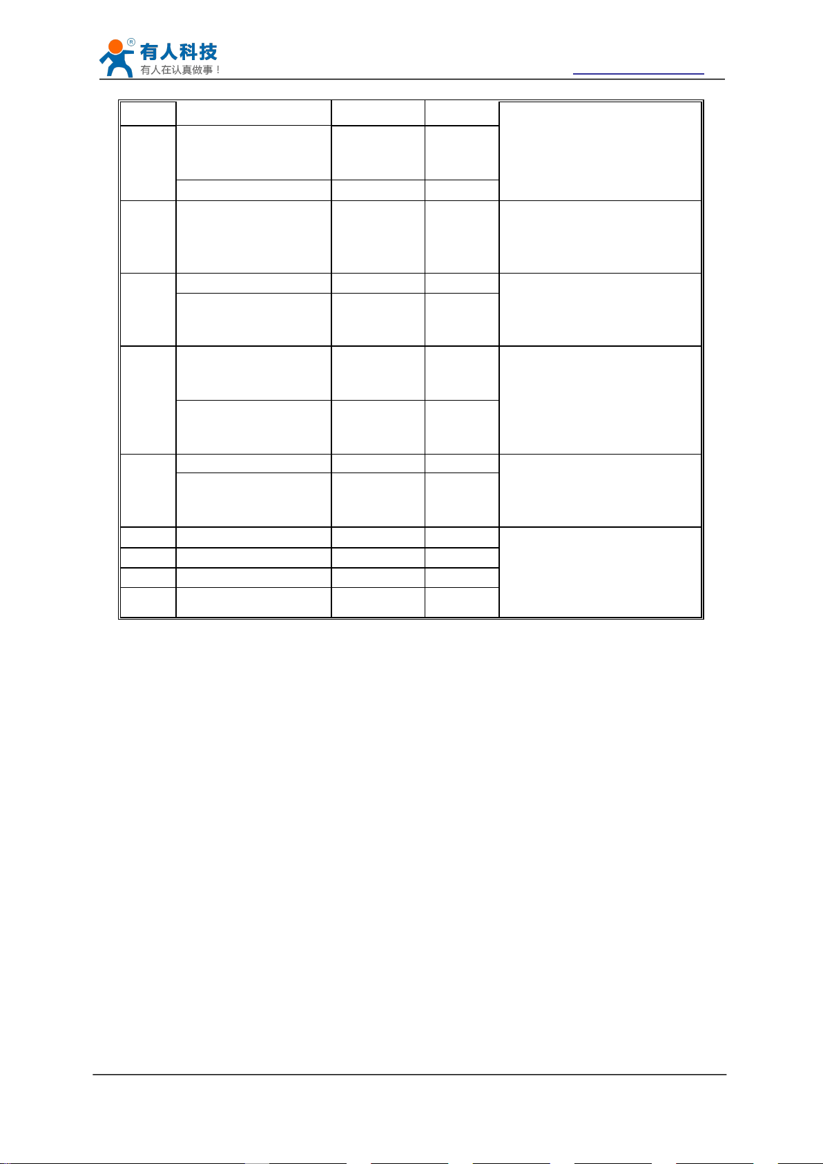
Table 3 USR-WIFI232-B2 Pins Definition
Pin
Description
Name
Directio
n
Note
1
Ground--GND
GND
Power
Ground
2
VCC 3.3V@350mA
3.3V
Power
3.3V @ 350mA power input
3
UART Data Transmit
UART_TXD
O
If not use UART function,
this 4 pins can be configured
as GPIO pins, and can
change GPIO pin status
through AT command
GPIO
GPIO3
I/O
4
UART Data Receive
UART_RXD
I
GPIO
GPIO4
I/O
5
UART sends request
of data transmission
UART_RTS
O
Jinan USR IOT Technology Limited Page 12 of 77 tec@usr.cn
USR-WIFI232-B2 User Manual http://www.usriot.com
GPIO
GPIO5
I/O
6
UART receives data
transmission
permission
UART_CTS
I
GPIO
GPIO6
I/O
7
Module reset signal
RESET
I
“Low ( 0 )” effective reset
input.
The reset duration should be
kept more than 300ms
8
WiFi status Indication
nLink
O
“0”- WIFI connection
available
“1”- No WIFI connection
Can be configured as GPIO.
GPIO
GPIO8
I/O
9
Indicate the module
status of power on
process
nReady
O
“0” or “Palmodic Signal” -
Finish module boot up
process;
“1” - Module boot up not
finish.
Can be configured as GPIO.
GPIO
GPIO9
I/O
10
Restore configuration
nReload
I
Module will Restore factory
default configuration after set
this pin “0” more than 1s,
then set “1”.
GPIO
GPIO10
I/O
11
Ethernet Input+
PHY_RX+
I
+1.8V Ethernet Data
Interface
Support transformer and
direct connection (AC
couple) mode.
12
Ethernet Input-
PHY_RX-
I
13
Ethernet Output+
PHY_TX+
O
14
Ethernet Output-
PHY_TX-
O
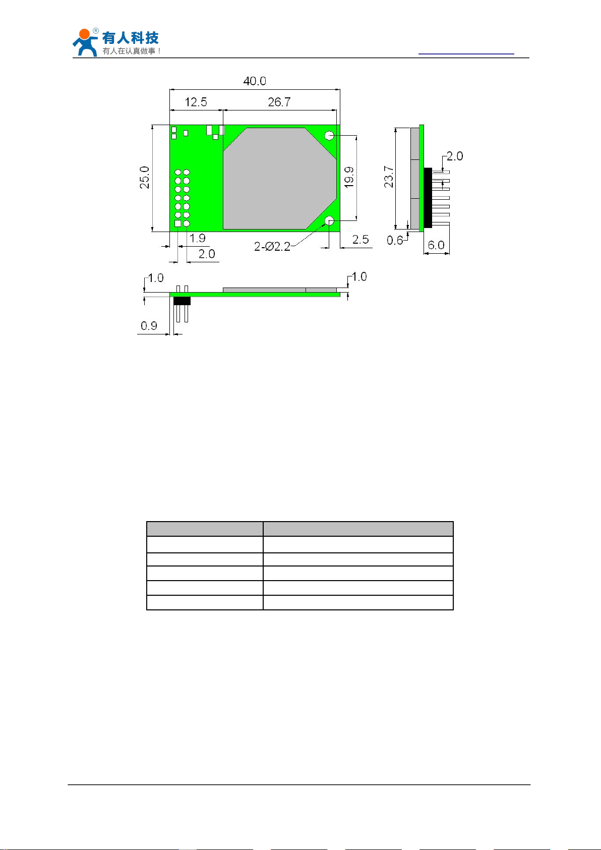
3.2 Mechanical Size
3.2.1 USR-WIFI232-B2
USR-WIFI232-B2 modules physical size (25x40mm) as follows:
USR-WIFI232-B2 module Mechanical Size:
Jinan USR IOT Technology Limited Page 13 of 77 tec@usr.cn
USR-WIFI232-B2 User Manual http://www.usriot.com
Figure 8 USR-WIFI232-B2 Mechanical Size
3.3 Antenna
3.3.1 External Antenna
Table 4 USR-WIFI232-B2 External Antenna Parameters
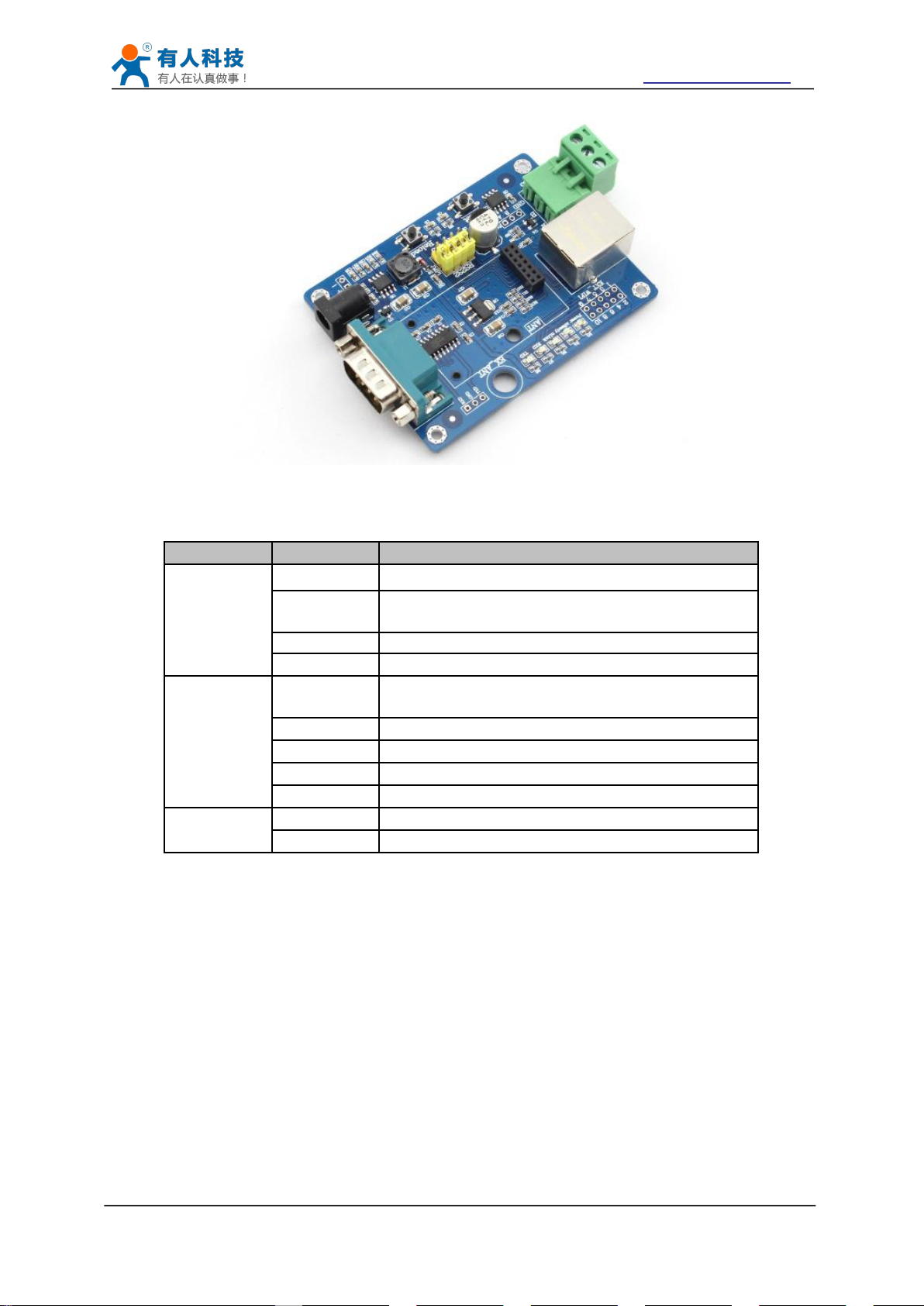
3.4 Evaluation Kit
Item
Parameters
Frequency range
2.4~2.5GHz
Impedance
50 Ohm
VSWR
2 (Max)
Return Loss
-10dB (Max)
Connector Type
I-PEX or populate directly
USR-WIFI232-B2 modules support external antenna,USR-WIFI232-B2 modules must be
connected to the 2.4G antenna according to IEEE 802.11b/g/n standards.
The antenna parameters required as follows:
USR provides the evaluation kit to promote user to familiar the product and develop the detailed
application. The evaluation kit shown as below, user can connect to USR-WIFI232-B2 module
with the RS-232 UART port, 100M Eth port or Wireless port to configure the parameters, manage
the module or do the some functional tests.
Jinan USR IOT Technology Limited Page 14 of 77 tec@usr.cn
USR-WIFI232-B2 User Manual http://www.usriot.com
Figure 9 USR-WIFI232-A/B module Evaluation Kit
Table 5 USR-WIFI232-A/B Evaluation Kit Interface Description
Function
Name
Description
External
Interface
DC jack
5V power input connector
DB9
Male serial jack of 9-pin,and used to connect to
PC
RJ-45
100M Eth Interface
Module
2x7 2mm DIP connector, connect WIFI module
LED
Power
(Red)
3.3V Power Indicator
TXD
TXD Indicator
RXD
RXD Indicator
Ready
nReady/GPIO Indicator
Link
nLink/GPIO Indicator
Button
Reset
Used to reset the module.
Reload
Module restore to factory default configuration.
Jinan USR IOT Technology Limited Page 15 of 77 tec@usr.cn
USR-WIFI232-B2 User Manual http://www.usriot.com
3.5 Hardware Reference Design
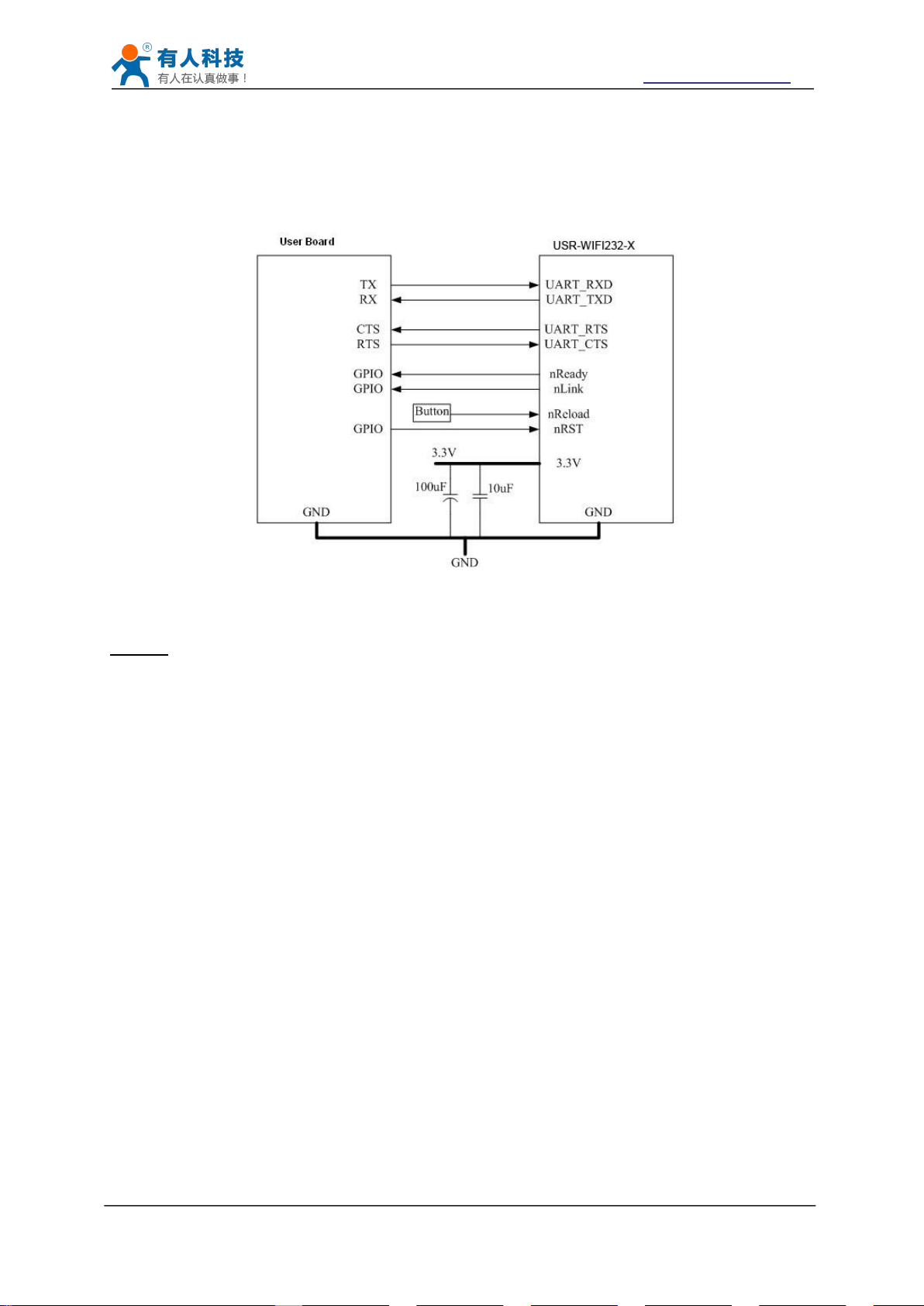
3.5.1 Hardware Typical Application
Figure 10 USR-WIFI232-B2 Hardware Typical Application
Notes:
nRST- Module hardware reset signal. Input. Logics “0” effective.
There is 100K Ohm pull-up resister internal up to 3.3V. When module power up or some issue
happened, MCU need assert nRST signal “0” at least 300ms, then set” 1” to keep module fully
reset.
nReady- Module boot up ready signal. Output. Logics “0” effective.
There is 4.7K Ohm pull-up resister internal up to 3.3V. The module will output “0” “or “Palmodic
Signal” after normal boot up. This signal used to judge if module finish boot up and ready for
application or working at normal mode.
nLink- Module WIFI connection indication. Output.
There is 4.7K Ohm pull-up resister internal up to 3.3V. When module connect to AP (STA mode)
or some WiFi STA connect to module (AP mode), the module will output “0”. This signal used to
judge if module already at WiFi connection status.
nReload- Module restore to factory default configuration.Input. Logics “0” effective.
User can assert nReload signal “0” more than 3’s through button or MCU pin, then release,
module will restore to factory default configuration and re-start boot up process. User need add
4.7K~10K Ohm pull-up resister external the module.
UART_TXD/RXD- UART port data transmit and receive signal.
There is 1K Ohm pull-down resister internal. User can’t add pull-up resister at these pins.
Jinan USR IOT Technology Limited Page 16 of 77 tec@usr.cn
USR-WIFI232-B2 User Manual http://www.usriot.com
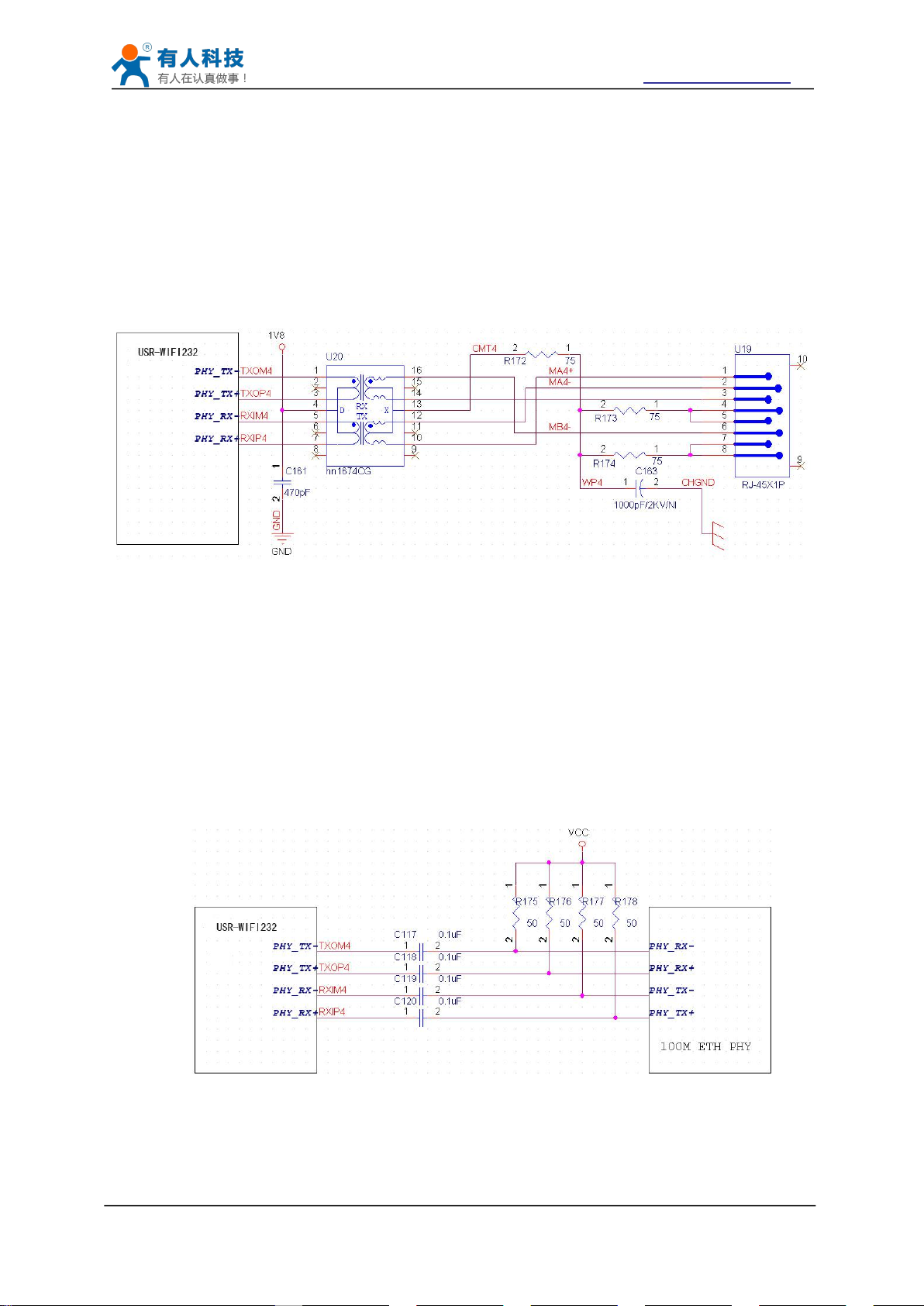
3.5.2 10/100M Ethernet Interface
3.5.2.1 Ethernet Connection with Transformer
Figure 11 Ethernet Reference Design with Transformer
3.5.2.2 Ethernet Connection without Transformer
Figure 12 Ethernet Reference Design without Transformer
USR-WIFI232-A/B/C modules provide one 10/100M Ethernet PHY layer interface for data
transition or user configuration. This Ethernet support with transformer and without transformer
(PHY-to-PHY) 2 kinds of connection.
User board put Ethernet transformer and RJ-45 connector. This is a general 10/100M Ethernet
phy layer connection. The reference design as following:
(Above is for USR-WIFI232-B2 pin type module)
For this application, Ethernet will work as internal data transmition interface and save one
transformer and RJ45 connector. Ethernet PHY-to-PHY connection will use AC coupled
connection. This is a space and cost optimized solution. Hardware reference design as following:
Note: VCC signal at reference design shall base on user board PHY chipset voltage level, such
as 2.5V power supply for general Ethernet PHY chipset.
(Above is for USR-WIFI232-B2 pin type module)
Jinan USR IOT Technology Limited Page 17 of 77 tec@usr.cn
USR-WIFI232-B2 User Manual http://www.usriot.com
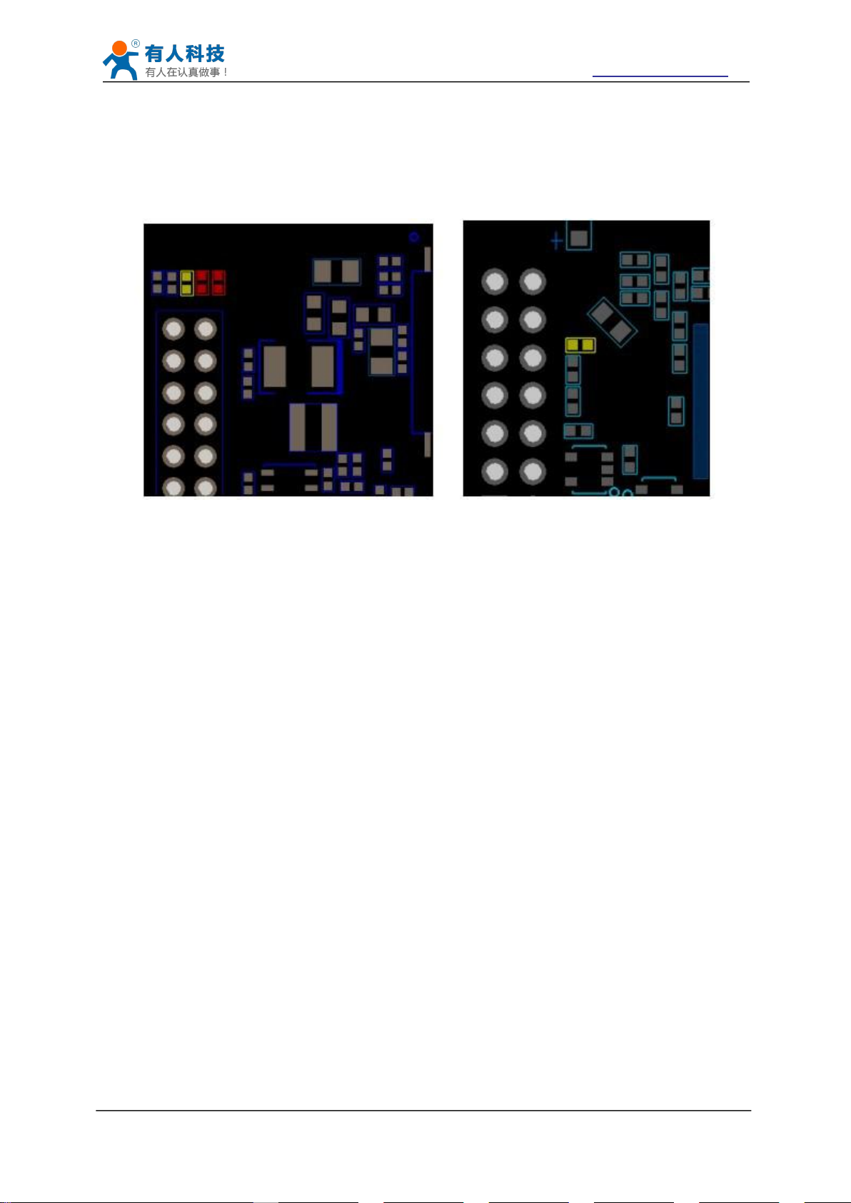
1. Weld 0 ohm resistance in red position
2. Remove the component in yellow position
Figure 13 Schematic resistance changes
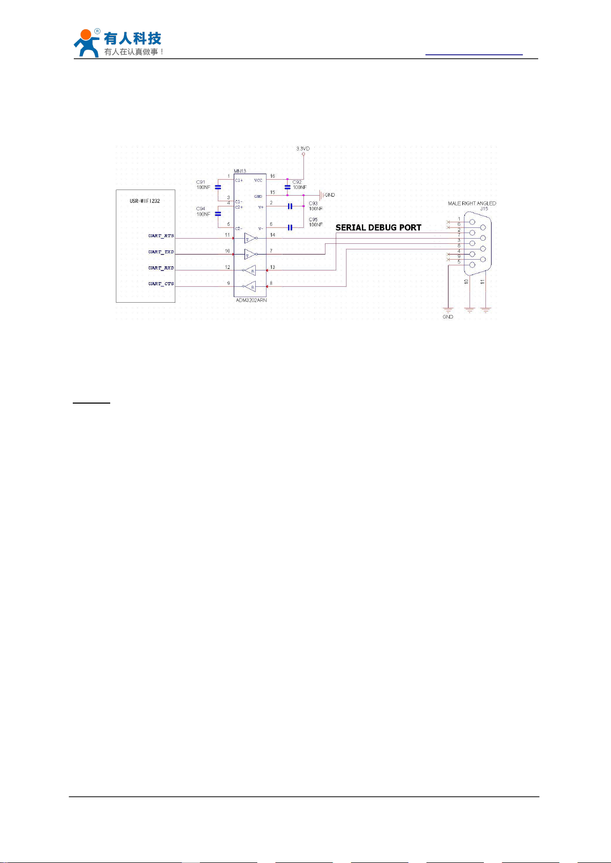
3.5.3 UART Interface
This module Ethernet interface default is for the application with transformer connection. If you
need PHY-PHY directly connection, please change the hardware as follows:
BOT side component TOP side component
Specific PHY-PHY direct connection reference to user manual chapter 1.3.2.2 application of
Ethernet without transformer and AT+FEPTP command
The command:
AT+FVEW=enable<CR> to open ethernet WAN port function
Remark:
1. Only when ethernet as WAN, this command is needed. Module default LAN port.
2. After this command, make sure module WAN IP and LAN IP in different segment. (Modify the
ALN IP in AP Settings, modify the WAN IP in STA Settings)
AT+FEPTP=on<CR> Quey/set default ethernet PHY-PHY on/off
AT+FEPHY=on<CR> Open ethernet function permanently
AT+RELD<CR> Command with “F” need to be affective after AT+RELD
After module reset, command effect, then will not impact by Reload
For user’s design, pls note:
1. Cable connection should be AC coupling, your cable need be pulled up to VCC (fit with PHY
chip level)
2. Cable TX connected to RX. In PHY-PHY direct connection, PHY chip dose not support
direct/ cross self-adaption
3.Your PHY chip on board should better to be forced into 100M work mode
UART interface is the serial data transmition interface mainly used for USR-WIFI232-B2 modules.
Jinan USR IOT Technology Limited Page 18 of 77 tec@usr.cn
USR-WIFI232-B2 User Manual http://www.usriot.com
Figure 14 Figure 10 UART Interface Reference Design
3.5.4 Power Interface
4 Modules Function Description
4.1 User configuration process
User can add RS-232 chipset on user board and convert the signal to RS-232 voltage to
communicate with outside equipment or sensors. USR-WIFI232-B2 modules UART interface
include 4 general signals: TXD/RXD/RTS/CTS. The hardware reference design with RS-232
chipset as following:
Notes: TXD pin is also hardware configuration pin internal module. So this pin MUST pull-down
during module power up. USR-WIFI232-B2 modules provide internal pull-down resister, user can’t
add pull-up/pull-down resister on user board, which may cause module can’t work.
USR-WIFI232-B2 module support single +3.3V power supply. The peak current shall about
350mA and normal WiFi working current shall about 200mA. The power save (WiFi OFF) mode
will about 100mA
Decoupling at power pin suggested, At least one 100uF and one 10uF capacitor required at user
board and put near module power input pin will increase the reliability and performance.
After USR-WIFI232-B2 module electric starter, based on user pre-set parameters, automatically
connect to wireless networks and servers, and enter the working mode is set to open in
accordance with the default serial port parameters.
The parameters which need to configure include:
Jinan USR IOT Technology Limited Page 19 of 77 tec@usr.cn

USR-WIFI232-B2 User Manual http://www.usriot.com
Wireless Network Parameters
Wireless Network Name(SSID)
Security Mode
Encryption Key
TCP/UDP Linking Parameters
Protocol Type
Link Type(Server or Client)
Target Port ID Number
Target Port IP Address
Serial Port Parameters
Baud Rate
Data Bit
Parity (Check) Bit
Stop Bit
Hardware Flow Control
Work Mode Selection
Transparent mode/Serial command mode/GPIO mode
4.2 Working mode
4.2.1 Transparent Mode
The following sections will introduce specific to each part in detail.
USR-WIFI232-B2 modules support serial interface transparent transmission mode. The benefit of
this mode is achieves a plug and play serial data port, and reduces user complexity furthest. In
this mode, user should only configure the necessary parameters. After power on, module can
automatically connect to the default wireless network and server.
As in this mode, the module's serial port always work in the transparent transmission mode, so
users only need to think of it as a virtual serial cable, and send and receive data as using a
simple serial. In other words, the serial cable of users’ original serial devices is directly replaced
with the module; user devices can be easy for wireless data transmission without any changes.
The transparent transmission mode can fully compatible with user’s original software platform
and reduce the software development effort for integrate wireless data transmission.
Notes: Users also open the serial port hardware flow control (CTS/RTS) function, so that we can
make the bit error rate to a minimum.If the user doesn't need hardware flow control function of the
serial port, only need to the corresponding pin foot (CTS/RTS) hung up.
Jinan USR IOT Technology Limited Page 20 of 77 tec@usr.cn
USR-WIFI232-B2 User Manual http://www.usriot.com
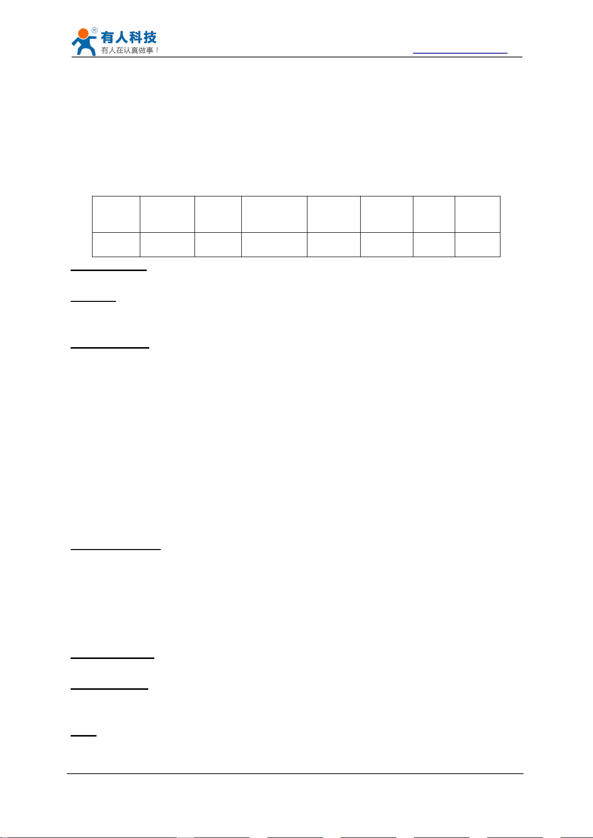
4.2.2 Serial command mode
Table 6 Protocol table of Serial command mode
frame
header
length
functio
n
byte
Backup
data area
Destinati
on port
Target
address
Data
Sum
check
2
2
(n+m+5)
122mn
1
Bit1:If it is a short connection, it sends data, and then will be disconnected; if it is long
Bit2:Indicates that the target address is IP or domain name. If it is IP, the target address is 4
Bit7:Under the cut protocol, reply frame contains only data; Under the full protocol, reply
First byte:If it is a short connection, this position is TCP waits for the timeout time (1-255), if
Second byte:Reserve
In this mode, the user can send the serial data to a different server address, this pattern can be
use udp or TCP client sends data to the server.
Customer MCU send packets according to the following format, parsing module is finished, only
the n bytes of data sent to the destination address.When data is returned, not analytical data from
serial port output directly.
frame header:
0x55 0xAA(Constant)
Length:
Starting from the function byte, to Sum check (does not contain the sum check) all bytes.
High byte at the front
Function byte:
Bit0:(UDP:0 ;TCP:1)
Bit1:(Short connection:0;Long connection:1)
Bit2:(IP:0;Domain name:1)
Bit7:(cut protocol:0;full protocol:1)Note: currently only supports cut protocol
Notes:
connection, it sends data, connection will remain, until the re changing the target address.
bytes; if the domain name, the target address length for the entire domain name string length
(the last byte address is ‘\0’, that is the end of the string).
frame has "failed to send", "waiting for", "UDP radio response equipment IP" frame data.
Backup data area:
the send command is completed, did not receive a response, then wait a few seconds and
the corresponding, if 5, said to wait for the 5S to disconnect; if the sending command,
immediately receive the returned data, then immediately disconnected; if it is long connection,
this position is 0x00.
Destination port:
Little endian, low byte in the former,such as port 23, here are 0x17 0x00
Target address:
If it is IP, is 4 bytes, for example, 192.168.0.7 said 0x07 0x00 0xA8 0xC0; if it is a domain
name, then the address of indefinite length,ending with the’\0'.
Data:
Variable length,the maximum not exceeding 1000bytes.
Jinan USR IOT Technology Limited Page 21 of 77 tec@usr.cn

USR-WIFI232-B2 User Manual http://www.usriot.com
4.2.3 GPIO mode
GPIO n IN, Set GPIOn as input, Response GPIO OK or GPIO NOK;
GPIO n OUT 0, Set GPIOn as output and output ‘0’, Response GPIO OK or GPIO NOK;
GPIO n OUT 1, Set GPIOn as output and output ‘1’, Response GPIO OK or GPIO NOK;
GPIO n SW, Set GPIOn as output and switch the output status, Response GPIO OK or
GPIO n PWM m1 m2, Set GPIOn output a wave: m1 is ‘high’ duration and m2 is ’low’
GPIO n GET, Read GPIOn status, Response I0,I1,O0,O1, means ” input low ” , ” input
4.2.4 HTTPD Client mode
Sum check:
From the function word to check byte (does not contain a check byte), add Sum check.
The following is an example of a specific application:
send data:0x55 0xaa 0x00 0x0a 0x00 0x00 0x00 0x21 0x00 0x85 0x00 0xA8 0xC0 0x01 0x0f
Length:0x00 0x0a
Function byte:0x00 (UDP;Short connection;IP;cut protocol)
Destination port:0x21 0x00(33)
Target address:0x85 0x00 0xA8 0xC0 (192.168.0.133)
Data:0x01(data length :1)
Sum check:0x0f (0x00+0x00+0x00+0x21+0x00+0x85+0x00+0xA8+0xC0+0x01=0x0f)
USR-WIFI232-B2 module support GPIO mode:At GPIO,UART (TXD/ RXD/CTS/RTS) defined as
GPIO and others (Ready/Link/) also defined as GPIO pin.
When module works at GPIO mode, PC and other equipments can setup connection (TCP/UDP)
through WiFi, then read/write GPIO information through command.
GPIO NOK;
duration (Time unit is ‘ms’ and minimal is 10ms), Response GPIO OK or GPIO NOK;
high”,”output low”,”output high”
Notes: n can be 3, 4, 5, 6, 8, 9 corresponding module pin. GPIO 4 can only defined as input and
GPIO 3 can only defined as output.
GPIO READ returns all current IO status, and GPIO n GET said method. Such as, I1I1I0I0I0I0O1,
I said input, O output. 0 low, 1 express high.4 pin is negated. Read the 1 actual 0 actual 1, read
the 0.
This mode is used to send data to the HTTP server.
After setting the HTTP header format by webpage or AT command, the data sent each time by
UART will add the HTTP header automatically.Convenient for the user directly submit data or
read data from the HTTP server.
Below is the specific application, for example:
The first set HTTP parameters using AT instructions.
AT+HTTPURL=192.168.1.1,80 The serveraddress and portsettings
AT+HTTPTP=POST Set the HTTP type, GET, PUT or POST
AT+HTTPPH=/set Set the path,the mostis50 bytes
AT+HTTPCN=keep-alive Set the Connection,maximum length of 20bytes
AT+HTTPUA=lwip13.2 Set the User-Agent,maximum length of 20bytes
Jinan USR IOT Technology Limited Page 22 of 77 tec@usr.cn
USR-WIFI232-B2 User Manual http://www.usriot.com
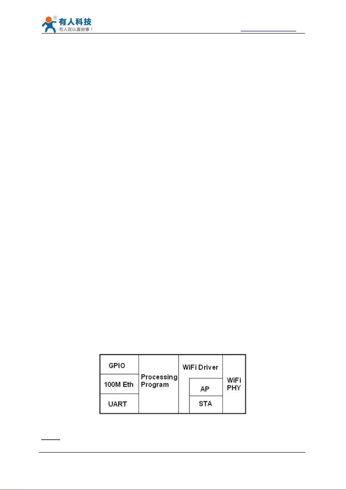
4.3 Wireless Networking
Figure 15 USR-WIFI232-B2 Functional Architecture
If the sending data is 1234.In the 80 port of 192.168.1.1 will receive the following data
POST /set HTTP /1.1
Connection:keep-alive
User-Agent:lwip1.3.2
Content-Length:4
Host:192.168.1.1:80
1234
If the HTTP type is GET, the 80 port 192.168.1.1 receive data
POST /set1234 HTTP /1.1
Connection:keep-alive
User-Agent:lwip1.3.2
Content-Length:0
Host:192.168.1.1:80
Data received from server will be directly sent to the serial port,without any treatment.
Note: after V5.01.14 version of the firmware it add a new method of HTTP header definition,
called the new mode, the way at above, is called the old mode.
Users can custom HTTP headers in the way of the new mode, can add, delete, modify the
contents of each HTTP header (if the HTTP request type is POST/PUT, module will automatically
add the Content - Length).Including the AT + HTPMODE, AT + HTPSV, AT + HTPTP, AT +
HTPURL, AT + HTPHEAD, specific instructions please refer to the AT command set process
section.Similarly, also has the corresponding Settings page in the web page.
Note: in the new mode, if you use the AT command set HTTP headers, Please use the
"<<CRLF>>" instead of carriage "return",in the web page,you don't need to worry about the
"return".
USR-WIFI232-B2 module can be configured as both wireless STA and AP base on network type.
Logically there are two interfaces in USR-WIFI232-B2. One is for STA, and another is for AP.
When USR-WIFI232-B2 works as AP, other STA equipments are able to connect to wireless LAN
via USR-WIFI232-B2 module. Wireless Networking with USR-WIFI232-B2 is very flexible.
Following figure shows the functional architecture of USR-WIFI232-B2 module:
Notes:
Jinan USR IOT Technology Limited Page 23 of 77 tec@usr.cn

USR-WIFI232-B2 User Manual http://www.usriot.com
4.3.1 STA
Figure 16 USR-WIFI232-B2 Basic Wireless Network Structure
4.3.2 AP
AP: that is the wireless Access Point, the founder of a wireless network and the center of the
network nodes. The wireless router we use at home or in office may be an AP.
STA: short for Station, each terminal connects to a wireless network (such as laptops, PDA and
other networking devices) can be called with a STA device.
Infrastructure: it’s also called basic network. It built by AP and many STAs which join in.
The characters of network of this type are that AP is the center, and all communication between
STAs is transmitted through the AP. The figure following shows such type of networking.
Because USR-WIFI232-B2 can be set to AP, can also be set to STA, so the USR-WIFI232-B2 can
be achieved easily wireless ad hoc network.
As showing in the figure below, USR-WIFI232-B2 (1) can be treat as an AP, and USR-WIFI232B2 (2), USR-WIFI232-B2 (3) and the laptop are STAs connected to USR-WIFI232-B2 (1).
Meanwhile, all USR-WIFI232-B2 modules can connected to user device via UART interface. All
USR-WIFI232-B2 modules can be operated and managed through the laptop. So it is convenient
to O&M all USR-WIFI232-B2 modules. Moreover, in such Adhoc network structure, the whole
coverage of a wireless network can be extended easily.
Jinan USR IOT Technology Limited Page 24 of 77 tec@usr.cn
 Loading...