

Shandong USR IOT Technology USR C215A User Manual

h.usriot.com
USR-C215a
User Manual
File Version: V1.0
Jinan USR IOT Technology Limited / 40 www.usriot.com
1

h.usriot.com
Contents
1. Quick Start.........................................................................................................................................................................4
1.1. Hardware Testing Environment.......................................................................................................................... 4
1.2. Data Transmission Testing.................................................................................................................................. 5
2. Overview............................................................................................................................................................................ 6
2.1. Brief Introduction................................................................................................................................................... 6
2.2. Features..................................................................................................................................................................6
2.3. Parameters.............................................................................................................................................................6
3. Hardware............................................................................................................................................................................7
3.1. Hardware Information...........................................................................................................................................7
3.1.1. Dimensions................................................................................................................................................. 7
3.1.2. Pin Defination............................................................................................................................................. 7
3.1.3. Antenna....................................................................................................................................................... 8
3.1.4. Evaluation kit.............................................................................................................................................. 8
3.2. Hardware Reference Design...............................................................................................................................9
3.2.1. Typical Application Connection............................................................................................................... 9
3.2.2. Power Interface.......................................................................................................................................... 9
3.2.3. UART Interface........................................................................................................................................ 10
3.2.4. Reset & Reload........................................................................................................................................10
4. Module Function............................................................................................................................................................. 11
4.1. Wireless Network Mode..................................................................................................................................... 11
4.1.1. Work as STA.............................................................................................................................................11
4.1.2. Work as AP............................................................................................................................................... 12
4.1.3. Work as AP+STA..................................................................................................................................... 12
4.1.4. Encryption Type....................................................................................................................................... 12
4.2. Work Mode...........................................................................................................................................................13
4.2.1. Transparent Transmission Mode.......................................................................................................... 13
4.2.1.1. Short Description......................................................................................................................... 13
4.2.1.2. UART Frame.................................................................................................................................13
4.2.2. Command Mode...................................................................................................................................... 14
4.3. Socket Connection............................................................................................................................................. 14
4.4. Search in LAN..................................................................................................................................................... 15
4.5. Registration Packet Mechanism.......................................................................................................................15
4.6. Usrlink (Fast Networking Protocol).................................................................................................................. 15
4.7. Simplelink.............................................................................................................................................................17
4.8. Class RFC2217...................................................................................................................................................18
5. Setting Method................................................................................................................................................................19
5.1. Webpage.............................................................................................................................................................. 19
5.1.1. WiFi Parameter Setting.......................................................................................................................... 20
5.1.2. Transparent Transmission Parameter Setting.................................................................................... 21
5.1.3. Extra Function..........................................................................................................................................22
5.1.4. System Setting.........................................................................................................................................23
5.1.5. About USR................................................................................................................................................ 24
Jinan USR IOT Technology Limited / 40 www.usriot.com
2

h.usriot.com
5.2. AT Command Instructions................................................................................................................................. 24
5.2.1. AT Command Description...................................................................................................................... 25
5.3. AT Instruction Set................................................................................................................................................26
5.3.1. AT Command List.................................................................................................................................... 26
5.3.1.1. AT+E...............................................................................................................................................27
5.3.1.2. AT+WMODE..................................................................................................................................27
5.3.1.3. AT+ENTM...................................................................................................................................... 28
5.3.1.4. AT+MID.......................................................................................................................................... 28
5.3.1.5. AT+RELD.......................................................................................................................................28
5.3.1.6. AT+Z...............................................................................................................................................28
5.3.1.7. AT+H (not available now)............................................................................................................29
5.3.1.8. AT+CFGTF.................................................................................................................................... 29
5.3.1.9. AT+UART.......................................................................................................................................29
5.3.1.10. AT+UARTTE............................................................................................................................... 30
5.3.1.11. AT+NETP..................................................................................................................................... 30
5.3.1.12. AT+TCPLK.................................................................................................................................. 31
5.3.1.13. AT+TCPDIS................................................................................................................................ 31
5.3.1.14. AT+SOCKB................................................................................................................................. 31
5.3.1.15. AT+TCPDISB..............................................................................................................................32
5.3.1.16. AT+TCPLKB................................................................................................................................32
5.3.1.17. AT+WSSSID............................................................................................................................... 32
5.3.1.18. AT+WSKEY.................................................................................................................................33
5.3.1.19. AT+WANN...................................................................................................................................33
5.3.1.20. AT+WSMAC................................................................................................................................34
5.3.1.21. AT+WSLK....................................................................................................................................34
5.3.1.22. AT+WSLQ................................................................................................................................... 34
5.3.1.23. AT+WSCAN................................................................................................................................ 35
5.3.1.24. AT+WSDNS................................................................................................................................ 35
5.3.1.25. AT+LANN.................................................................................................................................... 35
5.3.1.26. AT+WAP...................................................................................................................................... 36
5.3.1.27. AT+WAKEY.................................................................................................................................36
5.3.1.28. AT+WALK....................................................................................................................................36
5.3.1.29. AT+PLANG..................................................................................................................................37
5.3.1.30. AT+DTDDIS................................................................................................................................ 37
5.3.1.31. AT+DTDID...................................................................................................................................37
5.3.1.32. AT+WRMID................................................................................................................................. 38
5.3.1.33. AT+ASWD................................................................................................................................... 38
5.3.1.34. AT+SMTLK..................................................................................................................................38
5.3.1.35. AT+USERVER............................................................................................................................38
5.3.1.36. AT+RPTMAC.............................................................................................................................. 39
5.3.1.37. AT+WRRPTMAC....................................................................................................................... 39
6. Contact Us.......................................................................................................................................................................40
7. Disclaimer........................................................................................................................................................................40
8. Update History................................................................................................................................................................ 40
Jinan USR IOT Technology Limited / 40 www.usriot.com
3
h.usriot.com
1. Quick Start
1.1. Hardware Testing Environment
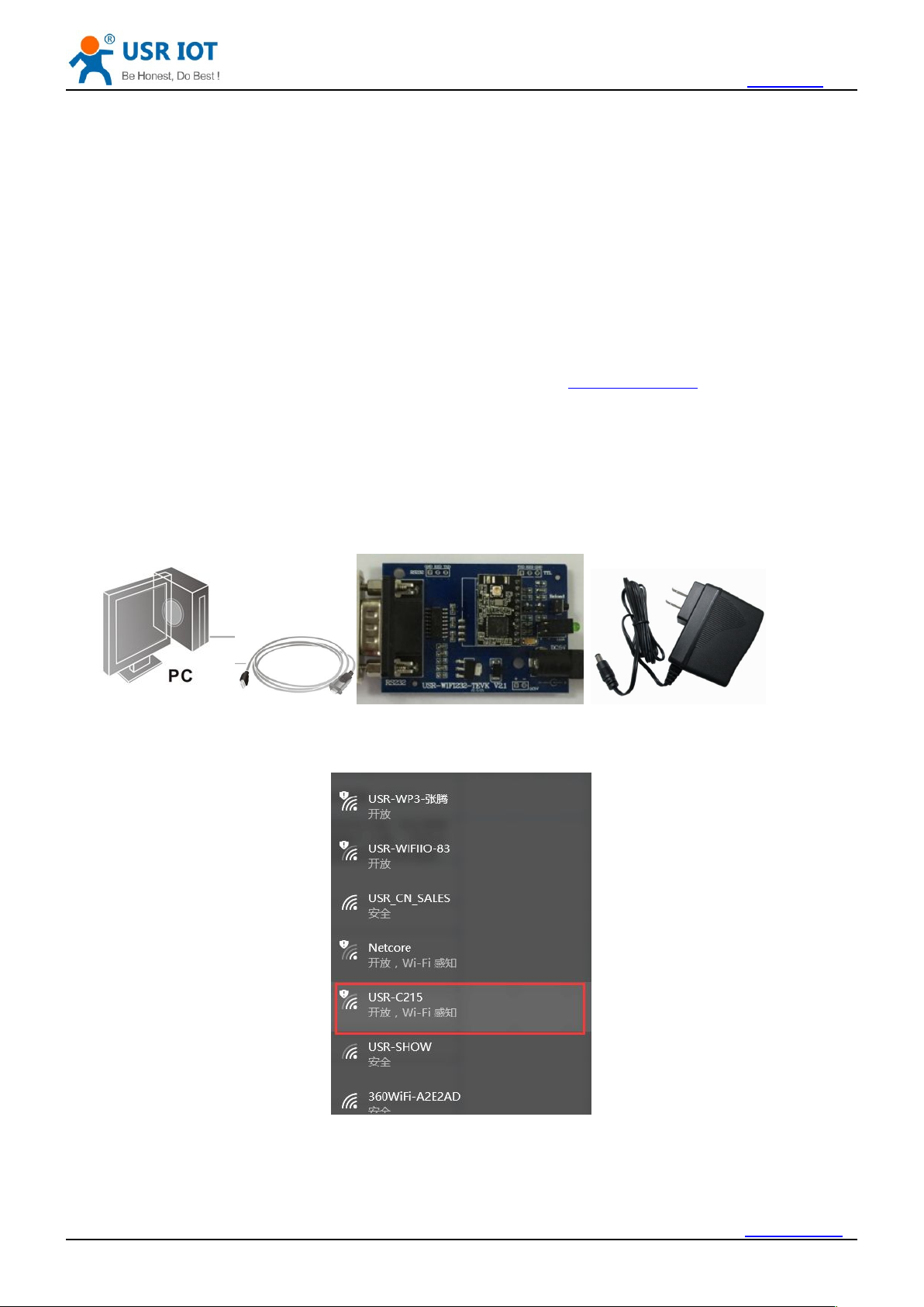
1. Hardware connection: Connect the module with PC by serial cable, power on, the Ready indicator will
2. Wi-Fi connection: Open Wi-Fi on your PC, scan and join the module network: USR-C215.
USR-C215 is a cost effective serial to WiFi module, which allows almost any serial devices to be
connected to a new or existing WiFi network, realize the two-way data transparent transmission between
UART and WiFi network interface.
This chapter aims at getting start USR-C215 quickly. It’s recommended that user read this chapter
systemically and operate it according to instructions to make a scientific knowledge. Following chapter will
introduce specific details, user can read interested chapter according to need.
If you have any question, feed it back to customer center please: http://h.usriot.com
For quick testing, our evaluation kit is recommended. Testing steps as follows:
be on.
Jinan USR IOT Technology Limited / 40 www.usriot.com
4
h.usriot.com
1.2. Data Transmission Testing
SSID: USR-C215
Encryption type: open, none
UART settings: 115200, 8, 1, N
Net settings: TCP, Server, 8899, 10.10.100.254
IP address of module: 10.10.100.254
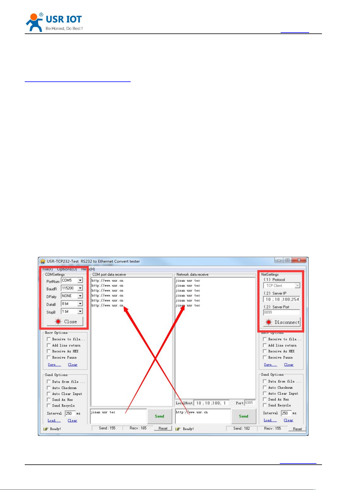
We supply testing software “USR-TCP232-Test.exe”, pls download from this link:
http://www.usriot.com/usr-tcp-test-v1-3/
Module default parameters:
Steps for UART to Wi-Fi data transmission:
1. Open “USR-TCP232-Test.exe”, on the left is COM part, on the right is Net part.
2. UART settings: UART settings should be the same with module, that is : 115200, N, 8, 1
3. Click Open to open the serial port.
4. Socket connection: Module default setting is TCP Server, so we should select TCP Client as protocol.
Server IP and Port is module IP and Port: 10.10.100.254; 8899.
5. Click Connect to establish TCP connection
6. Now we can realize data transmission between UART and WiFi.
The flow direction from UART to Net: COM of PC--> COM of module--> WiFi of module--> Net of PC.
The flow direction from Net to UART: Net of PC--> WiFi of module--> COM of module--> COM of PC.
Jinan USR IOT Technology Limited / 40 www.usriot.com
5
h.usriot.com
2. Overview
2.1. Brief Introduction
Can work as AP mode, in this mode, other WiFi terminals can join it for communication. Also can work
Support UART transparent transmission, switch by AT command
2.2. Features
Support Wi-Fi@2.4 GHz 802.11b/g/n wireless standard
Support WEP, WPA/WPA2 security
Support AP, STA, AT+STA work mode
Integrated serial to WiFi transmission function, multiple UART rate for selection
Support TCP/UDP Client registration mechanism
Simplelink/Usrlink fast network setting
Automatic baudrate adaptation which is similar to RFC2217
3.3V single power
Low power mode, support deep sleep
2.3. Parameters
The USR-C215 is integrated with MAC, baseband IC, RF transceiver unit and power amplifier. With
built-in low power operation mechanism, can effectively achive low power running. Support WiFi protocol and
TCP/IP protocol, with simple settings, realize connection for serial devices with network.
Dimensions of module: 22*13.5*6mm, single row 1*10 2m encapsulation
Basic functions of module:
as STA mode, join wireless router and realize transmission.
Parameters Value
Wirless standard 802.11 b/g/n
17.0 dBm @ 1 DSSS
Transmit
Wireless
Parameters
Hardware
Parameters
Jinan USR IOT Technology Limited / 40 www.usriot.com
Receive sensitivity
Antenna
Interface UART
Working voltage 3.0V~3.6V
Working current
15.0 dBm @ 11 CCK
13.5 dBm @ 54 OFDM
–91.5 dBm @ 1 DSSS
–87.5 dBm @ 11 DSSS
–80.5 dBm @ 54 OFDM
on board ceramic antenna
In AP mode: average 70mA@3.3V
In STA mode: average 30ma@3.3V
6
h.usriot.com
3. Hardware
3.1. Hardware Information
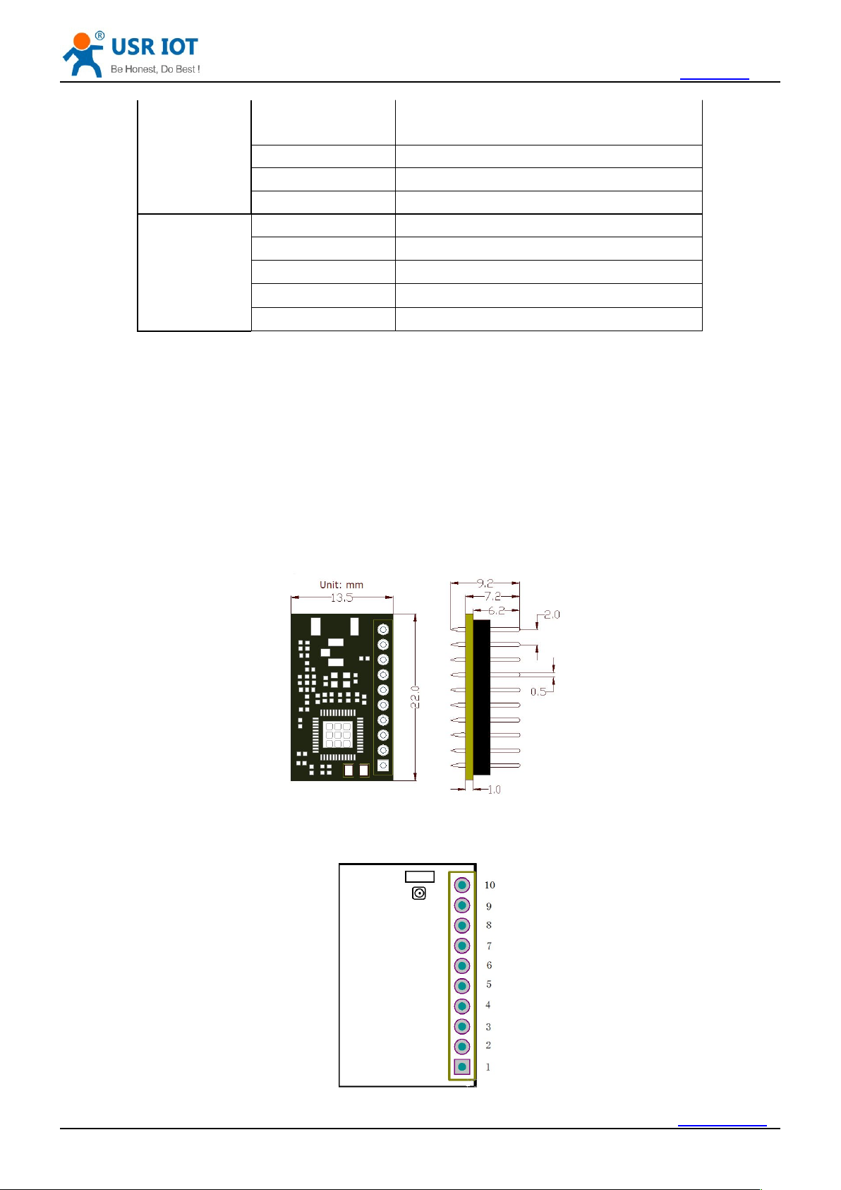
3.1.1. Dimensions
3.1.2. Pin Defination
Software
Parameters
Working
temprature
Storage temprature -55°C - 125°C
Dimensions 22mm x 13.5mm x 6mm
External interface Pins plug
Network type AP, STA, AP+STA
Security WEP/WPA-PSK/WPA2-PSK
Encryption TKIP,AES ,TKIP/AES
Net protocol IPv4, TCP/UDP
User config AT + command, Webpage
-30°C - 70°C
Dimension of module is 22.0*13.5mm, error±0.2mm
Jinan USR IOT Technology Limited / 40 www.usriot.com
7
Pin Defination List:
3.1.3. Antenna
3.1.4. Evaluation kit
Pin Name Type Description
1 GND P GND
2 VDD P Positive of power, 3.3V
3 RELOAD I Pull down 1-3s: start simplelink
Pull down more than 3s: reload to factory defaults
4 RESET I Reset, effective in low level
5 UART_RX I Receive
6 UART_TX O Transmit
7 PWR_SW N Vacant, not available
8 WPS N Vacant, not available
9 READY O Working indicator, effective in low level, can connect
external LED
10 nLINK O WiFi link indicator, effective in low level, can connect
external LED
h.usriot.com
<Note>
In Type list: power is expressed as P, input is expressed as I, output is expressed as O, not available is
expressed as N
Antenna Type: Ceramic Antenna
Antenna GAIN: 2.5dbi
We supply evaluation kit for users convenient development. As shown in below image, user can choose
UART interface for communication
Jinan USR IOT Technology Limited / 40 www.usriot.com
8
Evaluation kit interface description
3.2. Hardware Reference Design
3.2.1. Typical Application Connection
3.2.2. Power Interface
Function Name Description
External
interface
LED Ready Green light, module working indicator
Button nReload Reload to factory defaults
DC Jack 5V power input jacker
DB9 9-Pin male connector
nLink Red, nLink/GPIO indicator
h.usriot.com
Switching power supply is recommended. VCC working voltage range from 3.0V~3.6V, 3.3V is the best.
Power module by main power pin, the pin be in parallel with storage capacitance and high frequency
Jinan USR IOT Technology Limited / 40 www.usriot.com
9
capacitance. Circuit diagram as shown below:
3.2.3. UART Interface
3.2.4. Reset & Reload
Power Supply Characteristics
Symbol Parameter Min Type Max Unit
V_MAIN Power supply voltage 3.0 3.3 3.6 V
h.usriot.com
<Note> Io current
AP: 70mA@3.3V
STA: 30mA@3.3V
If communicate with MCU(3.3V) directly, should connect TXD of module to RXD of MCU, connect RXD of
module to TXD of MCU. If MCU is 5V level, a switching circuit is needed, see below diagram:
USR-C215 support hardware reload function, by connect nReload pin with external button or setting pin.
When pull down to “0” for 1~3s, simplelink function will start. When pull down to “0” for more than 3s, module
will restore to factory defaults. Here should link to a pull-up resistor (4.7K~10K)
nReset: reset signal, module will restart when it is pulled down. There exist a 100K resistance pull up to
3.3V. When module is powered on or break down, MCU will reset the module, pull down pin at least 0.5s, then
pull up or vacant.
Reference diagram as follows:
Jinan USR IOT Technology Limited / 40 www.usriot.com
10
h.usriot.com
4. Module Function
4.1. Wireless Network Mode
AP: Access Point, it is the center of wireless network. For example router, router is an AP, other
STA: Station, it is the terminal of wireless netwotk. For example laptop, PAD, cell phone.
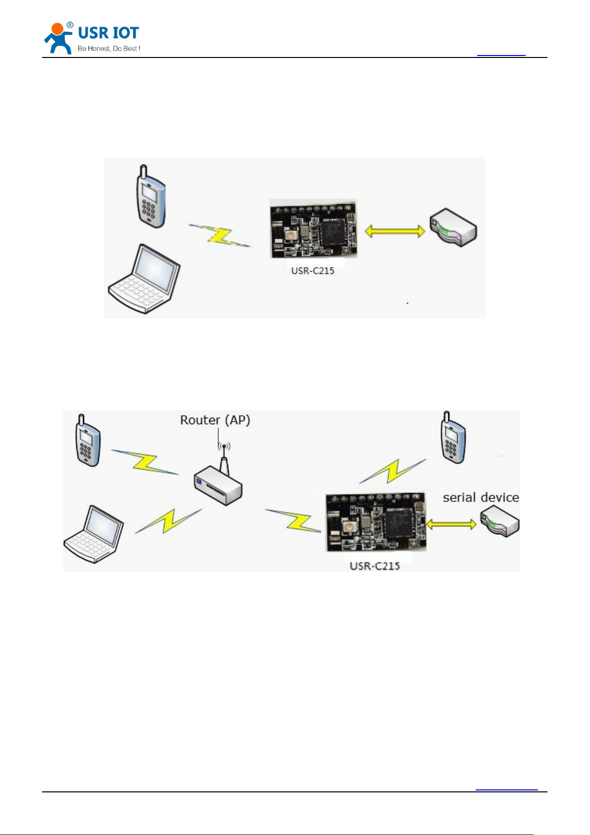
4.1.1. Work as STA
There are 3 types wireless network mode: AP, STA, AP+STA
<Description>
stations can connect to each other throught it.
It is the most commonly used network type for module to work as STA. Consist of a AP(router) and multi
STAs, see below image. The AP is in central position, communication between STAs forward by AP.
Jinan USR IOT Technology Limited / 40 www.usriot.com
11
h.usriot.com
4.1.2. Work as AP
4.1.3. Work as AP+STA
4.1.4. Encryption Type
WEP
WPA-PSK/TKIP
WPA-PSK/AES
WPA2-PSK/TKIP
WPA2-PSK/AES
Module can work as AP, in AP mode, cell phone/PAD/PC can get access to module for data transmission
without any settings. Besides, user can log in module built-in webpage for configuration.
<Note>
When module works in AP mode, 3 STAs can join it.
Module can work as AT and STA at the same time, shown as below:
<Note>
In this mode, 3 STAs can join the module network
To ensure the safety of data communication, module supports variety of encryption type. Including:
Jinan USR IOT Technology Limited / 40 www.usriot.com
12

h.usriot.com
Work Mode
4.2. Work Mode
Transparent transmission mode
Command mode:
4.2.1. Transparent Transmission Mode
4.2.1.1. Short Description
WiFi network
SSID
Encryption
Password
Default TCP/UDP connection
Protocol
Type (Client/Server)
Destination Port
Destination IP
UART Interface
Baud rate
Data bit
Stop bit
Check bit
Hardware flow control (rts/cts)
4.2.1.2. UART Frame
USR-C215 support 2 work mode: transparent transmission mode and command mode
In this mode, module will transmit data between UART&WiFi, to realize the communication between serial
device and network device.
In this mode, user can query/set the UART and network parameters by AT commands. Use command
AT+ENTM to quit command and switch to transparent transmission mode.
The advantage of this mode is to realize plug and play between UART interface and network
communication, that will reduce the complexity for users. With essential parameter settings in advance, after
power on, module will automatically connect to the pre-set wireless network and server.
This mode is fully compatiable with users software, which reduce the workload for development of
intergrade wireless software.
Parameters need to set in advance
When module receive data sent from UART, it wil keep checking the time interval of 2 adjacent bytes. If
time interval is greater than frame time you set (default 20ms, can set by command AT+UARTTE), module will
Jinan USR IOT Technology Limited / 40 www.usriot.com
13
 Loading...