

Shandong New Beiyang Information Technology Co., ltd. BT-T080 Plus Service Manual

SERVICE MANUAL
Embedded Printer
BT-T080 Plus
Shandong New Beiyang Information Technology Co., ltd.

BT-T080 Plus Service Manual
- 1 -
Revision History
Date Version Description Author
2017-6-20 V1.0 Initial version.
Li Lingang
Wang Xinping
Wang Junxian
Chen Yi

BT-T080 Plus Service Manual
- 2 -
Declaration
This manual is special for embedded printer BT-T080 plus and it is not allowed to be modified without
permission. Shandong New Beiyang Information Technology Co., Ltd. (hereinafter referred to as “SNBC”)
reserves the right to improve products as new technology, components, software, and firmware available. If
users need the further data about these products, please feel free to contact SNBC or our distributors.
No part of this document may be reproduced or transmitted in any form or by any means, electronic or
mechanical, for any purpose without the express written permission of SNBC.
Copyright
Copyright © 2017 by SNBC.
Printed in China.
Version 1.0.
Trademark
Our registered trademark:
SNBC has been approved by following certifications:
ISO9001 Quality Control System Certification
ISO14001 Environmental Management System Certification
OHSAS18001 Occupational Health and Safety Management System Certification
IECQ QC 080000 Hazardous Substance Process Management System Certification
Contact us:
Address: No.169 huoju road, high-tech zone, Weihai, China
Hot line: 400-618-1368 800-860-1368
Fax: +86-631-5656098
PC: 264209
Website: www.snbc.cn

BT-T080 Plus Service Manual
- 3 -
Notes
1) Follow the steps in this manual hereafter during maintenance.
2) Make sure that the printer and the computer are turned off before plugging the communication cable,
changing print head or doing maintenance to the printer.
3) Take anti- static measures, when replace print head or other electronic components.
4) Time between turning on and turning off the printer is no less than 20 seconds.
5) Do not allow the printer to print when there is no paper loading, otherwise the print head and platen
roller will be damaged.
6) Set the printing darkness in a lower grade as long as the print quality is acceptable. This will help to
keep the print head durable.

BT-T080 Plus Service Manual
- 4 -
Content
1 Printer characteristics .......................................................................................................................... - 1 -
1.1 Function .............................................................................................................................................- 1 -
1.2 Appearance and components .............................................................................................................-
1 -
1.3 Performance index .............................................................................................................................-
2 -
1.3.1 Print specification ...................................................................................................................... - 2 -
1.3.2 Cut mode .................................................................................................................................. - 2 -
1.3.3 Status detection ........................................................................................................................ - 2 -
1.3.4 Sensor position ......................................................................................................................... - 2 -
1.3.5 Paper specification ................................................................................................................... - 3 -
1.3.6 Lable paper specification .......................................................................................................... - 4 -
1.3.7 Print area .................................................................................................................................. - 5 -
1.3.8 Print and cut position ................................................................................................................ - 5 -
1.3.9 Power supply voltage ................................................................................................................ - 5 -
1.3.10 Reliability .................................................................................................................................. - 6 -
2 Whole printer and components ............................................................................................................ - 7 -
2.1 Printer overview ..................................................................................................................................-
7 -
2.2 Main control board module connecting diagram .................................................................................-
7 -
3 Disassembly and assembly .................................................................................................................. - 8 -
3.1 Disassemble the printer ......................................................................................................................- 8 -
3.1.1 Disassemble the print unit ......................................................................................................... - 8 -
3.1.2 Disassemble the print head .................................................................................................... - 13 -
3.1.3 Disassemble the paper feeding path module .......................................................................... - 14 -
3.2 Assemble the print unit ..................................................................................................................... -
15 -
4 Replacement and maintenance of key parts ..................................................................................... - 16 -
4.1 Print head maintenance and replacement ........................................................................................ - 16 -
4.1.1 Print head maintenance .......................................................................................................... - 16 -
4.1.2 Print head replacement ........................................................................................................... - 16 -

BT-T080 Plus Service Manual
- 5 -
4.1.3 Caution ................................................................................................................................... - 16 -
4.2 Platen roller maintenance and replacement ..................................................................................... -
16 -
4.2.1 Platen roller maintenance ....................................................................................................... - 16 -
4.2.2 Platen roller replacement ........................................................................................................ - 16 -
4.2.3 Caution ................................................................................................................................... - 17 -
4.3 Micro switch replacement ................................................................................................................. -
17 -
4.3.1 Micro switch replacement ....................................................................................................... - 17 -
4.3.2 Caution ................................................................................................................................... - 17 -
4.4 Sensor replacement ......................................................................................................................... -
17 -
4.4.1 Mark sensor replacement ....................................................................................................... - 17 -
4.4.2 Caution ................................................................................................................................... - 17 -
4.5 Cutter replacement ........................................................................................................................... -
17 -
4.5.1 Cutter replacement ................................................................................................................. - 17 -
4.5.2 Caution ................................................................................................................................... - 17 -
4.6 Print motor replacement ................................................................................................................... -
18 -
5 Printer Adjustment .............................................................................................................................. - 19 -
5.1 Paper near end sensor position adjustment ..................................................................................... - 19 -
5.2 Mark sensor position adjustment ...................................................................................................... -
20 -
6 Troubleshooting .................................................................................................................................. - 21 -
Appendix .................................................................................................................................................. - 23 -
Appendix 1 Product naming rule ............................................................................................................ -
23 -
Appendix 2 EEPROM setting table ......................................................................................................... -
23 -
Appendix 3 Command set ...................................................................................................................... -
24 -
Appendix 4 Easily damaged parts list ..................................................................................................... -
26 -
Appendix 5 Printer exploded view .......................................................................................................... -
28 -
Appendix 6 Parts list ............................................................................................................................... -
31 -
Appendix 7 Overall dimension ................................................................................................................ -
32 -
BT-T080 Plus Service Manual
- 1 -
1 Printer characteristics
1.1 Function
High speed printing
The print speed is 150mm/s;
High reliability
The lifetime of cutter is not less than 1 million times (60g recommended paper, the paper type is OJI
PD15/PD150R, room temperature 25°C);
The lifetime of printhead is not less than 100km (12.5% duty ratio, 60g recommended paper, paper
type is OJI FD210, room temperature 25°C);
MCBF 37,000,000 lines.
Single paper feeding path
This product is configured with one straight paper feeding path.
Adapt to single-type width paper
This product can adapt to paper with a width of 79.5±0.5 mm;
Semi-automatic paper feeding
This product has semi-automatic paper feeding function
Easy to maintain
The product adopts unique patented technology—platen roller slips away from the print head and it is
easy to clean the print head and clear the errors. If the cutter can’t reset, the user still can open the
platen and stationary blade at the same time without damaging the movable blade.
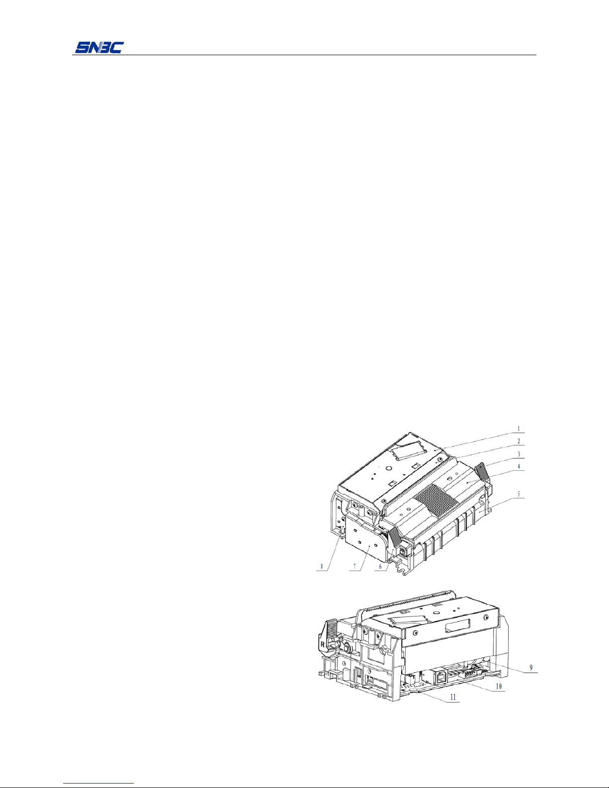
1.2 Appearance and components
The appearance is in the nature color of parts.
1—cutter
2—tear-off knife
3—right spanner
4—external path
5—mechanism holder
6—spanner
7—gear cover
8—grounding part
9—stepper motor
10—main control board
11—main control board protective film
Fig. 1.2-1 BT-T080 Plus embedded printer
BT-T080 Plus Service Manual
- 2 -
1.3 Performance index
1.3.1 Print specification
Model
Item
BT-T080 Plus
Print method Direct thermal line
Print direction Consistent with the paper feeding direction
Dot density 203dpi x 203dpi
Print width
Max.80mm
Max.640 dots
Print speed 150mm/s
Table 1.3.1 Print specification
Note: Dpi: printed dots per inch (1 inch ≈ 25.4 mm);
1.3.2 Cut mode
Full cut
Half cut
1.3.3 Status detection
No. Detection contents Sensor type
1 Mark/out of paper Photoelectric sensor
2 Print head position Micro switch
3 Print head temperature Thermistor
4 Paper near end Photoelectric sensor
5 Anti-pull Photoelectric sensor
6 Anti-jam Photoelectric sensor
Table 1.3.2
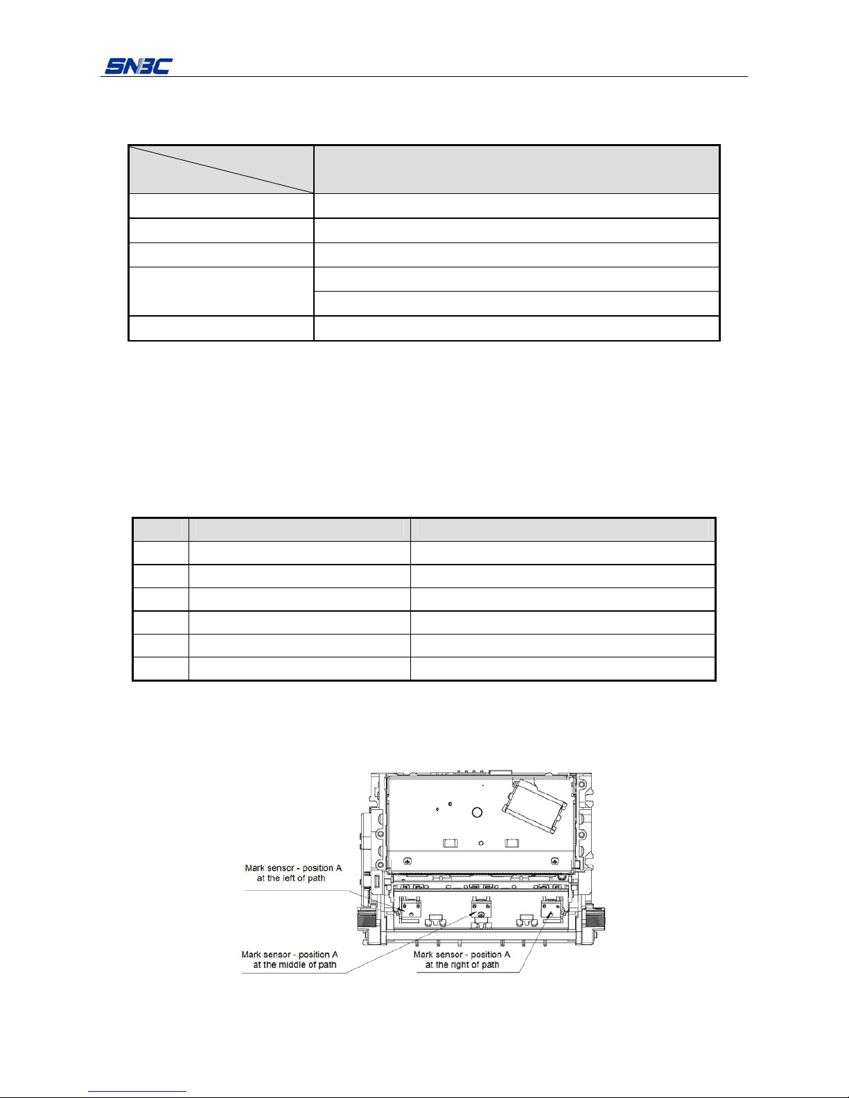
1.3.4 Sensor position
Fig.1.3.4.1 Sensor position 1
BT-T080 Plus Service Manual
- 3 -
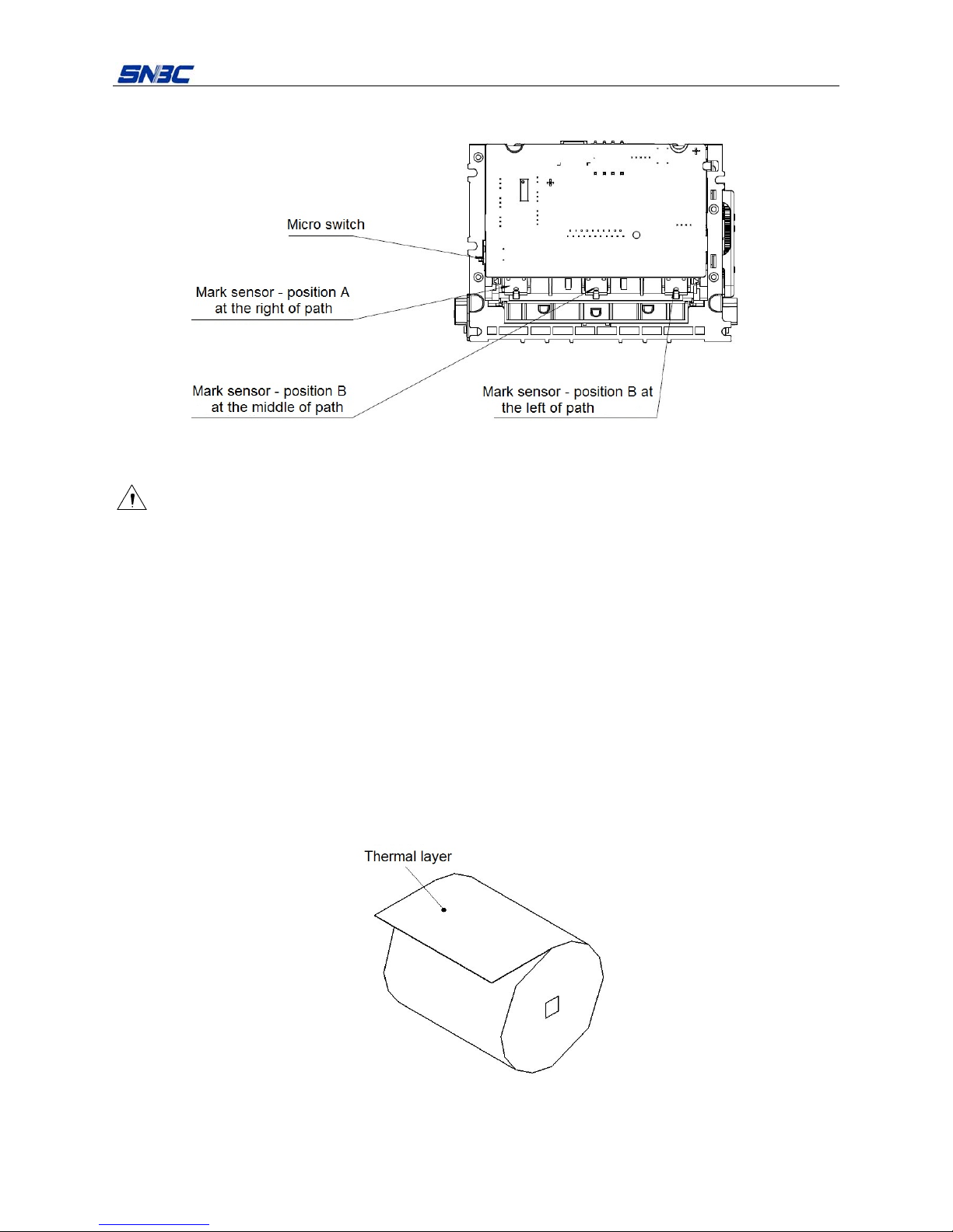
Fig. 1.3.4.2 Sensor position 2
Caution:
When the mark sensor is at position A, the marks are in the non-thermal layer;
When the mark sensor is at position B, the marks are in the thermal layer.
1.3.5 Paper specification
1) Paper type: thermal paper
2) Paper supply: continuous paper
3) The paper width is selected according to the selected configuration model:
Model: BT-T080 Plus 79.5±0.5mm
4) Paper roll specification:
Paper roll outer diameter (Max.): ф150 mm
Paper roll inner diameter (Min.): ф12.5mm, ф25.4mm
5) Thermal layer: outward
Fig. 1.3.5 Thermal layer diagram
6) Paper thickness: 60~100 μm
BT-T080 Plus Service Manual
- 4 -
7) Recommended paper:
Paper type Manufacturer
FD210 OJI Paper CO., LTD.
PD150 OJI Paper CO., LTD.
PD150R OJI Paper CO., LTD.
Table 1.3.5 Recommended paper
Caution:
Please use the recommended paper or its equivalents. Using the paper of low quality might affect the
print quality and shorten the lifetime of print head;
Do not stick paper onto the paper roll core shaft;
If the paper is contaminated by chemical or oil, it may discolor at the polluted spot or have poor printing
effect;
Do not rub the thermal side of paper with hard objects, otherwise the printing contents may be not
clear.
When the environment temperature goes up to 70℃, paper will discolor. Thus don’t use or store paper
under high temperature, high humidity and strong light conditions, etc.;
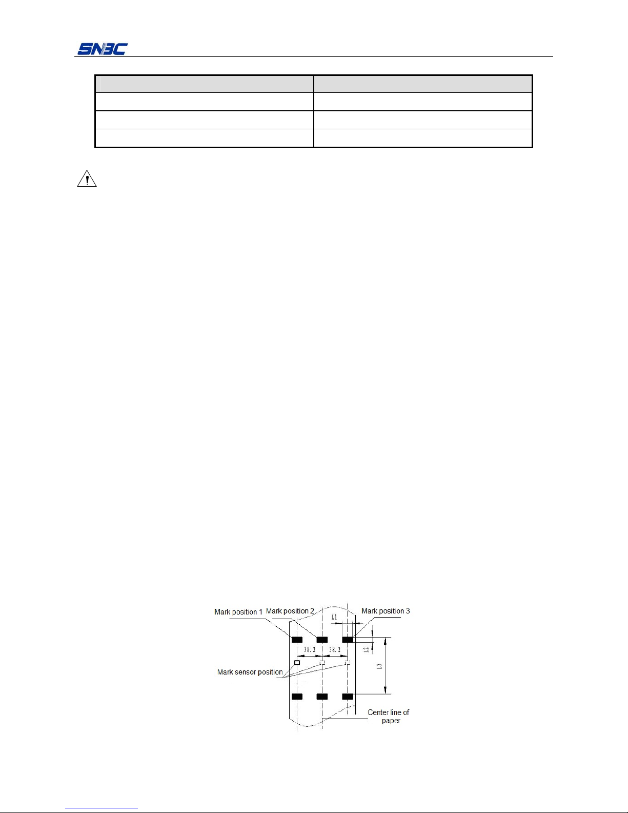
1.3.6 Lable paper specification
Except for the requirements of standard paper, the mark paper should aslo meet the following
requirements:
1) Mark position
The mark with the paper width is more than 79mm can be selected to be at the left, middle and right
positions of the thermal / non-thermal layer, as shown in Fig.1.2.6. Make sure that the marks on both sides
are completely covered by the mark sensor (distance from the mark sensors at both sides to the center line
of paper is 38.2mm).
2) When select the mark, the following parameters are recommended:
L1 makr height: 8mm≤L1≤Paper width
L2 makr height: 4mm≤L2≤8mm
3) The mark’s reflectivity should be less than 10%, and the reflectivity of the other parts along the paper
feeding direction within the width of the mark should be more than 75%.
Fig. 1.3.6 Mark position diagram
BT-T080 Plus Service Manual
- 5 -
Caution:
Due to the jitter during paper feeding and the difference in paper parameters, the positioning of mark
may have an error of ±1 mm;
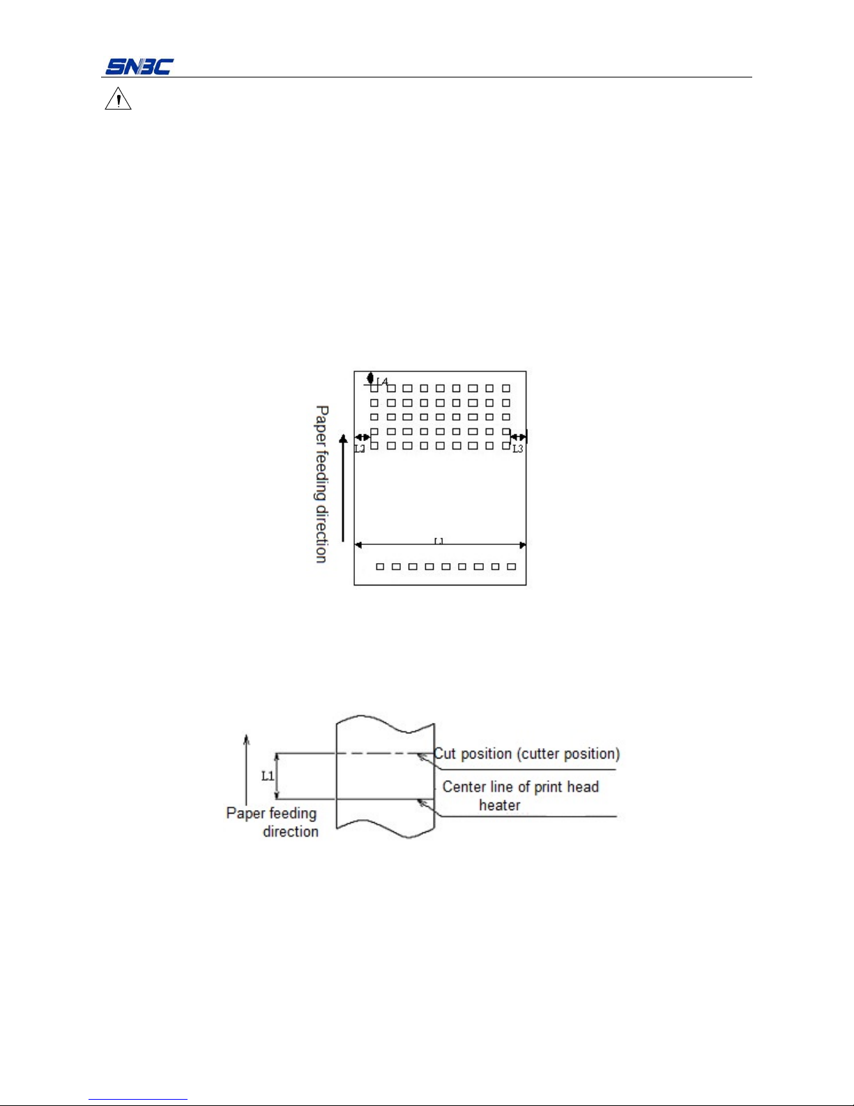
1.3.7 Print area
The path of the BT-T080 Plus embedded printing unit is suitable for paper with 80mm width, and the
specific paper width refers to the section 1.3.5 paper specification.
L1: Maximum printable width 80mm
L2: Left print margin adjustable
L3: Right print margin adjustable
L4: Top margin recommended: ≥5mm
Fig. 1.3.7 Print width diagram
1.3.8 Print and cut position
L1: 14.5mm
Fig. 1.3.8 Relationship between print and cut positions
1.3.9 Power supply voltage
1) Drive voltage: 24VDC±10%
Note: used to drive the print head and the motor.
2) Detection voltage: 3.3VDC±5%
Note: Used to detect the status of print head control, mark sensor, paper sensor, micro switch, etc.

BT-T080 Plus Service Manual
- 6 -
1.3.10 Reliability
Print device
MCBF: 37,000,000 lines (paper feeding)
Print head
Lifetime: 100km (12.5% duty ratio, 60g recommended paper, paper type is OJI FD210, room
temperature 25℃)
Cutter
Lifetime: 1 million times (60g recommended paper, paper type OJI PD15/PD150R, room temperature
25℃)
 Loading...