

Page 1
USER’S MANUAL
Label Printer
BTP-L540
Shandong New Beiyang Information
Technology Co., Ltd
Page 2

BTP-L540 User’s Manual
- 1 -
Declaration
Information in this document is subject to change without notice.
SHANDONG NEW BEIYANG INFORMATION TECHNOLOGY CO.,
LTD. (hereinafter referred to as “SNBC”) reserves the right to
improve products as new technology, components, software, and
hardware become available. If users need further data about these
products, please feel free to contact SNBC or our local dealer.
No part of this document may be reproduced or transmitted in any
form or by any means for any purpose without the express written
permission of SNBC.
Copyright
Copyright © 2012 by SNBC
Printed in China
Version 1.1
Trademark
Our Registered trademark:
Warning and caution
Warning:
Items shall be strictly followed to avoid injury or
damage to body and equipment.
Caution: Items with important information and prompts for
operating the printer.
Page 3

BTP-L540 User’s Manual
- 2 -
SNBC has been approved by the following
certifications:
ISO9001 Quality Control System
ISO14001 Environmental Management System
OHSAS18001 Occupational Health and Safety Management
System
IECQ QC080000 Hazardous Substance Process Management
System
Page 4

BTP-L540 User’s Manual
- 3 -
Safety Instructions
Before installing and using the printer, please read the following
items carefully.
1. Safety warning
The print head is a thermal element and it is at a high
temperature during printing or just after operation, therefore do
not touch it or its peripherals for safety’s sake
.
The print head is an ESD-sensitive device. To prevent damage,
do not touch either its printing parts or connecting parts.
2. Notices
1) Install the printer on a flat and stable surface;
2) Reserve adequate space around the printer so that convenient
operation and maintenance can be performed;
3) Keep the printer far away from water source, and do not expose
the printer to direct sunlight, strong light and heat;
4) Do not use or store the printer in a place exposed to high
temperature, high humidity or serious pollution;
5) Do not place the printer in a place exposed to vibration or
impact;
6) No condensation is allowed to the printer. In case of such
condensation, do not turn on the power until it has completely
gone away;
7) Connect the printer power to an appropriate grounding outlet.
Avoid sharing one electrical outlet with large power motors or
other devices that may cause the fluctuation of voltage;
Page 5

BTP-L540 User’s Manual
- 4 -
8) Disconnect the power when the printer is deemed to idle for a
long time;
9) Don’t spill water or other electric materials into the printer (e.g.
metal). In case this happens, turn off the power immediately;
10) Do not allow the printer to start printing when there is no
recording paper installed; otherwise the print head and platen
roller will be damaged;
11) To ensure quality print and normal lifetime, use recommended
paper or its equivalent;
12) Shut down the printer when connecting or disconnecting
interfaces to avoid damages to control board;
13) Set the print darkness to a lower grade as long as the print
quality is acceptable. This will help to keep the print head
durable;
14) Avoid turning on and off the printer frequently. It is advised to
turn on the printer at least 2 seconds after the printer is turned
off;
15) Do not disassemble the printer without permission of a
technician, even for repairing purpose;
16) Keep this manual safe and at hand for reference purpose.
Page 6

BTP-L540 User’s Manual
- 5 -
Contents
1 Product description ..................................................................... - 1 -
1.1 Introduction .......................................................................... - 1 -
1.2 Unpacking and checking...................................................... - 1 -
1.3 Appearance and module ..................................................... - 2 -
1.4 Introduction of main modules .............................................. - 3 -
2 Printer installation ....................................................................... - 5 -
2.1 Installation position .............................................................. - 5 -
2.2 Paper roll installation ........................................................... - 5 -
2.3 Power adapter connection ................................................... - 6 -
2.4 Communication cable connection........................................ - 7 -
2.5 Start the printer .................................................................... - 7 -
2.5.1 Power-on and self-test .................................................. - 7 -
2.5.2 Printing self-test page ................................................... - 8 -
2.6 Driver setup .......................................................................... - 8 -
3 Printer operations ..................................................................... - 11 -
3.1 LED, buzzer, feed button and LCD ................................... - 11 -
3.1.1 LED functions .............................................................. - 11 -
3.1.2 Button functions .......................................................... - 11 -
3.1.3 Buzzer functions .......................................................... - 12 -
Page 7

BTP-L540 User’s Manual
- 6 -
3.1.4 LCD functions .............................................................. - 12 -
3.2 Printer status and operation .............................................. - 12 -
3.2.1 Printer status ............................................................... - 12 -
3.2.2 Daily operations .......................................................... - 13 -
3.3 Printer parameter settings ................................................. - 14 -
3.3.1 Button menu settings .................................................. - 14 -
3.3.2 Detailed parameter setting range ................................ - 17 -
3.4 Sensor position adjustment ............................................... - 18 -
3.5 Print position adjustment ................................................... - 20 -
4 Routine maintenance ............................................................... - 23 -
4.1 Cleaning print head ............................................................ - 23 -
4.2 Cleaning the sensor ........................................................... - 23 -
4.3 Cleaning platen roller ......................................................... - 24 -
5 Troubleshooting ........................................................................ - 26 -
5.1 Troubleshooting ................................................................. - 26 -
5.2 Print quality problems ........................................................ - 28 -
6 Appendix ................................................................................... - 29 -
Appendix 1 technical specification ........................................... - 29 -
Appendix 1.1 main technical specifications ......................... - 29 -
Appendix 1.2 technical specifications of paper .................... - 32 -
Page 8

BTP-L540 User’s Manual
- 7 -
Appendix 2 self-test page ........................................................ - 33 -
Appendix 2.1 printer configuration information .................... - 33 -
Appendix 3 print and paper out position .................................. - 34 -
Appendix 4 communication interface....................................... - 36 -
Appendix 4.1 serial interface ................................................ - 36 -
Appendix 4.2 parallel interface ............................................. - 37 -
Appendix 4.3 USB interface ................................................. - 37 -
Appendix 4.4 Ethernet interface ........................................... - 38 -
Appendix 5 operation guide for paper loading under peel-off mode
(optional) .................................................................................. - 39 -
Page 9

BTP-L540 User’s Manual
- 1 -
1 Product description
1.1 Introduction
BTP-L540 label printer is an ideal label and barcode printing device
for office use, with delicate appearance and excellent performance.
It can apply to many fields, such as real-time label printing, product
label batch printing, transportation and logistics label printing,
medical label printing and business label printing.
BTP-L540 label printer can be connected to the peripherals via USB
or other interfaces and can provide universal drivers under the
operating systems such as Windows 2000/Windows XP/Windows
server 2003/ Windows Vista/ Windows server 2008/ Windows 7/
Windows 8 and other applications.
Main features:
Ø Thermal printing;
Ø Low noise, high speed printing;
Ø Easy paper loading, convenient operation;
Ø With 32 bit high speed microprocessor;
Ø Adopting heat history and auto temperature adaptation control;
Ø Adopting a new type of print head with long lifetime, high printing
quality;
Ø Supporting continuous paper, label paper, marked paper, etc.
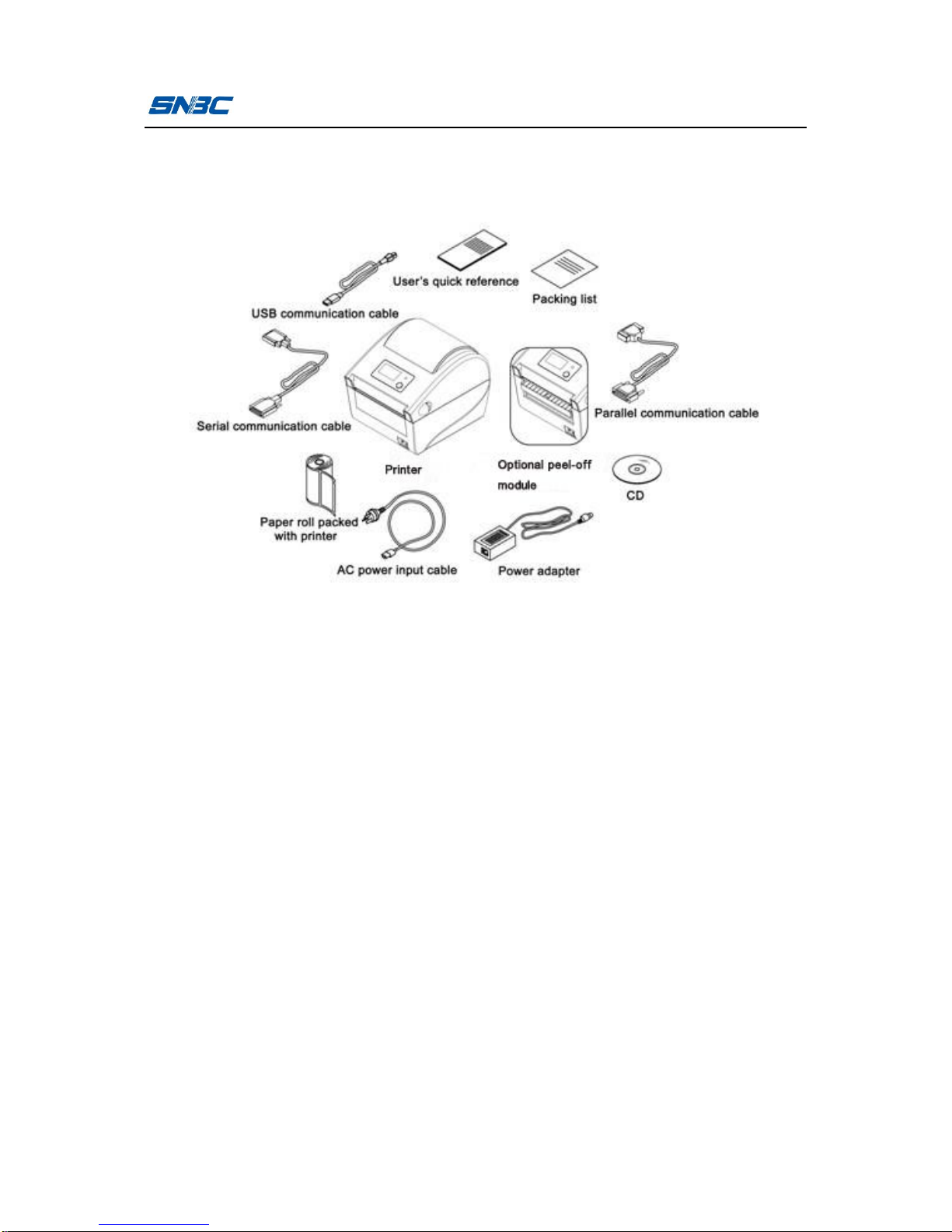
1.2 Unpacking and checking
Open the packaging, and check the items according to the packing
list. Please contact SNBC or your local dealer if there is shortage or
Page 10
BTP-L540 User’s Manual
- 2 -
damage (communication cables are optional depending on the
printer interface type).
Figure 1.2-1
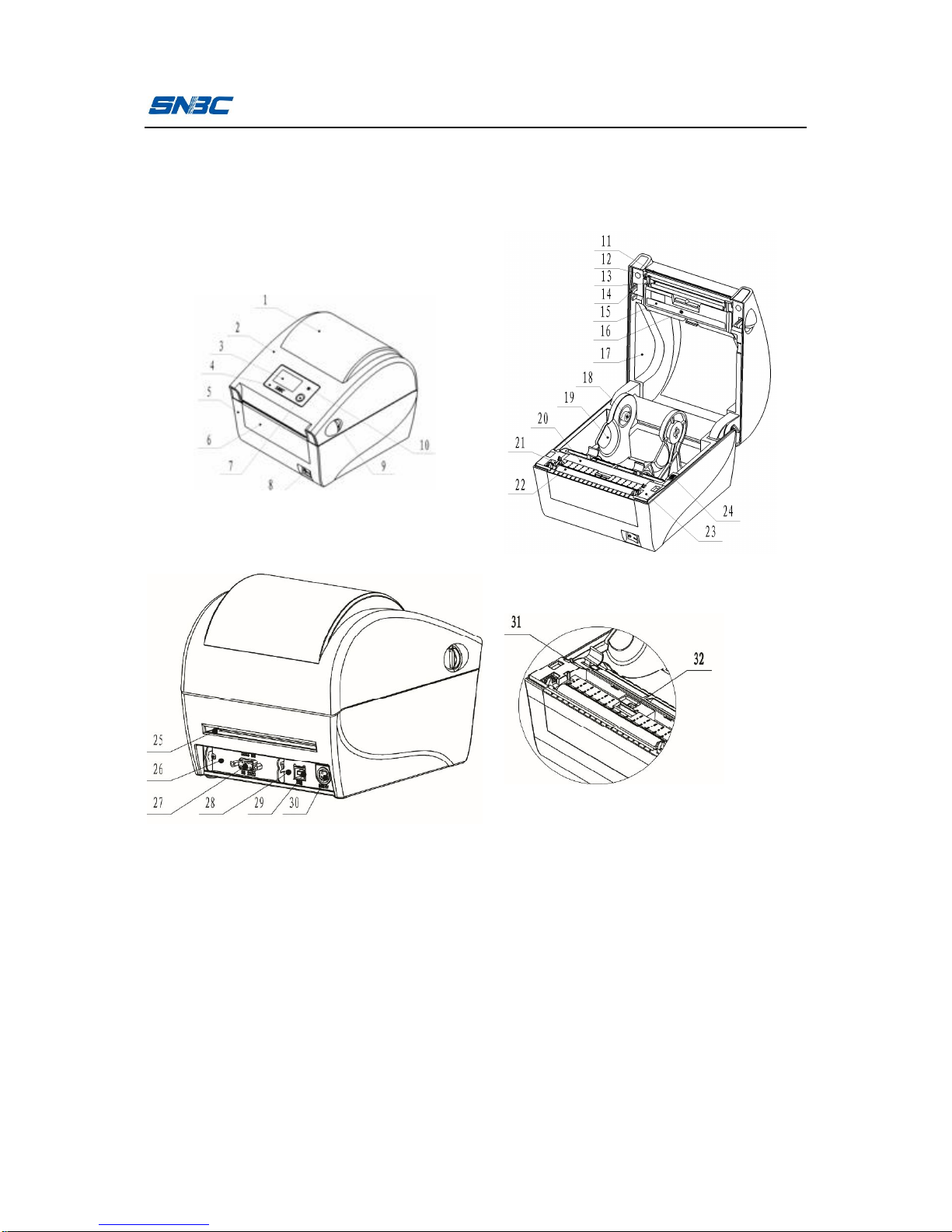
1.3 Appearance and module
1—window 2—top cover
3—LCD (optional) 4—Logo plate
5—bottom cover 6—guard board for bottom cover
7—button 8—power switch
9—cover open lever 10—LED
11—tear-off bar 12—print head fixing plate
13—print head 14—latch
15—guard board for print head 16—transmissive sensor
17—upper path 18—paper roll holder baffle
19—paper roll holder 20—sensor cover board
21—platen roller shaft sleeve 22—platen roller
23—lower path 24—paper roll holder thumb wheel
25—entrance for external paper roll 26—9-pin serial interface baffle
Page 11
BTP-L540 User’s Manual
- 3 -
27—serial interface 28—interface board
29—USB interface 30—24V power interface
31—micro switch 32—reflective sensor
1.4 Introduction of main modules
1) Button and LED (7, 10): indicate the printer status and complete
printing function;
2) Power switch (8): press “O” to power off and press “-” to power
on;
3) Transmissive sensor (16): used for calibration, detection and
location of media like label paper;
Page 12

BTP-L540 User’s Manual
- 4 -
4) Paper roll holder baffle (18), paper roll holder (19): support paper
roll holder and stop paper roll holder from shaking;
5) Print head micro switch (31): used to detect whether the print
head is uplifted or pressed down;
6) Reflective sensor (32): used for the calibration, detection and
location of media like black marked paper.
Page 13

BTP-L540 User’s Manual
- 5 -
2 Printer installation
2.1 Installation position
Flatly place the printer on the operation table, which must be
waterproof, moistureproof and dustproof. The maximal tilted angle
should not exceed ±15° during installation.
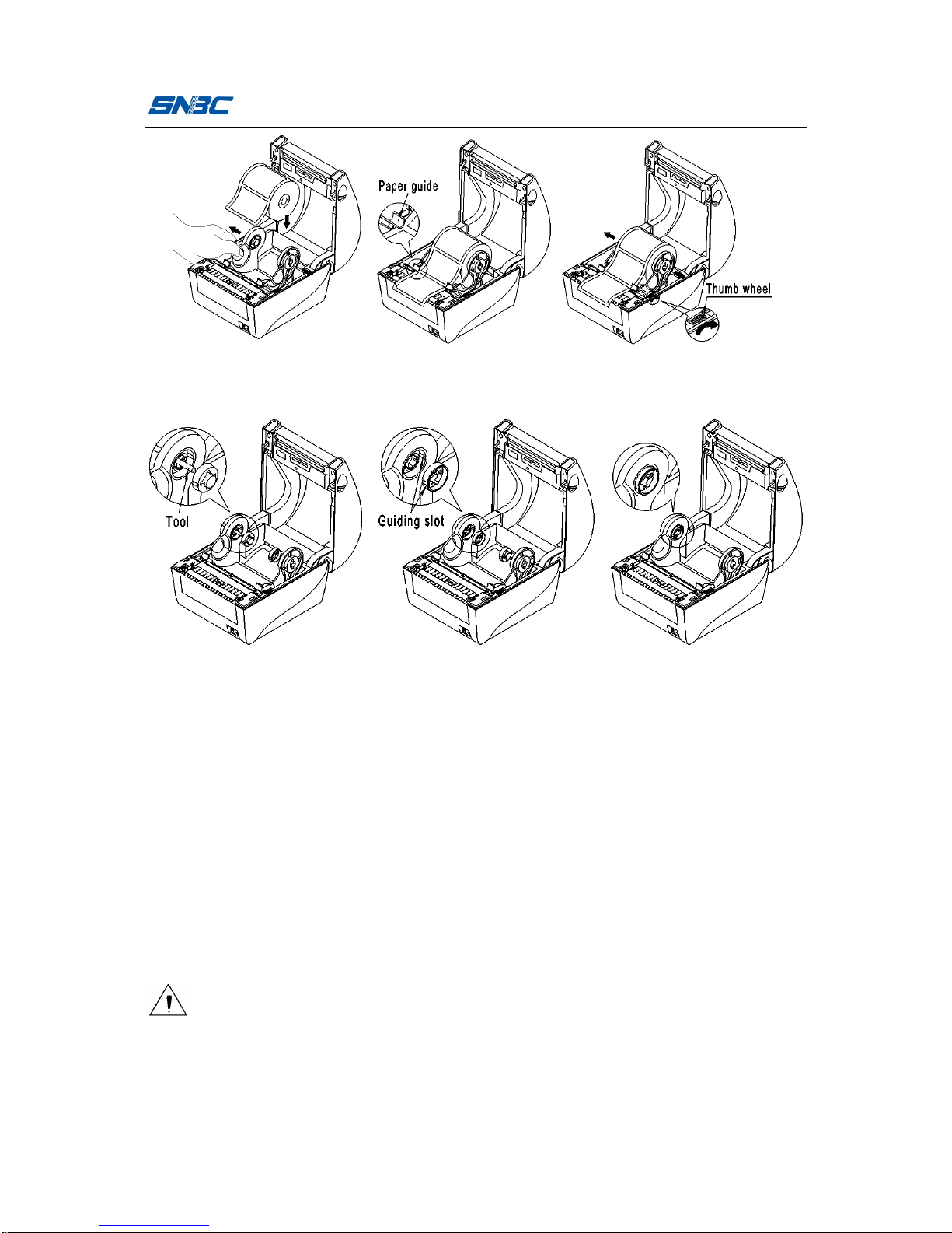
2.2 Paper roll installation
1) Pull the cover open lever towards the front of the printer and turn
the top cover upward to open it (see figure 2.2-1);
2) Pull the left and right paper holders apart and load the paper roll,
then pull the front of paper roll out to spread it in the print path,
and push the paper under the paper guide (see figure 2.2-2);
turn the thumb wheel properly in the direction shown in the figure
to decrease the force on paper roll (see figure 2.2-3);
3) Ensure the paper is installed in the path correctly, and close the
top cover;
4) If the diameter of paper roll is very big, use the corresponding
tool to remove the paper holder baffles, then turn the baffles, and
insert them into the center holes of the left and right paper
holders along the guiding slot (see figure 2.2-4);
Figure 2.2-1 open top cover
Page 14
BTP-L540 User’s Manual
- 6 -
Figure 2.2-2 load paper roll Figure 2.2-3 adjust thumb wheel
Figure 2.2-4 change the installation way of paper holder baffle
2.3 Power adapter connection
1) Ensure the printer is turned off;
2) Connect one end of the AC power input cable to power adapter,
and then insert the other end of the power adapter into the power
adapter interface on the back of printer;
3) Insert the other end of AC power input cable into the 220V power
socket.
Caution
n If leaving the printer idle for a long time, please disconnect the
power of printer.
Page 15

BTP-L540 User’s Manual
- 7 -
2.4 Communication cable connection
1) Ensure the printer is turned off;
2) Insert the communication cable into the suitable interface, and fix
it with screw or latch spring of the plug;
3) Connect the other end of the communication cable to the host.
Caution
n Don’t connect or disconnect the serial/parallel communication
cable when the power has not been turned off.
2.5 Start the printer
2.5.1 Power-on and self-test
1) Ensure the power adapter and the communication cable are
connected correctly, and turn on the printer;
2) The printer starts the self-test. The buzzer beeps once for a short
time after the self-test is finished, and then the LCD displays
manufacturer LOGO and status information or product model;
3) If power-on action is set, the printer will perform power-on action.
Note: Power-on action refers to the actions performed automatically after
the printer is turned on, including feeding one label, starting
calibration automatically (only valid under discontinuous paper
mode). The power-on action can be set by commands or
configuration tools.
Caution
n If the printer can not be started or can not work normally after it
is started, please contact SNBC or local dealer in time.
Page 16

BTP-L540 User’s Manual
- 8 -
2.5.2 Printing self-test page
1) Install the media, and turn on the printer. The printer will feed
paper and print self-test page (see Appendix 2.1) through button
operations (for the detailed operation methods, please refer to
3.3.1 Button menu settings);
2) The self-test page lists the current configuration information of
the printer.
2.6 Driver setup
The installation program of the driver is included in the CD packed
with the printer, which can also be downloaded from the website
www.newbeiyang.com.
Ø The 32-bit operating systems supported by the driver are as
follows:
Windows 2000/Windows XP/Windows server 2003/Windows
Vista/Windows server 2008/Windows 7/Windows 8.
Ø The 64-bit operating systems supported by the driver are as
follows:
Windows XP/Windows server 2003/Windows Vista/Windows
server 2008/Windows 7/Windows 8.
1) Run “Setup.exe” in the driver package, and read the related
software license agreement carefully. If you accept the items in
the license agreement, please click “I accept the items in the
software license agreement”, and then click “Next” button;
Page 17

BTP-L540 User’s Manual
- 9 -
2) Select printer type and model to be installed. If you want to set
the printer as default printer, please check “Set As Default
Printer” and click “Next”;
Page 18

BTP-L540 User’s Manual
- 10 -
3) Select setup type, and click “Next”;
4) The driver will select the current OS type automatically, and click
“Next”;
5) Set printer port. “LPT1” is set as the default print port, but users
can select it according to actual needs. If it is a serial port driver,
please select “BYCOMx” (x equals to 1, 2, 3, 4, 5, 6, 7 or 8); if it
is Ethernet port, please select “NET”; if it is USB port, please
select “USB_BTP-L540_x” (if USB port printer is connected
correctly to the computer under power-on status, the driver setup
program will set USB port as default port automatically). Then
click “Install” to end the installation.
Page 19

BTP-L540 User’s Manual
- 11 -
3 Printer operations
3.1 LED, buzzer, feed button and LCD
3.1.1 LED functions
LED name Status Explanation
Work LED (green)
Always on Printer is idle or working.
Flash twice
Prompt that the menu or parameter
selection becomes effective. See 3.2.2
Daily operations for details.
Pause LED
(orange)
Always on Printer is in pause status.
Error LED (red) Flash
An error occurs. See 5.1 Troubleshooting
for details.
3.1.2 Button functions
Button
Function Explanation
Short
press
Feed paper
In standby status, press the button for a short time
to feed paper.
Pause
During the printing, press the button for a short
time to enter pause status.
Continue
After the printer enters pause status, press the
button for a short time to resume the printing.
Menu switching
After entering the menu, press the button for a
short time to switch the menu.
Parameter
selection
After entering the submenu, press the button for a
short time to select the parameter.
Long
press
Enter the menu
When the printer is idle, press the button for a long
time to enter the menu.
Page 20

BTP-L540 User’s Manual
- 12 -
Menu selection
After entering the menu, press the button for a
long time to select the current menu.
Parameter
confirmation
When setting the parameter, press the button for a
long time to validate the current parameter.
Note: Short press means the duration from pressing down the button to
the time when the button uplifts is less than 0.5s.
Long press means the duration of pressing down the button is
more than 1s.
3.1.3 Buzzer functions
1) The buzzer beeps for a short time when the printer is turned on
or reset;
2) The buzzer beeps many times when an exception occurs. For
the details, please refer to 5.1 Troubleshooting.
3.1.4 LCD functions
LCD is used to display the printer status and menu and configure
the printer parameters by cooperating with the button.
3.2 Printer status and operation
3.2.1 Printer status
The printer has five status: idle status, working status, pause status,
configuration status, and abnormal status.
Printer status
LED LCD
Idle status
Green LED is always
on.
Display LOGO and printer model
information.
Working status
Green LED is always
on.
Display LOGO and PRINTING....
Page 21

BTP-L540 User’s Manual
- 13 -
Pause status
Orange LED is always
on.
Display LOGO and pausing.
Configuration
status
Green LED is always
on.
Display configuration menu.
Abnormal
status
Refer to 5.1 Troubleshooting.
Note: The work LED flashes twice when pressing the button for a long
time under any of the status listed above.
3.2.2 Daily operations
Ø Operations under idle status
It refers to the ready status when the printer is normal and
waiting for an operation or a task. The printer enters idle status
by default after turned on normally or returns to idle status after
finishing performing a task. Under idle status, if pressing the
button for a short time, the printer will feed paper; if pressing the
button a long time and releasing the button after the green LED
flashes twice, the printer will enter the menu.
Ø Operations under working status
It refers to the status when the printer has a print task. The
printer will enter pause status if releasing the button after
pressing it down at this time.
Ø Operations under pause status
The printer is under the status of stopping the print task
temporarily. The printer will enter pause status under the
following situations:
1) Select “PAUSE” through the menu;
Page 22

BTP-L540 User’s Manual
- 14 -
2) Press down the button during the printing;
3) After an exception is removed.
When the printer is in pause status, press the button for a short
time to resume the print task or press the button for a long time
to enter the menu to realize the selection of more functions, such
as canceling the print task, configuring the printer parameters,
etc.
Ø Operations under configuration status
It refers to the status of setting the printer parameters. Select
“SETUP” to enter the configuration menu through the menu. At
this time, press the button for a short time to switch the menu or
adjust the parameter or press the button for a long time to select
the menu or validate the current parameter.
Ø Operations under abnormal status
It refers to the status when an exception occurs. The printer
failure is prompted by LED, buzzer or LCD. For the details of
failure prompt and removing, refer to 5.1 Troubleshooting.
3.3 Printer parameter settings
3.3.1 Button menu settings
When the printer is idle, enter the configuration status through long
press of the button. The common parameters of printer can be set
and saved under configuration status. Parameters can be
configured by the cooperation of LCD and button.
The following describes the setting and saving of printer parameters
by taking the serial port configuration for example:
Page 23

BTP-L540 User’s Manual
- 15 -
1) Keep pressing the button until the green LED flashes under idle
status. Then the LCD will display the menu as shown in figure
3.3.1-1.
Figure 3.3.1-1 menu
Note: After entering the menu, the printer will exit the menu automatically
if the menu is not operated in two minutes.
2) Press the button for a short time to switch to “SETUP” option.
Then press the button for a long time and release it after the
green LED flashes to select the option and enter configuration
menu. Press the button for a short time to switch the menu to
“SERIAL COM” option as shown in figure 3.3.1-2 and then press
the button for a long time to enter the submenu.
Figure 3.3.1-2 configuration menu
3) Press the button for a short time to switch the submenu to
“BAUDRATE” option as shown in figure 3.3.1-3.
Page 24

BTP-L540 User’s Manual
- 16 -
1 .B A U D RA TE
2 .D AT A B IT
3 .S T O P B I T
4 .P A R I T Y
1 . B AU D R A T E
Figure 3.3.1-3 serial configuration menu
Press the button for a long time to enter baud rate configuration
option as shown in figure 3.3.1-4. At this time, what is displayed
on the LCD is the parameter being used now. If you do not want
to change the parameter, press the button for a long time to exit
the option; if you want to change the parameter, press the button
for a short time to modify it.
Figure 3.3.1-4 submenu of serial baud rate
4) Repeat step 1-3 to change other parameters of the serial port.
5) Save the modified parameters. Switch the menu to “SAVE ALL”
option and press the button for a long time to save the modified
parameters. The printer will restart automatically after the saving
to validate the parameter changes. (Remarks: if “SAVE ALL”
option is not executed, the printer will not save the setting and
will execute the previous configuration parameters when
powered on next time).
6) If you want to discard your changes, choose “EXIT” directly to
Page 25

BTP-L540 User’s Manual
- 17 -
exit.
Configuring other parameters is similar to the process described
above, which can be operated according to the menu prompts.
3.3.2 Detailed parameter setting range
Adjustment object
Setting range Remarks
Paper type
CONTINUOUS
MARK
WEB
CONTINUOUS: continuous
paper
MARK: marked paper
WEB: label paper, please see
Appendix 1.2 technical
specifications of paper for
details.
Paper out mode
REWIND
TEAR OFF
PEEL OFF
CUTTER
The peel off module and cutter
are optional.
Print darkness 00—30
Set the print darkness as low
as possible on condition that
the print effect is acceptable so
as to ensure the lifetime of
print head.
Print speed (unit:
IPS)
3-6
Vertical position
adjustment (unit:
dots)
-120-+120
For adjustment effect, please
refer to 3.5 Print position
adjustment.
Horizontal position
adjustment (unit:
-9999-+9999
Page 26

BTP-L540 User’s Manual
- 18 -
3.4 Sensor position adjustment
A. When using label paper, the sensor position can be adjusted
according to the following steps:
1) Push the part with arrow on the sensor cover board in the
dots)
Tear-off position
adjustment (unit:
dots)
-120-+120
Time
00-23
Supported display format:
MM/DD/YY 24HR
MM/DD/YY 12HR
DD/MM/YY 24HR
DD/MM/YY 12HR
00-59
Date
00-99
01-12
01-31
Paper calibration None
The printer feeds paper and at
the same time rectifies the
sensor parameters in order to
adapt to the paper.
Serial port configuration
Baud rate
110, 300, 600, 1200,
2400, 4800, 9600,
19200, 38400, 57600,
115200
Data bit
(unit: bit)
7 bit, 8 bit
Stop bit
(unit: bit)
1 bit, 2 bit
Parity NONE, ODD, EVEN
Handshake
signal
Hardware handshake,
software handshake
Page 27

BTP-L540 User’s Manual
- 19 -
direction of the arrow, and turn the sensor cover board
upward to take it off (see figure 3.4-1);
Figure 3.4-1 Figure 3.4-2
2) Pull or push the sensor base to align the triangle symbol on
the sensor base with the groove on the upper path (see
figure 3.4-2);
3) Press down the part with arrow to install the sensor cover
board.
B. When using the label paper or changing the width of label paper,
follow the steps below to adjust the sensor position:
1) Measure the required sensor position in advance based on
the mark position of media;
2) Push the part with arrow on the sensor cover board in the
direction of the arrow, and turn the sensor cover board
upward to take it off (see figure 3.4-1);
3) Pull or push the sensor to the required position (as shown in
the figure);
Page 28

BTP-L540 User’s Manual
- 20 -
4) Press down the part with arrow to install the sensor cover
board.
3.5 Print position adjustment
1) Adjust vertical print position
When the situation like figure A or B occurs, adjust the vertical
print position to figure C. (For the detailed adjustment method,
please refer to 3.3.1 Button menu settings).
Figure 3.5-1
Caution:
n Figure A indicates that the print position is upper than the
correct position. Adjust it in the negative direction (The data
symbol in the option “Vertical position adjustment” is “+”);
n Figure B indicates that the print position is lower than the
correct position. Adjust it in the positive direction. (The data
symbol in the option “Vertical position adjustment” is “-”).
2) Adjust horizontal print position
When the situation like figure D or E occurs, adjust the
horizontal print position to figure F (For the detailed adjustment
method, please refer to 3.3.2 Detailed parameter setting range).
Page 29

BTP-L540 User’s Manual
- 21 -
Figure 3.5-2
Caution:
n Figure D indicates that the print position is on the left of the
correct position. Adjust it in the positive direction (The data
symbol in the option “Horizontal position adjustment” is “+”);
n Figure E indicates that the print position is on the right of the
correct position. Adjust it in the negative direction. (The data
symbol in the option “Horizontal position adjustment” is “-”).
3) Adjust tear-off position
When the situation like figure G or H occurs, adjust the tear-off
position to figure J. (For the detailed adjustment method, please
refer to 3.3.2 Detailed parameter setting range).
Figure 3.5-3
Page 30

BTP-L540 User’s Manual
- 22 -
Caution:
n Figure G indicates that the tear-off position is upper than the
correct position. Adjust it in negative direction; (The data
symbol in the option “Tear-off position adjustment” is “-”);
n Figure H indicates that the tear-off position is lower than the
correct position. Adjust it in positive direction. (The data symbol
in the option “Tear-off position adjustment” is “+”).
Page 31

BTP-L540 User’s Manual
- 23 -
4 Routine maintenance
Clean the print head, platen roller and sensor every month
according to the following steps. If the printer works in a tough
environment, the maintenance times can be properly increased.
4.1 Cleaning print head
When any of the following cases occurs, the print head should be
cleaned:
Ø Printout is not clear;
Ø Feed or retract paper with big noise;
Ø Something else sticks onto the print head.
Follow the steps below to clean the print head:
1) Turn off the printer and open the top cover;
2) Lift up the top cover and find the print head. Wait for print head to
cool down completely if it has just finished the printing;
3) Wipe off the dust and stains on the surface of the print head with
alcohol cotton ball (it should be wrung out);
4) Wait for 5 to 10 minutes until the alcohol evaporates completely,
press down print head module, and close the top cover.
4.2 Cleaning the sensor
When any of the following cases occurs, the mark sensor should be
cleaned:
Ø During printing, the printer sometimes misinforms paper end;
Ø The printer does not alarm when paper end;
Ø The printer cannot identify marks effectively.
Page 32

BTP-L540 User’s Manual
- 24 -
Follow the steps below to clean the mark sensor:
A. Transmissive sensor
1) Turn off the printer and open the top cover;
2) Wipe off the dust and stains on the surface of the
transmissive sensor with alcohol cotton ball (it should be
wrung out);
3) Wait for 5 to 10 minutes until the alcohol evaporates
completely, and close top cover.
B. Reflective sensor
1) Turn off the printer and open the top cover;
2) Find the reflective sensor and take off the top cover board of
it;
3) Wipe off dust and stains on the surface of sensor with alcohol
cotton ball (it should be wrung out);
4) Wait for 5 to 10 minutes until the alcohol evaporates
completely, close the top cover board of the sensor, and
close the top cover.
4.3 Cleaning platen roller
When any of the following cases occurs, the platen roller should be
cleaned:
Ø Printout is not clear;
Ø Feed and retract paper with big noise;
Ø Something else sticks onto the platen roller.
Follow the steps below to clean the platen roller:
1) Turn off the printer and open the top cover;
2) Uplift the top cover and find the platen roller. Wait for the platen
Page 33

BTP-L540 User’s Manual
- 25 -
roller to cool down completely if it has just finished printing;
3) Wipe off the dust and stains on the surface of the platen roller
with alcohol cotton ball (it should be wrung out) while turning the
platen roller;
4) Wait for 5 to 10 minutes until the alcohol evaporates completely,
and close the top cover.
Caution
n Before starting routine maintenance of printer, make sure the
printer is turned off;
n Do not touch the surface of print head with hands or metal. Do
not use forceps in case it scratches the surface of the print
head, platen roller and sensor;
n Do not use organic solvent like gasoline, acetone etc. to clean
the print head or platen roller;
n Do paper calibration again after cleaning the paper end sensor;
n Please wait for alcohol to evaporate completely before starting
printing.
Page 34

BTP-L540 User’s Manual
- 26 -
5 Troubleshooting
When the printer has a malfunction, please handle it with reference
to this charter. If it still can not be cleared, please contact SNBC or
your local dealer.
5.1 Troubleshooting
The error LED flashes and the buzzer beeps when an error or
exceptional status occurs. At this time, the printer stops the printing.
Please handle it with reference to the following method:
Error indication mode:
Error message
Buzzer Error LED LCD
Print head up 2 beeps
Flash 2 times
circularly
Display LOGO and
“COVER OPEN”
Paper end 3 beeps
Flash 3 times
circularly
Display LOGO and
“PAPER END”
Abnormal
temperature of
print head
No beep
Flash 5 times
circularly
Display LOGO and
“PRINT HEAD TOO
COLD OR HOT”
Mark location
failure
No beep
Flash 6 times
circularly
Display LOGO and
“MARK ERROR”
Mark calibration
error
No beep
Flash 7 times
circularly
Display LOGO and
“CALIBRATION
FAILED”
Page 35

BTP-L540 User’s Manual
- 27 -
Troubleshooting methods:
Error LED
status
Reason analysis Solutions
Print head up
Print head is lifted up. Please press down the print head.
The micro switch has a
failure.
Contact the maintainer.
Paper end
Paper roll is used up or
no paper roll is installed.
Install a paper roll.
Paper jam Clear the paper jam.
Paper roll surface is
dirty or damaged.
Please skip the dirty or damaged
part.
Paper roll breaks away
from the mark sensor.
Install a paper roll again.
The surface of mark
sensor is dirty.
Clean mark sensor surface.
The position of reflective
sensor is not correct.
Adjust the sensor position
according to the description in 3.4.
Paper roll type does not
match with mark sensor
type.
Set the paper type in printer driver
to make it consistent with actual
paper type.
Print head
temperature
abnormal
Operating environment
temperature is too high,
causing overheating
print head.
Please improve ventilation
condition. The printer can return to
normal with the fall of temperature.
Print darkness is too
high.
Lower the print darkness properly.
Paper is jammed in the
path, causing heat
accumulation and
Clear paper jam. Check if the print
head test pattern is normal or not
after the temperature of print head
Page 36

BTP-L540 User’s Manual
- 28 -
overheating print head. drops. If normal, the printer can
continue to work; otherwise please
replace the print head.
Mark location
failure or mark
calibration
failure
Paper type does not
match with sensor type.
Set the paper type in printer driver
to make it consistent with actual
paper type.
Something wrong with
marked paper (for
example: no mark or
unclear mark)
Use the required media.
Mark height is less than
the required height.
Table 5.1-1
5.2 Print quality problems
Malfunction Reason Solution
Printout is unclear
or has stains.
Print head or platen
roller is dirty.
Clean the print head or platen
roller.
Paper does not meet
the requirement.
Use recommended paper.
Print darkness is too
low.
Increase print darkness.
Paper is not installed
correctly.
Install paper roll correctly.
Table 5.2-1
Page 37

BTP-L540 User’s Manual
- 29 -
6 Appendix
Appendix 1 technical specification
Appendix 1.1 main technical specifications
Item BTP-L540 parameter
Printing
Resolution 203DPI
Print method Thermal
Print width
(Max.)
104mm
Print speed
(Max.)
152mm/s
CPU 32bit RISC microprocessor
Memory
FLASH: 4MB
SDRAM: 64MB
Extended FLASH: it can be extended to
8MB.
Print head
temperature
detection
Thermal resistor
Print head
position
detection
Micro switch
Paper mark
detection
Photoelectric sensor
Paper existence
detection
Photoelectric sensor
Page 38

BTP-L540 User’s Manual
- 30 -
Communication
interface
USB interface or USB interface + optional
interface;
Optional interface: serial interface,
CENTRONICS parallel interface, Ethernet
interface and WLAN interface.
Media
Paper type
Continuous paper, label paper, marked
paper, etc.
Paper roll OD
(Max.)
127mm (5 inches)
Paper roll width
(Max.)
120mm
Paper roll ID 12.5mm (0.5 inch)/25mm (1 inch)
Paper out mode Tear off, peel-off, etc.
Character
Barcode
Graphics
Character
enlargement/rota
tion
Support four types of rotation printing (0°,
90°, 180°, 270°)
Bitmap fonts can be enlarged up to 10
times.
Vector fonts can be zoomed without scale.
Character set
7 bitmap fonts and 1 vector font are
built-in.
User-defined bitmap and vector fonts can
be downloaded into the printer.
Graphics
Plain bitmaps in binary system, HEX,
PCX, BMP and IMG files can be
downloaded to FLASH or RAM.
Page 39

BTP-L540 User’s Manual
- 31 -
Barcode
1D Barcode:
Code39, Code93, Codabar,
Code128(Subsets A, B, and C), EAN-13,
EAN-8, UPC-A, UPC-E, UPC/EAN
Extensions, Planet Code, Standard 2 of 5,
Industrial 2 of 5, Interleaved 2 of 5,
LOGMARS, GS1 DataBar (RSS)
2D Barcode:
PDF 417, MicroPDF417, QR Code,
DataMatrix, MaxiCode, GS1 Composite
Operation
interface
Button, LED,
LCD
1 button, 1 LED,1 LCD
Power
adapter
Input
AC 110~240V, 50/60Hz
Output DC 24V, 2.5A
Environmental
requirements
Operating
environment
+5℃~45℃, 20%~90%(40 )℃
Storage
environment
-40℃~60 , 20%℃ ~93%(40 )℃
Physical
features
Overall size 210mm*167mm*172mm (L*H*W)
Weight 1.6Kg
Table appendix 1.1-1
Page 40

BTP-L540 User’s Manual
- 32 -
Appendix 1.2 technical specifications of paper
1) Specifications of continuous paper (unit: mm)
Type Illustration Index
Continuous paper
without adhesive
Print paper
width: 18≤a≤120
Continuous paper
with adhesive
Base paper
width: 18≤a≤120
Print paper
width: 18≤b≤118
Paper margin
width: c ≤1
Table appendix 1.2-1
2) Discontinuous paper specifications (unit: mm)
Type Illustration Index
Discontinuous label
paper with adhesive
Base paper width:
18≤a≤120
Paper margin width:
b≤1
Label width:
18≤c≤118
Label height:: d≥10
Gap width: e≥2
Page 41

BTP-L540 User’s Manual
- 33 -
Discontinuous
punched paper
without adhesive
Punched paper width:
18≤a≤120
Punched paper
height: b≥10
Detection hole
position: c≤a/2
Detection hole width:
d≥5
Detection hole height:
e≥2
Discontinuous
marked paper
without adhesive
Marked paper width:
18≤a≤120
Marked paper height:
b≥10
Mark position: c≤a/2
Mark width: d≥10
Mark height: e≥4
Table appendix 1.2-2
Appendix 2 self-test page
Self-test page includes printer configuration information, printer
internal fonts and print head test information. The printer
configuration information and printer internal fonts reflect the current
internal configuration of the printer, and the print head test
information reflects the status of the print head.
Appendix 2.1 printer configuration information
Printer configuration information (BPLZ II) (this information is related
to the configuration of the printer.)
Page 42

BTP-L540 User’s Manual
- 34 -
PRINTER CONFIGURATION
BTP-L540……………………………….. MODEL
FV1.000…………………………………. MAIN FIRMWARE
0…………………………………………. DARKNESS
+0……………………………………….. TEAR OFF
TEAR OFF……………………………… PRINT MODE
CONTINUOUS…….…………………... MEDIA TYPE
MEDIA…………………………………. SENSOR TYPE
MANUAL………………………………. SENSOR SELECT
DIRECT-THERMAL…………………… PRINT METHOD
56……………………………………….. PRINT WIDTH
640.…………………………………… LABEL LENGTH
11IN 300MM…………………………… MAXIMUM LENGTH
CONNECTED………………………….. USB COMM
NONE…………………………………… PARALLEL COMM
115200…………………………………... BAUD
8 BITS…………………………………… DATA BITS
NONE…………………………………… PARITY
HARD…………………………………… HOST HANDSHAKE
NONE…………………………………… PROTOCOL
<~> 7EH…………………………… CONTROL CHAR
<^> 5EH………………………….... COMMAND CHAR
<,> 2CH…………………………… DELIM. CHAR
NO MOTION……………………………. MEDIA POWER UP
NO MOTION……………………………. HEAD CLOSE
DEFAULT……………………………….. BACKFEED
Page 43

BTP-L540 User’s Manual
- 35 -
+0………………………………………… LABEL TOP
+0………………………………………… LEFT POSITION
152mm/s…………………………………. PRINT SPEED
152mm/s…………………………………. FEED SPEED
152mm/s…………………………………. BACKFEED SPEED
203DPI…………………………………... RESOLUTION
16360K………………………………….R: RAM
1472K…………………………………...E: ONBOARD FLASH
NONE…………………………………….. FORMAT CONVERT
0123456789………………………………. SERIAL NUMBER
Appendix 3 print and paper out position
Figure appendix 3-1
Caution
n To take marked paper for example, the figure above explains
the print and paper out position;
n Discontinuous paper locates by the front edge of the mark;
n Refer to 3.5 to adjust the print and paper out position.
Page 44

BTP-L540 User’s Manual
- 36 -
Appendix 4 communication interface
Appendix 4.1 serial interface
1) Interface signal
Pin Signal name Signal direction
Function
1 None
2 RXD Input Data input
3 TXD Output Data output
4 DTR Output Data terminal ready
5 SG - Signal ground
6 DSR Input Data device ready
7 RTS Output Request transmission
8 CTS Input Allow transmission
9 FG - Frame ground
Table appendix 4.1-1 printer signal and status
2) Wiring diagram
PC Printer
TXD---------------RXD
RXD---------------TXD
CTS----------------RTS
RTS----------------CTS
SG -----------------SG
Caution
n The following connection method can be used, which only
needs 3 wires. This method applies to small data amount or
XON/XOFF flow control:
PC Printer
TXD---------------RXD
Page 45

BTP-L540 User’s Manual
- 37 -
RXD---------------TXD
SG ----------------SG
Appendix 4.2 parallel interface
Parallel interface works under IEEE1284 compatible mode.
Pin Definition Description
Pin Definition
Description
1 Input /STROBE 13 Output SELECT
2 Input Data0 14 Input /AutoFd
3 Input Data1 15 Not defined
NC
4 Input Data2 16 -
Logic Ground
5 Input Data3 17 - Chassis Ground
6 Input Data4 18 - Vcc
7 Input Data5 19 ~ 30
- Signal Ground
8 Input Data6 31 Input /Init
9 Input Data7 32 Output /Fault
10
Output /ACK 33 - Ground
11
Output BUSY 34 ~ 35 Not defined
/NC
12
Output PError 36 Input /SelectIn
Table appendix 4.2-1 parallel signal list
Caution
n In the process of data transmission, the host computer should
not ignore the Busy signal; otherwise the print data may be lost;
n Parallel interface signal adopts TTL level. Ensure the rise and
fall time of host computer is not longer than 0.5ms when it is
used.
Appendix 4.3 USB interface
USB interface meets USB1.1 protocol standard and is optional.
Page 46

BTP-L540 User’s Manual
- 38 -
USB interface transmits signal and power via a four–wire cable, as
shown in the following figure:
Figure appendix 4.3-1 USB cable
Wire D+ and D- in figure appendix 4.3.1 are used for signal
transmission, and the VBUS is +5V.
Appendix 4.4 Ethernet interface
Ethernet interface meets the standard communication protocol of
10/100M BASE-T in IEEE802.3 and is optional.
PIN Signal name Signal direction
Function
P1 TX+ Output + Difference data signal output+
P2 TX- Output - Difference data signal outputP3 RX+ Input + Difference data signal input+
P4 Reserve —— ——
P5 Reserve —— ——
P6 RX- Input - Difference data signal inputP7 Reserve —— ——
P8 Reserve —— ——
G+ VCC power SPEED_LED power
G- SPEED_LED output SPEED LED signal
Y- LINK_LED output LINK LED signal
Y+ VCC power LINK_LED power
Table appendix 4.4-1 Ethernet signal list
Page 47

BTP-L540 User’s Manual
- 39 -
Appendix 5 operation guide for paper loading under
peel-off mode (optional)
When using label paper with adhesive, the user can refer to “2.4
Installing paper roll” for installation, and the paper out mode can be
set to peel-off mode. When peel-off mode is selected, follow the
steps below to load paper:
1) Remove several labels on the front of label paper, ensure the
front of base paper is flush, and pull the peel-off turn board
outward (see figure appendix 5-1);
2) Pass the base paper through the peel-off module according to
the path shown in the figure (see figure appendix 5-2);
Figure appendix 5-1 Figure appendix 5-2
3) Push the peel-off turn board back into place and keep the base
paper in tension state to end paper loading.
4) When the printer is working, it peels labels off the base paper
and sends each label out one by one. After the user takes the
label away from the printer, the printer will continue to execute
the next command.
 Loading...