

Shandong New Beiyang Information Technology JK B02 User Manual
II Main technical index of interface module
1) Operating frequency: 2.402~2.480 GHz
2) Communication distance: 100m
3) Operating temperature: -10~+55℃
4) BlueTooth protocol: BlueToothV3.0
5) Communication speed: 115200bps
6) Antenna Type: Integrated
7) Antenna GAIN: 0.5dBi Max
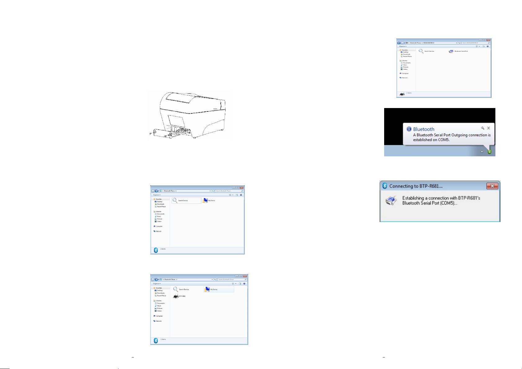
2. Search communication port
In the interface of Figure 4, double-click the searched
“BTP-R681” icon, the BlueTooth software
will search the BlueTooth communication
port automatically.After the search ends, the
interface in Figure 5 will show.
III Installation of interface module
Take BTP-R681 as an example. Ensure that
the power of the printer is off and connect as
shown in figure 2. Plug the interface module
into the printer according to the arrowhead and fix them
Figure 2
with screws.
IV Connecting method
Take BTP-R681 as an example. The JK-B02
BlueTooth interface module has been
installed onto the printer. The BlueTooth
adapter has been inserted in the host
computer and the host computer has
installed the BlueTooth driver matching with Figure 3
the adapter.After powering on the printer and
the BlueTooth of host computer starts, the interface
in Figure 3 will show.
1. Search printers
Figure 5
3. Connect communication port
In the interface of Figure 5, doubleclick the searched “BlueTooth Serial
Port” icon and then the BlueTooth
communication between host computer
and printer will be built (see Figure 6). Figure 6
4. Connect communication port successfully
After connecting the communication
port successfully, the prompt in Figure 7
will show at the lower right corner of
the screen. At the same time, the color
of BlueTooth icon will become green from blue. Figure 7
V Realizing functions
After operating according to the above steps successfully, then we can carry out the
BlueTooth serial port connection between host computer and printer and carry out
various operations on the printer.
In the interface of Figure 3, double-click the
“Search Devices”. After finishing the search,
the icon of “BTP-R681” printer will show (see
Figure 4).
Figure 4

FCC STATEMENT :
This device complies with Part 15 of the FCC Rules. Operation is subject to the following
two conditions:
(1) This device may not cause harmful interference, and
(2) This device must accept any interference received, including interference that may
cause undesired operation.
Warning: Changes or modifications not expressly approved by the party responsible for
compliance could void the user's authority to operate the equipment.
NOTE: This equipment has been tested and found to comply with the limits for a Class B
digital device, pursuant to Part 15 of the FCC Rules. These limits are designed to provide
reasonable protection against harmful interference in a residential installation. This
equipment generates uses and can radiate radio frequency energy and, if not installed
and used in accordance with the instructions, may cause harmful interference to radio
communications. However, there is no guarantee that interference will not occur in a
particular installation. If this equipment does cause harmful interference to radio or
television reception, which can be determined by turning the equipment off and on, the
user is encouraged to try to correct the interference by one or more of the following
measures:
Reorient or relocate the receiving antenna.
Increase the separation between the equipment and receiver.
Connect the equipment into an outlet on a circuit different from that to which the receiver
is connected.
Consult the dealer or an experienced radio/TV technician for help.
RF warning statement:
The device has been evaluated to meet general RF exposure requirement. The device
can be used in portable exposure condition without restriction.
IMPORTANT NOTES
Co-location warning:
This transmitter must not be co-located or operating in conjunction with any
other antenna or transmitter.
OEM integration instructions:
This device is intended only for OEM integrators under the following
conditions:
The antenna is integrated and the transmitter module may not be co-located
with any other transmitter or antenna. The module shall be only used with
the antenna(s) that has been originally tested and certified with this module.
As long as 3 conditions above are met, further transmitter test will not be
required. However, the OEM integrator is still responsible for testing their
end-product for any additional compliance requirements required with this
module installed (for example, digital device emissions, PC peripheral
requirements, etc.).
Validity of using the module certification:
In the event that these conditions cannot be met (for example certain laptop
configurations or co-location with another transmitter), then the FCC
authorization for this module in combination with the host equipment is no
longer considered valid and the FCC ID of the module cannot be used on
the final product. In these circumstances, the OEM integrator will be
responsible for re-evaluating the end product (including the transmitter) and
obtaining a separate FCC authorization.
End product labeling:
This transmitter module is authorized only for use in device where the
antenna without any change. The final end product must be labeled in a
visible area with the following: “Contains Transmitter Module FCC ID:
2AEQL-JK-B02”.
Information that must be placed in the end user manual:
The OEM integrator has to be aware not to provide information to the end
user regarding how to install or remove this RF module in the user's manual
of the end product which integrates this module. The end user manual shall
include all required regulatory information/warning as show in this manual.
 Loading...