

Shakespeare Electronic SeaWatch STYLE 3015, SeaWatch STYLE 3019, SeaWatch STYLE 3004 User Manual
Page 1
STYLE 3019/3015/3004
OMNI-DIRECTIONAL MARINE TV/FM ANTENNA
Congratulations! You have chosen the Shakespeare Style 3019, 3015 or 3004 omni-directional TV/FM
antenna which bring the comfort of home onto the water, Anywhere!
By carefully following the installation and connection instructions, you will receive years of superior performance
from your new Shakespeare antenna.
Special note: Please familiarize yourself with the assembly and installation of the antenna by fully
reading and understanding these instructions before you begin.
Parts List
1 3019/3015/3004 Antenna
1 75Ω RG59 Cable x2 F-Connectors
1 1.5m Adapter Cable – fitted with F-Connector to TV
1 DC Wire
1 Power Supply (12v and 24v)
1 IEC-F Connector Boot
1 Power Adapter
2 Screws
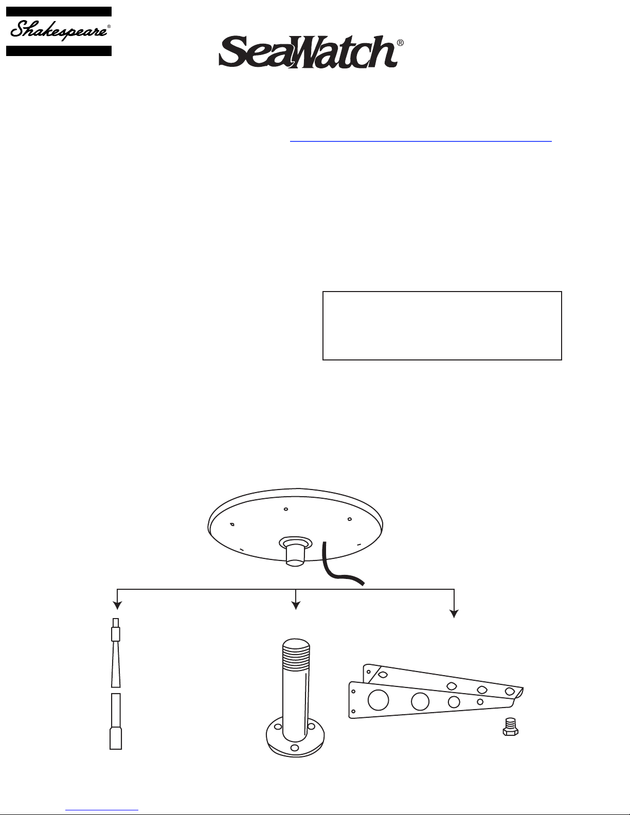
Antenna Mounting Instructions
Step 1
Mount antenna on a marine extension mast,
standard 1in-14 thread marine antenna mount of
sailboat mounting bracket as illustrated below.
TO PREVENT FIRE OR SHOCK HAZARD, DO
NOT EXPOSE POWER SUPPLY SECTION OF
THIS APPLIANCE TO RAIN OR MOISTURE.
When attaching the antenna to the antenna mount,
be very careful to start threads properly before
screwing antenna into position. If antenna mounting
socket and antenna mount are not aligned correctly,
the antenna mounting socket threads will become
crossed and eventually strip.
WARNING!
Caution!
Figure 1
4008 Marine Extender 4365 Straight Mount
4366 Sailboat Mounting Bracket
Some Modification May Be Needed
Page 2
Step 2
In a convenient
locations, mount the
two #6 screws vertically
3-1/4in apart leaving
#6 screws 3-1/4in
the screwheads approximately 1/8in from wall
or mounting surface.
Hand power supply
onto screws.
Step 3
Route the RG-59 cable from the antenna to this
power supply. Allowing enough cable slack for later
installation of F-connectors, cut the cable. Route
the remaining piece of RF-59 from the power supply
to the back of the TV.
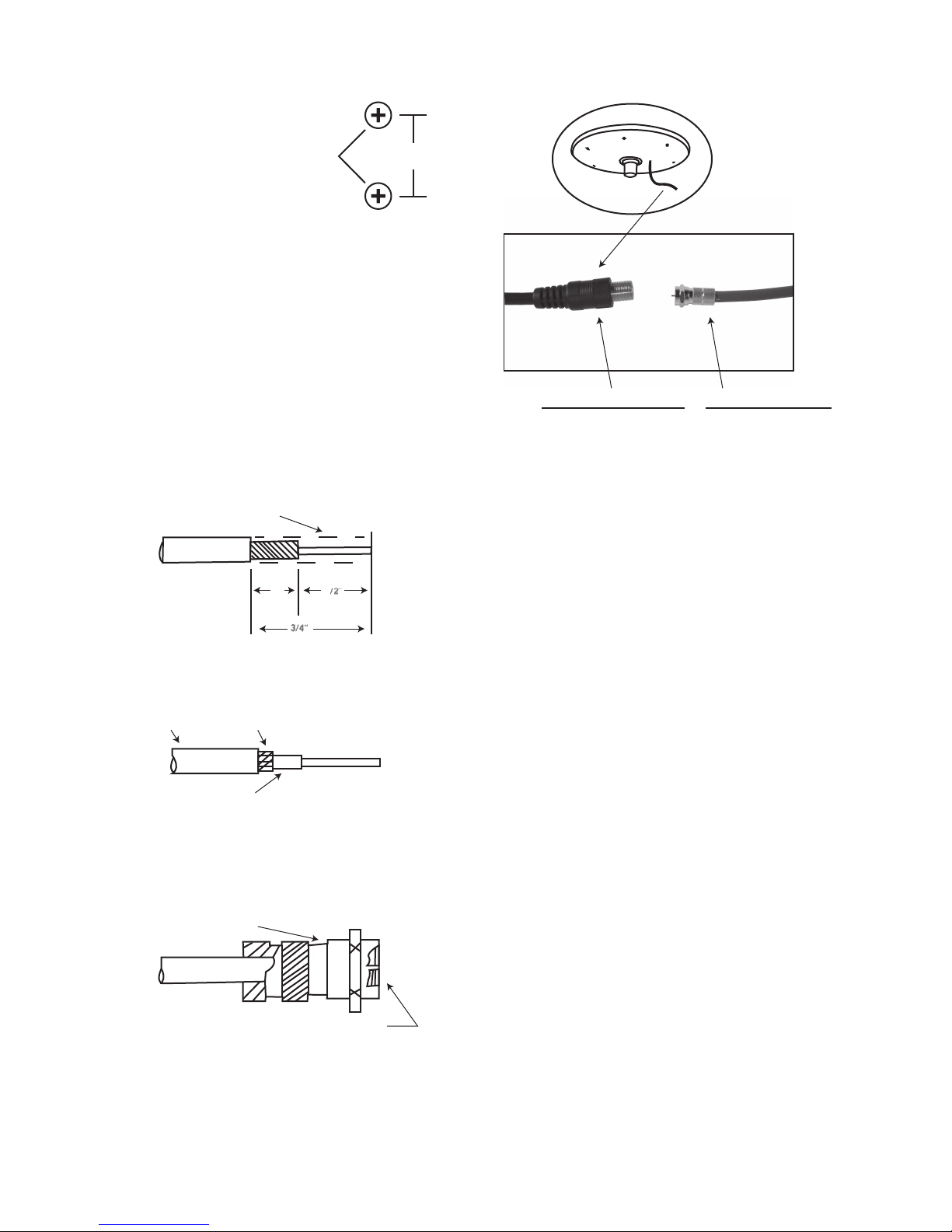
Step 4
To install F-connectors strip cable jacket. See
Figure 2A.
Pre-stripped
From Factory
Figure 2A
RG/59
½in¼in
¾in
Figure 3
Connect Female F-Connector to Male F-Connector
Step 5
Conenctor power supply kits. Connect the cable
from the antenna to the power adapter. Connect
the output connector of the power supply unit to the
DTV receivers or TVs. Connect the AC/DC adapter
to the 12V DC jack on the power supply unit and
plug the adapter into the power socket. Adjust the
gain in the power supply unit for best signal reception. See Figure 4.
Push back and twist the braid around the Dielectric
until it butts against the cable jacket. See Figure 2B.
Figure 2B
Jacket
RG/ 59
Dlelectric Center Conductor
Twist Braid
Screw the F-connector onto the cable jacket until the
Dielectric butts against the inner retaining ring. Cut
the center conductor off flush with the end of the
connector. See Figure 2C.
Type F-Connector
Figure 2C
RG/ 59
Center Conductor To Be Flush
With End Of Connector
Repeat this step to install all four type F-connectors.
Special note: Place boot on cable before installing
F-connector at the antenna.
Page 3

Figure 4
Powered from
12V AC/DC
Power Adaptor
DC 12V or 24V
+ -
Powered from
DC Battery
12V DC
Power Supply
TV ANT. in
Amplified Signal
TV 1 TV 2
Installation Recommendations
Minimum bend radius: 3in for RG-59 coax.
Tighter bends will cause shorts and change impedance.
Pulling Tension: 75lbs maximum. Leave no
tension on cable after it is installed.
Staples or clamps: The use of flat staples with
coax cable is damaging to the cable. Only round
headed staples should be used. Any clamps or
securing devices used with coax should grip the
cable evenly around the circumference without
crushing the cable.
Exposure to high heat: Maximum temperature
limit is 80°C (176°F). Keep cable away from heating
vents, engine compartments and engine exhaust
pipes.
Crushing: Coax should not be installed in a
manner that would allow it to be crushed. It should
not be “stuffed” or wedged into areas where the
cable could be pinched by the flexing of the boat hull
or cabin.
Page 4

Optional Accessories Available
4366
Sailboat Mast Mount
Aluminum sailboat mast
mount.
4365
Straight Mount
4in high 1in - 14
threads stainless
steel mount.
Perfect for radar
arches. May be
used with Style
4364 one foot
extension mast.
4364-B
Extension Mast
One inch diameter
extension mast for light to
moderate duty applica-
tions. While molded
polycarbonate male upper
and female lower 1in - 14
threads.
4711
Nylon Mount
1in, 2in nylon
mount. Low profile
 Loading...