

Page 1
STYLE 2025
OMNIDIRECTIONAL MARINE TV/FM ANTENNA
#12. INSULATED
QUICK-DISCONNECT
TERMINALS
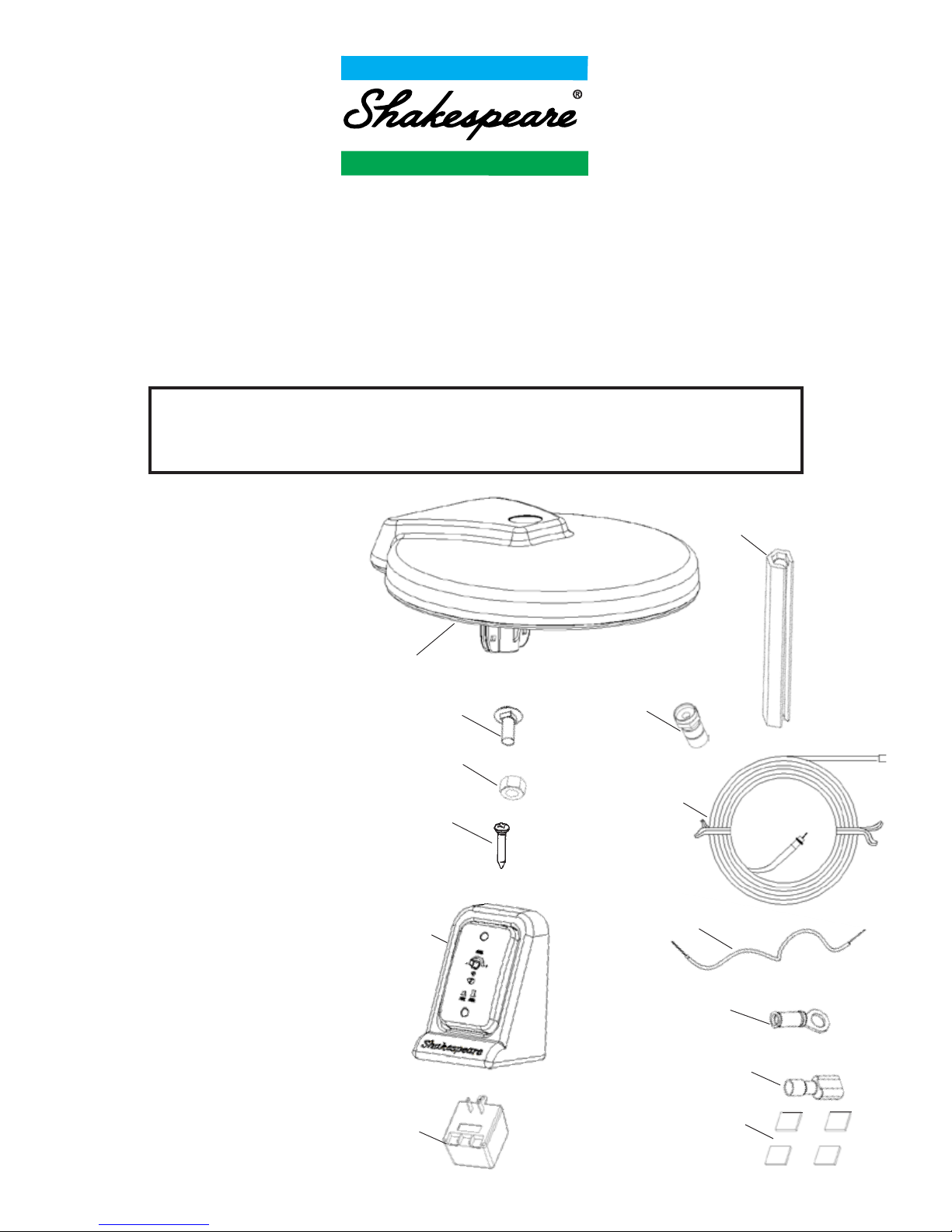
PARTS LIST
1. (1) Antenna
2. (1) 30' RG-59 Low Loss Coax Cable
3. (1) Cable Tool
4. (4) Twist-on Type F-Connectors
5. (1) 2025-CP Control Box
6. (1) Plug-in Transformer
Input: 120 VAC, 60 Hz
Output: 16 VDC, 140 ma
7. (1) 5’ 18 GA insulated wire
8. (4) #6 5/8” screws
9. (4) 1/4-20 Nylock Hex Nuts
10. (4) 1/4-20 Carriage Bolts
11. (2) Insulated Ring Terminals
12. (4) Insulated Quick-Disconnect
Terminals
13. (4) 1” Velcro Strips
WARNING!
To prevent FIRE or SHOCK HAZARD, avoid exposure of control
panel to moisture.
NOTE: Please read all instructions before beginning installation!
#1. ANTENNA
#3. CABLE TOOL
#4. TWIST-ON
F-CONNECTOR
#10. CARRIAGE BOLT
#9. NYLOCK HEX NUT
#2. COAX CABLE
#5. 2025-CP
CONTROL BOX
#11. INSULATED RING
TERMINALS
#6. PLUG-IN
TRANSFORMER
#13. VELCRO STRIPS
TOOLS NEEDED
#2 Phillips screwdriver
7/16” wrench
Crimping tool
Medium slot screwdriver
Cable tool (provided)
Wire stripper
#7. 18 GA INSULATED WIRE
#8. 5/8” SCREWS
Page 2
2. Pull the cable down until the end of the connector is
flush with the hex-shaped end of the cable tool. See
Figure 3.
3. Insert the cable tool with cable attached into the
mounting bracket on the underside of the antenna,
aligning the end of the connector with the cable
connection on the antenna. Push up until you feel a
SLIGHT resistance.
4. Turn cable tool to the right until the connector is
tight.
5. Remove cable tool.
INSTALLING ANTENNA ON MOUNT
1. After cable connection is made, slide antenna
onto mount. GENTLY pull back any extra cable.
2. Fasten antenna to mast using 1/4-20 carriage
bolts (#10) and nylock hex nuts (#9). Tighten
firmly to prevent antenna from turning on mount
or mast.
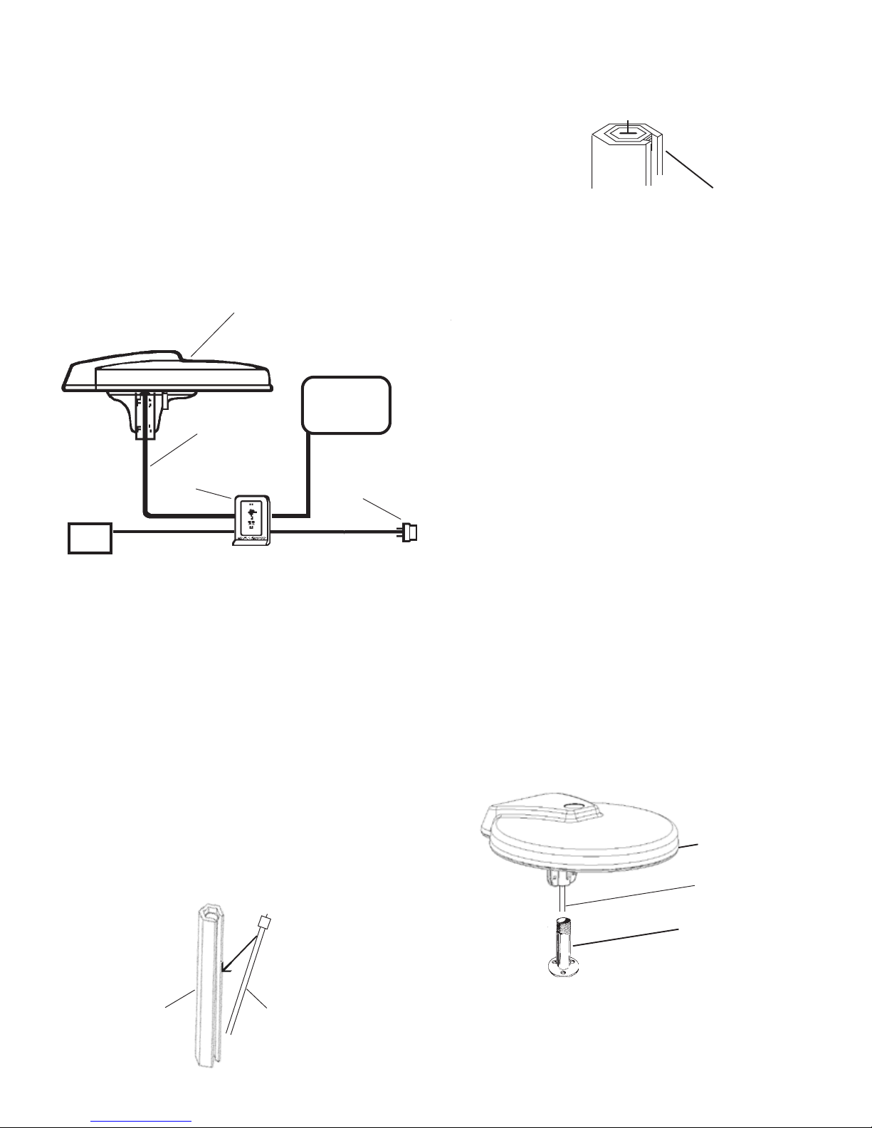
CONNECTING COAX CABLE TO THE ANTENNA
1. Slide coax cable into cable tool (#3) through
the slot in the side of the tool, hex end up. See
Figure 2.
INSTALLING ANTENNA MOUNT
1. Install an appropriate 1” diameter extension mast,
antenna mount or pipe.
2. Route cable (30’ RG-59 provided) from antenna
location to control box.
3. Attach F-connector (#4) to coax cable. See
instructions for installing connectors, page 4.
BEFORE YOU MOUNT ANTENNA:
Determine where you will put your control
box before mounting your antenna.
There are two options for installation of the control
box shown on page 3. A wiring diagram is shown in
Figure 1 to help you determine the location for your
control box and antenna. Where you mount your
antenna and install the control box determines
where and how you run your cables.
DO NOT begin installation before carefully reading
all installation instructions.
CABLE
TOOL
COAXIAL
CABLE
CABLE
CONNECTOR
FLUSH WITH
END OF
CABLE TOOL
FIGURE 2
FIGURE 1
ANTENNA
CONTROL
BOX
MOUNTS ON 1” DIAMETER PIPE
(Not provided)
COAX CABLE
(30’ PROVIDED)
ANTENNA
1” DIAMETER MOUNT
(Not provided)
SEE OPTIONAL
MOUNTS PAGE 4.
COAXIAL CABLE
FIGURE 4
PLUG IN
TRANSFORMER
REQUIRES
117 VAC
2
18 GA WIRE
REQUIRED
(5’ PROVIDED)
TV
18 GA WIRE
REQUIRED
(NOT PROVIDED)
12-24 vDC
Source
+ -
Page 3

MOUNTING THE CONTROL BOX:
You have two options:
OPTION A: Set Top-Mounted
Secure the control box using the
velcro strips (#13) provided.
OPTION B: Flush-Mounted
Detach wall plate from control box case.
Cut hole in wall large enough to accommodate the cable connections. Pull cables and
power wires through wall.
CONNECTING CONTROL BOX
Connections on the back of the control box are clearly
marked.
WARNING
DO NOT CONNECT TO BOAT’S AC OR DC POWER
SUPPLY until all other connections on the control
box are completed.
1. The 5 ft.18 GA power wire (#7) provided has a + (red)
wire and - (black) wire. Crimp ring terminals (#11) on
one end of power wire. Connect two insulated quickdisconnect terminals (#12) to other end. Connect the
end with the quick-disconnect terminals to the back of
the control box, EXACTLY AS SHOWN in Figure 5.
Connect the end with the ring terminals to the appropriate + (red) and - (black) terminals on the 117 VAC
plug-in transformer (#6), Figure 5.
RED
BOAT BATTERY
12-24 vDC
PLUG-IN
TRANSFORMER
18 GA WIRE
(not provided)
18 GA WIRE
(5 ft. provided)
RG-59 COAX
CABLE
(30 ft. provided)
FROM SHORE CABLE
TV ON VCR AUXILIARY
COAXIAL CABLE
(not provided)
BLACK
2. There are three coax cable connections on the back of
the control box — Antenna, TV Set and Auxiliary (for
cable, VCR, satellite, etc.). Attach cable from antenna
to the antenna connector on the control panel. If an
auxiliary source will be used, connect it now. Connect
the TV cable to the back of the control panel. See
Figure 5 for correct connections.
3. To connect a 12-24 vDC power source to the back of
the control box, install two (#12) quick disconnect
terminals on an 18-ga. insulated wire (not provided).
Be sure to observe correct polarity when making
these connections. See Figure 5.
NOTE: Power switches automatically between 117
volts AC (wall power source) and 12-24 volts DC (boat
battery) as needed.
4. Plug transformer into AC receptacle. Use the
receptacle cover plate screw to secure the transformer to the AC receptacle.
5. For antenna reception, push in the On/Off button
on the front of the control panel. The Red LED will light
on the control panel and on the bottom of the antenna.
For auxiliary reception, the button should be out.
No red light on control panel or antenna.
6. Turn on the TV. If you have a weak signal, turn the
gain knob on the front of the control panel
clockwise (up). If you have a strong signal, turn
counterclockwise (down). Use the least amount
of gain necessary for good reception.
3
FIGURE 5
RED
On/Off
Gain
Positive and
Negative leads
from Battery and
Transformer must
be connected to
the control box
terminals exactly
as shown
IMPORTANT
BLACK
Page 4

Pull back braid over jacket.
Make sure no braid
touches center conductor.
Figure B.
Screw the F-connector onto
the cable jacket until the
center conductor extends
1/8” past end of connector.
Figure C.
To install the F-connectors,
strip the ends of the RG-59
cable as shown in Figure A.
(Note the ends of the original
30' cable have been factory
pre-stripped for convenience.)
Figure A
Figure B
Figure C
Minimum Bending Radius: 3" for RG-59. Tighter bends
will cause shorts and change impedance.
Pulling Tension: 75 pounds maximum. Leave no
tension on cable after it is installed.
Staples or Clamps: The use of flat staples with coax
cable is damaging to the cable. Only round headed
staples can be used. Any clamps or securing devices
used with coax should grip the cable evenly about the
circumference without crushing the cable.
Exposure to High Heat: Maximum temperature limit is
176° F (80° C). Keep cable away from heating vents,
engine compartments and engine exhaust pipes.
Crushing: Coax should not be installed in a manner that
would allow it to be crushed. It should not be stuffed or
wedged into areas where the cable could be pinched by
the flexing of the boat hull or cabin
.
Exposure to Moisture: The cable jacket will withstand
most outdoor environments. However, connections and
splices must be sealed against water entry.
HOW TO INSTALL F-CONNECTORS ON CABLE
for female or extend for male
4358
FM Take-off
Designed to provide FM radio signals
from TV antenna. The 4358 may be
attached anywhere in the downlead
cable and will not interfere with regular TV
reception.
4330
30' RG-59 low loss, marine
type, coaxial TV cable.
4360-B
50' RG-59 low loss, marine
type, coaxial TV cable.
4364
1’ Extension Mast
One inch diameter extension mast for
light to moderate duty applications. White
molded polycarbonate male upper and
female lower 1" - 14 threads.
4365
Straight Mount
4" high 1"-14 thread stainless steel mount.
Perfect for radar arches. May be used with
Style 4364 one foot extension mast.
TV-1060
Screw-on "F" type Connector
No soldering or crimping required. Two per pack.
FS-8101
"F" type Barrel Connector
Use with two TV-1060 "F" connectors to form a
secure RG-59 cable splice.
TV-1024
Connector
Surface mounted flip-open “F” pass-through
connector. Attaches to any flat surface
providing an easy connection for coax
cables when needed, and closing out the
environment when not in use.
4700
Stainless Steel Extension Mast
Heavy-duty stainless steel extension mast with
standard 1”-14 thread male and female fittings. 6” long.
4700-1
Stainless Steel Extension Mast
Heavy-duty stainless steel extension mast with
standard 1”-14 thread male and female fittings. 1’ long.
4700-2
Stainless Steel Extension Mast
Heavy-duty stainless steel extension mast with standard
1”-14 thread male and female fittings. 2’ long.
RECOMMENDATIONS FOR INSTALLING CABLE
6111 Shakespeare Rd., Columbia, SC 29223 · 803-227-1590 · Fax: 803-419-3099
www.shakespeare-marine.com
 Loading...