

Page 1

Owner’s Manual
For Soundhole diameter
SH PFC-W: 3¼ to 3½ in [83 to 88mm]
SH PFA-W: 3.8 to 4.2 in [96 to 106mm]
SH PFA-W / SH PFC-W
SH PRC-W
PanaFlex Wireless
Transmitter System
for
Acoustic or Classic Guitars
V3 2013-07-19
Page 2

SHADOW PANAFLEX WIRELESS Owner’s Manual ENGLISH
Contains FCC ID:
QLPSAM88
MIC ID:
204-320137
Indoor use
WEEE
Reg. Nr.: DE 42527131
Thank you very much for your interest in our products!
Before you power on the unit, please take the time to carefully read this manual to learn how the system works. You must read all
safety instructions to ensure proper handling. If you still have additional questions, please feel free to ask us.
http://www.shadow-electronics.com
Safety Instructions
Read and follow all instructions. Keep this instruction and heed all warnings!
Refer all servicing to qualified service personnel. Servicing is required when the apparatus has been damaged in any way, such as power-supply
cord or plug is damaged, liquid has been spilled or objects have fallen into the apparatus, the apparatus has been exposed to rain or moisture,
does not operate normally, or has been dropped
Never open or damage the battery. Follow the safety instructions about handling
WARNING: To reduce the risks of fire do not expose this apparatus to rain or moisture.
Do not use this system near a heart pace meter or other sensitive electronics. (E.g. Airplane, Transmitter, Hospital)
Any unauthorized changes or modification will immediately void the warranty.
This unit complies all technical requirements of FCC and CE.
Safety Instructions for Lithium Ion Battery
Do not disassemble or modify the battery pack. The battery pack is equipped with built-in safety/protection features. Should these features be
disabled, the battery pack can leak acid, over-heat, emit smoke, burst and/or ignite.
Do not connect the positive (+) and negative (-) terminals with a metal object such as wire.
Do not discard the battery into fire or heat it. Otherwise its gas release vent or safety features will be damaged and/or its electrolyte can ignite,
possible leading to acid leakage, over-heating, smoke emission, bursting and/or ignition on it.
Do not immerse the battery in water or seawater and do not allow it to get wet. Otherwise, the protective features in it can be damaged, it can
be charged with extremely high current and voltage, abnormal chemical reactions may occur in it, possibly leading to acid leakage, smoke
emission, bursting and/or ignition, inhibiting recharging, or can damage the built-in protective features, causing it to be charged with an
extremely high current and voltage and, as a result, abnormal chemical reactions can occur in it, possible leading to acid leakage, over-heating,
smoke emission, bursting and/or ignition.
FCC Declaration
This device complies with Part 15 of the FCC Rules. Operation is subject to the following two conditions:
(1) this device may not cause harmful interference, and
(2) this device must accept any interference received, including interference that may cause undesired operation.
Changes or modifications not expressly approved by the party responsible for compliance could void the user's authority to operate the
equipment.
The device for the band 5150-5250 MHz is only for indoor usage to reduce potential for harmful interference to co-channel mobile satellite
systems.
This equipment generates, uses, and can radiate radio frequency energy and, if not installed and used in accordance with the instruction
manual, may cause harmful interference to radio communications. Operation of this equipment in a residential area is likely to cause harmful
interference in which case the user will be required to correct the interference at his/her own expense.
CE Mark Warning
This equipment complies with the requirements relating to electromagnetic compatibility, EN 55022 class A for ITE, the essential protection
requirement of Council Directive 89/336/EEC on the approximation of the laws of the Member States relating to electromagnetic compatibility
Company has an on-going policy of upgrading its products and it may be possible that information in this document is not up-to-date.
Please check with your local distributors for the latest information. No part of this document can be copied or reproduced in any form without
written consent from the company
WEEE
Information on Disposal for Users of Waste Electrical & Electronic Equipment:
This symbol on the product means that used electrical and electronic products should not be mixed with general household waste. For proper
treatment, recovery and recycling, please take this product to designated collection points where it will be accepted free of charge.
Alternatively, in some countries you may be able to return your products to your local retailer upon purchase of an equivalent new product.
Disposing of this product correctly will help save valuable resources and prevent any potential negative effects on human health and the
environment, which could otherwise arise from inappropriate waste handling.
Please contact your local authority for further details of your nearest designated collection point.
Penalties may be applicable for incorrect disposal of this waste, in accordance with you national legislation.
Information on Disposal in other Countries outside the European Union
WEEE: This symbol is only valid in the European Union. If you wish to discard this product please contact your local authorities or dealer and
ask for the correct method of disposal.
© Shadow Elektroakustik, Peter-Haendel-Str. 2, DE-91334 Hemhofen / Germany Page 2/6
Page 3
SHADOW PANAFLEX WIRELESS Owner’s Manual ENGLISH
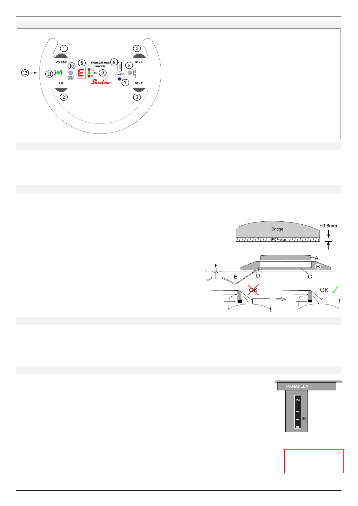
Panaflex Transmitter
B VOLUME Control
C PAN: Panorama control
D BT-T: Combined BASS / TREBLE control for the upper strings
E BT-B: Combined BASS / TREBLE control for the lower strings
F WIRELESS ON/OFF: ON/OFF switch and PHASE reverse switch
G MINI-USB Input to charge the battery
H CHARGE LED: 3 color charge control LED
I TUNER: Tone display
J TUNER: Control-Leds
K TUNER ON/OFF switch and PAIRING switch
L LED: 3 color operation control LED
M From the side: Battery compartment
N From the bottom: Connector for the stereo Nanoflex pickup
Fig. 1
Fig. 2
Fig. 3
When handling with
LI-ION batteries read the
safety instructions first!
Fig. 4
Controls of the Transmitter
Accessories
• Panaflex (Stereo Nanoflex) pickup (Acoustic or Classic), applicable with installation material
• Stereo Panaflex Preamp / Transmitter (PFA-W: Acoustic or PFC-W: Classic) with installation material to fit different soundholes
• 5V USB Charger with two USB cables (Type A to Micro B)
• Stereo Panorama Receiver: PRC-W
Installing the stereo Nanoflex pickup
• Remove the original saddle and drill a 3.1mm diameter hole in the corner of the saddle slot at the bass string side (see Fig. 2 D)
• The hole has to be drilled in an angle of 30°-45°. Check your bracing before drilling the hole to avoid damage.
• Clean up the saddle slot and eliminate the wood dust and chips. Lead the NFX pickup through the hole (D) in the bridge and place
it into the bridge (C) slot showing “NFX top” up towards the saddle.
• Fig. 1: To accommodate the height of the original bridge reduce the height of the
saddle. The thickness of the Nanoflex is around 0.8mm.
• Important: The bottom side has to be absolutely flat!
• Insert the saddle and secure it temporarily with a piece of tape.
• Fig. 2: Use the single wire clip (F) (if supplied) to secure the wire from
the pickup to the underside of the top and secure the cable into it.
Failing to secure the wire may produce feedback and other bizarre
audio consequences. Also fix area (E) to avoid noise or feedback.
• Connect the 3-pin cable of the pickup to the bottom of the transmitter.
• Fig. 3: During reassembling the strings, pay attention to the saddle! If
needed press it back to the correct upright position. Otherwise it is easy
to cause feedback!
Installing the Panaflex transmitter
• Use the adhesive foam strips to increase the diameter of the transmitter. For best results it should be neither too loose nor too
tight. If it is too tight, you may damage the sound hole or of your guitar other part. It is too loose the transmitter may fall off
during playing.
Don’t forget: Before you finally insert the transmitter plug in the 3-pin connector from the stereo Nanoflex pickup into the connector located on
the bottom of the transmitter!
Inserting / changing the LI-ION battery
The transmitter uses a very common and easy to get rechargeable 3.7V Lithium Ion battery (E.g.NP60)
Replace or change the battery if the capacity drops down or the battery cannot be recharged
anymore.
• Remove the transmitter from the guitar sound hole. Fig.4: Open the battery holder (A) - located on
the side - by pressing the wings together. Now you can remove or slide in the battery.
• When inserting the battery take care to point to the contacts inside the transmitter. Also make sure
the contacts (Fig.4: B) looking down, same as the contacts inside the battery compartment.
If you insert the battery in any other way the unit cannot operate.
• Close the battery compartment to fix the battery in place.
• The battery has a capacity of ~1050mA/h. Depending on the state of the technology the value may vary
from 1000mA/h up to 1200mA/h or similar. The transmitter uses approx. 200mA per hour.
Just divide the values to estimate how long the battery may last: Example: 1050 / 200 = 5¼ hours
• The full capacity of the battery may not reach if the environment temperature is extremely low or high.
• Use normal room temperature to operate or charge.
• You can always recharge the battery, even it is not empty. LI-ION batteries don’t have the “Memory Effect” like N-Mh batteries!
© Shadow Elektroakustik, Peter-Haendel-Str. 2, DE-91334 Hemhofen / Germany Page 3/6
Page 4
SHADOW PANAFLEX WIRELESS Owner’s Manual ENGLISH
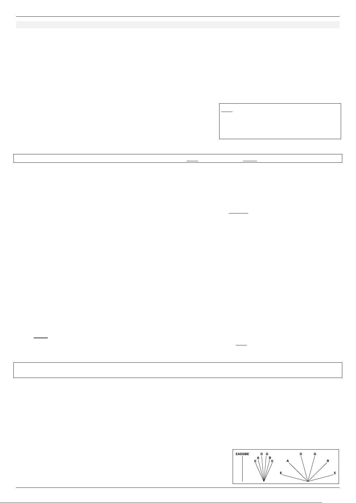
Note:
If the battery is full, the mode may alternate between
“Fast Charge Mode” and “Done”
During charging the unit will be switched off
automatically!
Fig. 5
Battery Low Warning
The voltage of the battery will be periodically checked. Below a certain level – which means the battery capacity is diminished – the
red part of the LED L starts to flash slowly. After further dropping of the battery voltage, which mean the capacity will be off
shortly, the red part of the LED L starts to flash fast. Then you should recharge the battery soon.
• CHARGING: Before you can use the unit the first time charge the battery as follows:
o Connect the USB cable between the charger and the USB socket G of the transmitter.
o Or alternative: If the receiver is connected to the USB charger (Yellow LED is on) connect the 2nd USB cable between USB
socket E of the receiver and the USB socket G of the transmitter.
o Note: Connecting the Charger switches the transmitter off!
o Charge time may be up to ~6 hours. This depends on the overall condition of the battery.
• The CHARGE LED H shows the state of charging:
o White: PRE CHARGE MODE (Depends on the battery’s capacity)
o Purple: FAST CHARGE MODE
o Cyan: DONE
o Blue: ERROR: E.g. Battery missing, short or defect or thermal error
CONTROLS
Note: The tact switches have double function: You can either press it for a short time or hold it for a longer time (~1 sec.)
• LED Info: The LED L indicates several different modes.
• SWITCH ON: NORMAL PLAY MODE
o Press the switch WIRELESS ON/OFF F, to switch the unit on. This activates RF transmitting too
o Blue shows the wireless connectivity: Blink: No connection. On: Connection established.
• SWITCH ON: TUNER ONLY MODE
o Press the switch TUNER ON/OFF K, to switch the unit on (TUNER ONLY MODE) without transmitter function
o To switch it off again hold the switch TUNER ON/OFF K or WIRELESS ON/OFF F for a longer time (~1 sec.)
o If the tuner is not in use (no input signal) for ~90 sec. the transmitter switches off automatically!
• SWITCH OFF:
o Press and hold (~1 sec.) the switch WIRELESS ON/OFF F, to switch the unit off.
• TUNER IN NORMAL PLAY MODE ON
o Press the switch TUNER ON/OFF K, to start the tuner operation. This mutes the analog output of the receiver
o The display shows the note played and both LEDs HI or LO showing how close it is to the correct pitch. If you reached the final
pitch the LED OK lights up
• TUNER OFF
o Press the switch TUNER ON/OFF K, to end the tuner operation. If the tuner is not in use (no input signal) for ~90 sec. the
display will be switched off. This is shown by a flashing dot of the display
• PAIRING: For first time use or if you want to operate a transmitter with a different receiver you need to “pair” these as follows:
o 1st on the Receiver: If the system is not paired the PAIRING LED O flashes slow. Now press the switch PAIRING N for around
½ sec. The blue PAIRING LED O starts to flash faster. After successful pairing the blue LED will be on steady.
o Note: You have ~15 sec. time to pair a transmitter to the receiver! Otherwise you must start the pairing process again.
o 2nd on the Transmitter: After starting the pairing process on the receiver press and hold (~1 sec.) the switch
TUNER ON/OFF K. This starts the pairing function of the transmitter.
o The LED L flashes alternating red and green. After a successful pairing the blue element of the LED L will be on steady.
Blue flashing of the LED L or PAIRING LED C on the receiver indicate that there is no communication between transmitter and receiver. This
may possible if the system is not paired, or the distance between transmitter and receiver is too long or the occurrence of any other trouble.
• PHASE: Depending on the environment some feedback - which means awkward sound on one frequency - may occur. This has a
physical background and depends on the position between your instrument and speaker. A good method to lower the risk of
feedback is to turn the phase by 180° to change the physical conditions. Very often it helps, but sometimes it will support the
feedback or just change the frequency of the feedback. In this case switch the phase back and try to change your position.
o To change the phase press the switch WIRELESS ON/OFF just shortly
o Depending on the state of phase the LED L lights up GREEN or RED for a moment.
• VOLUME CONTROL:
o Turn the volume control to get your desired volume. We suggest not selecting too low levels for normal operation –
otherwise the “signal to noise ratio” is not as good
• PAN CONTROL:
o Controls the amount of effect between mono and stereo.
o See Fig. 5 for details
o For stereo operation you must use a 2 channel amplifier (E.g. Mixer)
© Shadow Elektroakustik, Peter-Haendel-Str. 2, DE-91334 Hemhofen / Germany Page 4/6
Page 5
SHADOW PANAFLEX WIRELESS Owner’s Manual ENGLISH
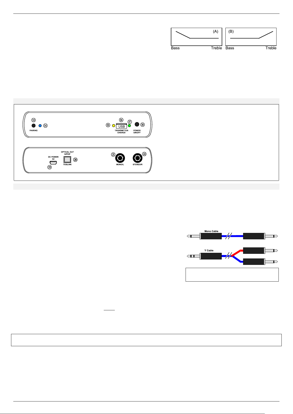
Receiver
Front view
Back view
N PAIRING Tact switch
O PAIRING LED
P CHARGE LED
Q CHARGE USB Socket
R POWER ON/OFF LED
S POWER ON/OFF Switch
T MINI-USB 5V Charger socket
U S/PDIF optical audio output for recording
V MONO/L Output for Mono or the left channel
W STEREO/R Output for Stereo or the right channel
*1TS: Tip, Sleeve of a ¼” mono plug
*2TSR: Tip, Sleeve, Ring of a ¼” stereo plug
Fig. 6
• BT-T CONTROL: To control the tone for the lower treble strings [G-B-E]. It works like a bass/treble rocker:
o Middle position: Flat sound
o Fig. 6: If you turn the pot away from the center positions either bass
or treble increases.
If bass is increasing (A) the treble will stay flat!
o Same if you increase treble (B): Bass will stay flat
• BT-B CONTROL:
o Same function as BT-T control but controls the sound for the upper strings [E-A-D]
• OVERLOAD: The transmitters ADC detects overloaded input signals.
o If the input is too high (E.g. heavy strumming) the LED L lights up with all colors, when linked = white for a moment.
Startup the Panorama Receiver
Controls of the Panorama Receiver
Connections
• POWER: Connect the USB cable (type A to MICRO B) between USB Charger and the rear USB socket T of the receiver.
o The yellow LED P lights up and you can use the front USB socket Q to charge the transmitter.
• POWER ON/OFF:
o Push the switch POWER ON/OFF S to switch the receiver on or OFF.
o The green LED R lights up. If equipped, the red SHADOW logo on the front will light up too.
• AUDIO OUTPUT: You have 3 options:
o MONO OPERATION: Connect a “Mono Cable” (TS*1 plug) between jack V
and an amplifier (E.g. mixer or guitar amplifier)
o STEREO OPERATION with “2 Mono Cables”: Connect two cables (TS plug)
between jack V and W and two channels of your amplifier. (E.g. mixer)
o STEREO OPERATION with a “Y-Cable”: Connect the stereo plug (TSR*2 plug)
to the jack W, the opposite ends (TS plug) to two channels of a stereo
amplifier. Set the channel 1 and 2 pan pots on the amplifier to the left and
right position!
• DIGITAL OUTPUT (S/PDIF): For digital reproduction connect an optical TOSLINK cable (not provided) between the TOSLINK
output U and your device. First remove the dust cap before you insert the TOSLINK cable. Note that this is the real digital output
signal without Volume, Pan Mute, and BT-T, BT-B control settings. This is best for reworking the digital signal with your audio
software (not provided) on the computer. Note: The S/PDIF is affected with a slight pre-emphasis from the transmitter side!
• USING other transmitter with the receiver: You always can setup another Shadow transmitter of the same family with the
receiver. Just follow the instruction for PAIRING. Note: A receiver can play the actual paired transmitter only!
Note: When you switch the receiver off and on again, it needs a little time until the settings of the transmitter are transferred to the receiver.
During this time you may hear the previous setting shortly before it changes to the new settings. This is normal and not a malfunction!
Special Functions
This system has an intelligent Frequency-Selecting-Procedure. Depending on the environment it searches for the best RF channel.
This works on 3 different frequency bands: 2.4GHz, 5.2GHz and 5.8GHz. In some countries 5.2 and/or 5.8GHz are not allowed. For
this you can deselect these frequency bands. This system has FCC and CE certificates to use all 3 bands in the US and Europe. For
Japan we offer a special version to meet Japanese requirements. It is possible that RF regulations in your country may vary after
printing this manual. In case you need updated information please visit our website for the latest manuals.
© Shadow Elektroakustik, Peter-Haendel-Str. 2, DE-91334 Hemhofen / Germany Page 5/6
Page 6
SHADOW PANAFLEX WIRELESS Owner’s Manual ENGLISH
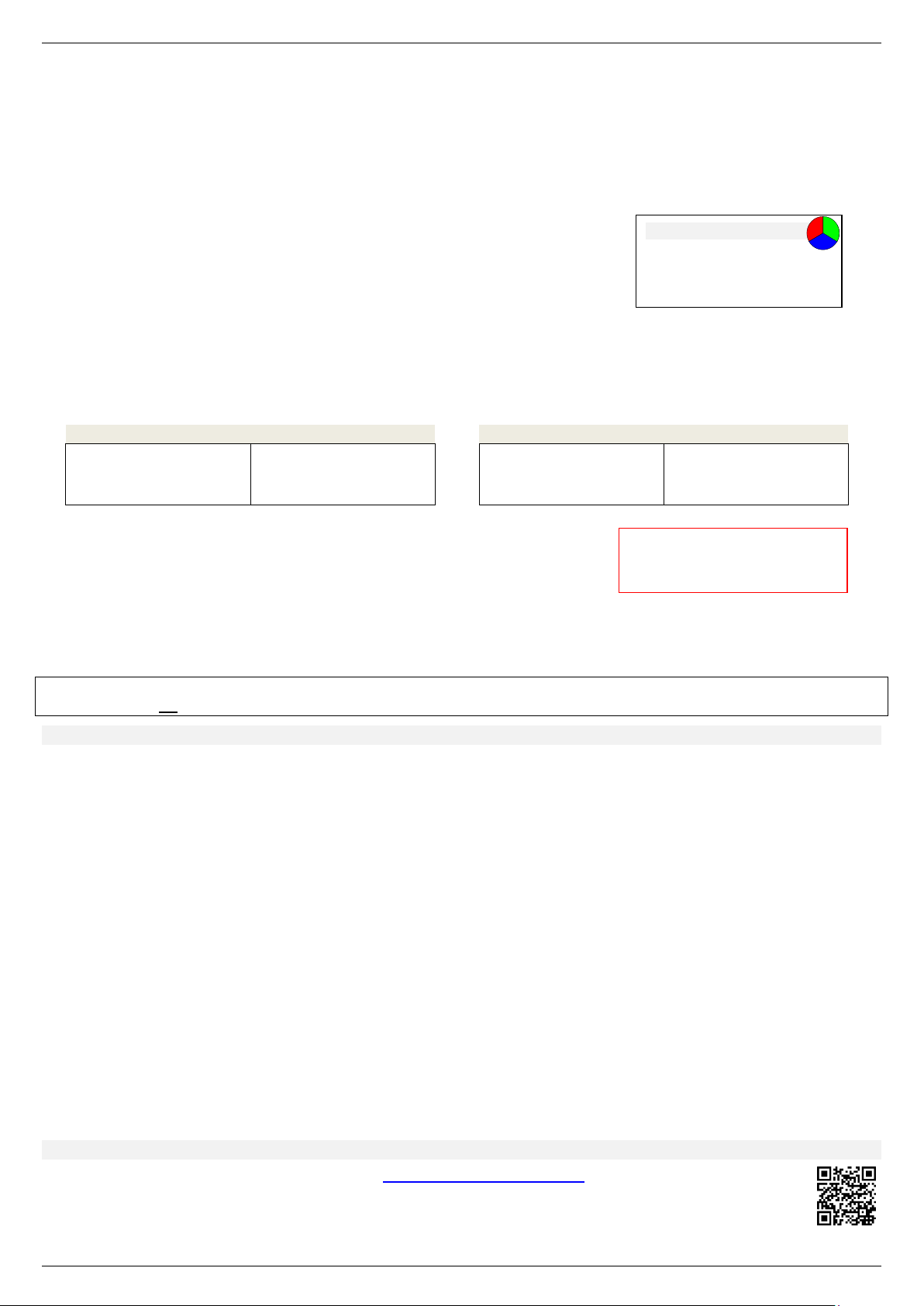
USA / EUROPE
JAPAN Version only
1. White = 2.4 + 5.2 + 5.8 *3
2. Red = 2.4
3. Yellow = 2.4 + 5.2
4. Purple = 2.4 + 5.8
5. Cyan = 5.2 + 5.8
6. Green = 5.2
7. Blue = 5.8
1. White = 2.4 + 5.2 *4
2. Red = 2.4
3. Yellow = 2.4 + 5.2
4. Purple = 2.4
5. Cyan = 5.2
6. Green = 5.2
7. Blue = 2.4
*3 Default (Allowed in USA and Europe)
*4 Default (Allowed in Japan)
LED Colors
Cyan = Blue and Green
Yellow = Green and Red
Purple = Red and Blue
White = Red, Green and Blue
*OBEY THE LAWS AND RULES
IN THE COUNTRY YOU WANT
If you need to select or deselect frequency bands, first you have to set the transmitter to the SERVICE MODE:
• ENTER SERVICE MODE:
o The transmitter must be switched off first, then press the switch Tuner K to start the TUNER ONLY MODE.
o Press and hold both Wireless ON/OFF F AND Tuner K at the same time (for ~1 sec.) to enter the SERVICE MODE.
o The LED L indicates this by alternate flashing between green and red.
• SHOW VERSION + BATTERY STATE: In the SERVICE MODE press the switch Wireless ON/OFF F:
o Display (Blink code) of the hardware version, followed by the battery charge state: (lights up for ~4 sec.)
Blue = Very good condition
Cyan = Good
Green = Normal
Yellow = Weak
Red = Very weak
After showing the transmitter is back in the SERVICE MODE.
• SELECT THE FREQUENCY BAND*:
o First select the SERVICE MODE than press switch Tuner K. The LED L flashes fast and shows the actual frequency selection.
o With the switch Wireless ON/OFF F you can walk (7 steps) through the selection as follows:
o After you set the desired selection, press the switch Tuner K again.
The selection is stored and the transmitter is back to the SERVICE MODE.
• QUIT SERVICE MODE:
o Press and hold the switch Wireless ON/OFF F to switch off the unit.
• INVOKE TEST MODE: Note: For test and service only!
o First select the SERVICE MODE.
o Again press both switches Wireless ON/OFF F AND Tuner K at the same time (for ~1 sec.) to invoke the TEST MODE. Now
the receiver changes it sound settings automatically controlled by the transmitter.
o After execution the transmitter switches back to the SERVICE MODE
RESET: In case of trouble you can reset the system by removing the battery for some seconds.
This will not change the Frequency Band selection!
TECHNICAL DATA
• Power Supply / Charger 100-240VAC 50/60Hz 5V/1.0A switching adapter *5 with 3 power adaptors for US, UK, and Europe.
Output socket: USB type A. You can use any other standard 5V USB source to charge. (E.g. computer)
• USB Cable(s) USB type A to type Micro B
• 3.7V LI-ION Battery Commercial Lithium Ion battery: Like NP60 with a capacity of ~1100mA/h. Running up to 6 hours
• RF Frequency 2.4, 5.2 and 5.8GHz. Indoor use only! 5.2/5.8GHz can be switched off to fulfill the rules and regulation of
your country where you operate this system.
• Range approx. 100ft. (30m) – depends on the environment. WLAN devices may disturb proper operation
• Transmission 3 channel digital transmission. (2x dig. audio, 1x data)
• Input Stereo input for active acoustic or classic-Stereo Nanoflex with 3-pin connector. *6
• Audio 2 digital channels with 48kHz sampling frequency
• Output Impedance 6k
• ADC Max. 24-Bit Conversion, 114dB Dynamic Range, -105dB THD+N, Overflow Detection
• DAC Max. 24-Bit Conversion, 113dB Dynamic Range, -94dB THD+N, SNR 113dB
• Opt. Output S/PDIF, Toslink, Stereo, 16bit, 48kHz, I2S
• Latency time ca. 6.9ms. This is an additional distance between your instrument and speaker of 7½ft (2.3m) only!
*5During normal operation or charge operation you may notice a high tone out of the Charger. This is normal and not a malfunction!
*6 String spacing Acoustic pickup: 11mm – Classic pickup: 11.8mm
Additional Information about this product
• Update information may be found on our website: http://shadow-electronics.com
There you can find manuals in different languages too. E.g. in German!
© Shadow Elektroakustik, Peter-Haendel-Str. 2, DE-91334 Hemhofen / Germany Page 6/6
Errors and omissions excepted - Subject to change without prior notice!
 Loading...