

Shadin Avionics AIS-380 Installation Manual
AIS-380 FUEL FLOW ADAPTER
P/N: 833811-00
INSTALLATION MANUAL
MANUAL P/N: M833811-00
REV C
Shadin Avionics
6831 Oxford Street
St. Louis Park, MN 55426
USA
Sales: (800) 328-0584
Customer Service: (800) 388-2849
www.shadin.com

M833811-00 Shadin Avionics
INSTALLATION MANUAL
AIS-380 FUEL FLOW ADAPTER
Rev: C
P/N 833811-00
Page: 2 of 20
REV
DATE
APP’D/ERN
CHANGE
–
5/9/2013
RJW
Baseline Release
A
6/14/2013
1306/004
Sections for accuracy and incomplete system description added
B
11/24/2014
1411/002
Added DC Fuel Flow Installation Application
C
01/15/2019
1901/001
Updated Sections 1.2 and 1.5, Table 1, Figure 4
REVISION LOG
Shadin Avionics 6831 Oxford Street St. Louis Park, MN 55426 USA

M833811-00 Shadin Avionics
INSTALLATION MANUAL
AIS-380 FUEL FLOW ADAPTER
Rev: C
P/N 833811-00
Page: 3 of 20
Table of Contents
REVISION LOG 2
1 OVERVIEW 4
2 INSTALLATION 11
3 CONFIGURATION TOOL 12
4 ENVIRONMENTAL QUALIFICATION FORM (EQF) 19
5 INSTALLATION DRAWINGS AND INSTALL KIT PARTS LIST 20
Shadin Avionics 6831 Oxford Street St. Louis Park, MN 55426 USA
M833811-00 Shadin Avionics
INSTALLATION MANUAL
AIS-380 FUEL FLOW ADAPTER
Rev: C
P/N 833811-00
Page: 4 of 20
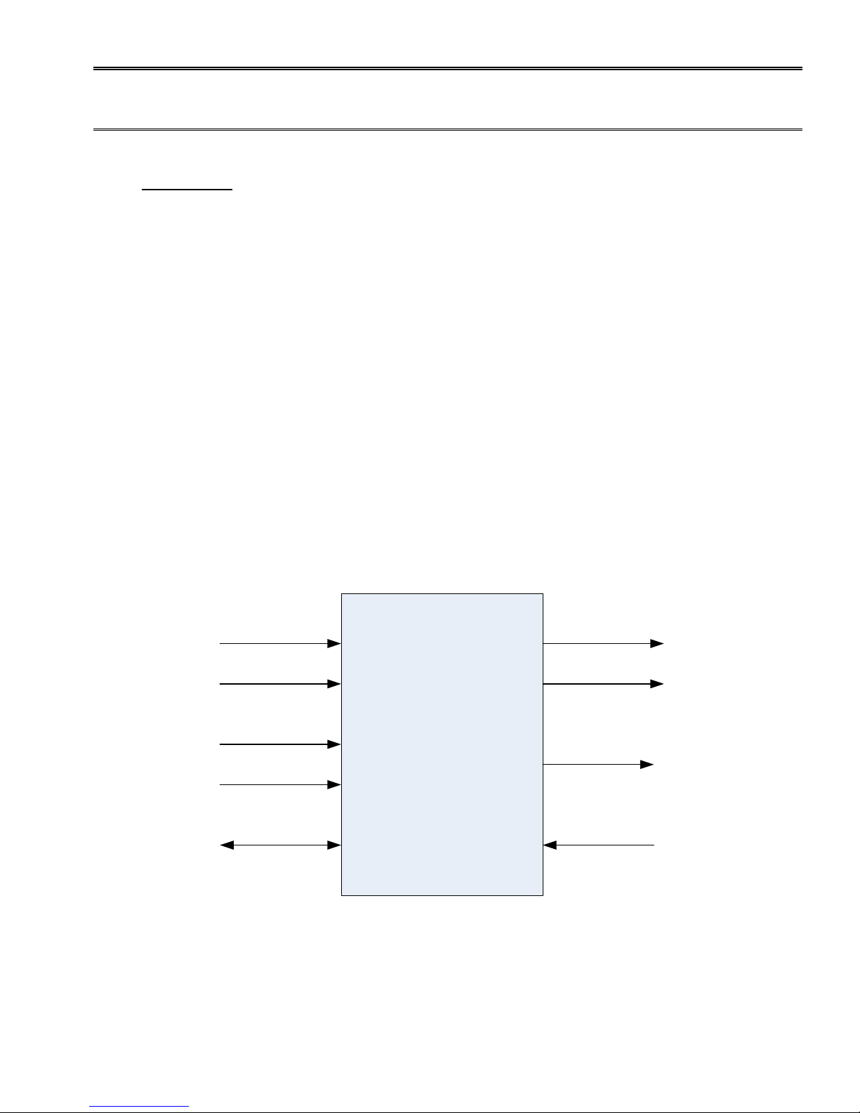
AIS
-380
Fuel Flow Adapter
ARINC 429
HS/LS Receiver 1
ARINC 429
HS/LS Receiver 2
ARINC 429
HS/LS Transmitter 1
ARINC 429
HS/LS Transmitter 2
SERIAL 1
RS-232
Maintenance
SERIAL 2
RS-232 Air Data/
Fuel Flow Data
Output
SERIAL 4
RS-422 Fuel Flow
Parameter Receiver
Pulse/Freq 1
Input
Pulse/Freq 2
Input
1 OVERVIEW
The information in this manual is subject to change without notification.
1.1 THE MANUAL
This manual is intended to determine a proper installation of the AIS-380 FUEL FLOW ADAPTER. Installation
instructions should be read and followed.
1.2 PRODUCT DESCRIPTION
The AIS 380 Fuel Flow is a product designed to provide fuel flow on a digital output bus to a display or GPS
receiver that can receive ARINC 429 or RS-232. The AIS Fuel Flow receives a digital frequency signal from a
fuel transducer or equivalent, ARINC 429 air data, and ARINC 429 heading. The AIS Fuel Flow combines this
data and re-transmits it on an ARINC 429 or RS-232 serial output bus.
The ARINC 429 speed, K-Factor, single/twin engine selection, fuel density, and serial output formats are
configurable using the PC based configuration tool referenced later in this installation manual.
There is an additional RS-422 receive port for a custom application designed specifically for the Bell 412 EPI
engine upgrade STC. This port will receive information regarding the fuel system from an ADIU (Advanced
Digital Interface Unit).
A basic overview is shown below in Figure 1.
Figure 1: AIS-380 Fuel Flow Adapter Overview
Shadin Avionics 6831 Oxford Street St. Louis Park, MN 55426 USA

M833811-00 Shadin Avionics
INSTALLATION MANUAL
AIS-380 FUEL FLOW ADAPTER
Rev: C
P/N 833811-00
Page: 5 of 20
The features which are applicable to all standard installations are listed below:
• Two +12 VDC power supplies are available for powering fuel flow transducers
• ARINC inputs are echoed to the ARINC outputs
• ARINC speed (high or low) is configurable. Each ARINC c hannel input and output speed is matched
when configured, e.g. ARINC channel 1 input channel set f or high speed res ults in ARINC c hannel 1
output set for high speed
• Fuel Flow labels 244 (Total Fuel Flow) and 347 (Left and Right independent Fuel Flow based on SDI)
are generated and output at an 8 Hz rate when conf igur ed f or nor mal fuel flow format on both ARINC
429 outputs
Specific features for the Bell 412 EPI Installation:
• Fuel Flow labels 351 (Left Fuel Flow) and 352 (Right Fuel Flow) are generated and output at an 8 Hz
rate when configured for Bell fuel flow format on both ARINC 429 outputs
• The AIS-380 accepts Bell serial fuel flow parameters on Serial 4 RS-422 port
Shadin Avionics 6831 Oxford Street St. Louis Park, MN 55426 USA

M833811-00 Shadin Avionics
INSTALLATION MANUAL
AIS-380 FUEL FLOW ADAPTER
Rev: C
P/N 833811-00
Page: 6 of 20
1.3 SPECIFICATIONS
Physical Specifications
Dimensions: 1.57H x 6.90L x 4.24W (inches)
Weight: 0.7 lbs.
Electrical and Functional
Power Supply Voltage: +28VDC Nominal
Supply Current: 100mA at 28VDC
Environmental RTCA/DO-160F
Categories: [A4X]BBB[R(B,B1) U2(F, F1)]XXXXXXZ[BXX]AZ[CC][RR]M[XXJ33]XXAX
Operating Temperature: -40° to +70°C
Operating Altitude: Up to 42,000 ft.
Storage Temperature: -55° to +85°C
In-Flight loss of Cooling: Equipment can run indefinitely with no cooling
Regulatory: TSO-C44c INCOMPLETE SYSTEM
Software: DO-178B Level C
MIL-HDBK-217 MTBF: Greater than 20,000 hours
MTBF Definition:
Mean time between failures (MTBF) is calculated following MIL-HDBK-217 guidance as a starting point, when
available field or vendor data is used in place of MIL-HDBK-217 predictions. The AIS-380 prediction is for an
environment of airborne, inhabited, cargo. At 20°C the prediction is 36,367 hours and at 40°C it is 22,607
hours.
1.4 INPUTS
The AIS-380 accepts the following inputs
• Two Discrete Fuel Flow pulse/frequency signals
• One RS-232 Serial Interface for Maintenance
• One RS-422 Serial Interface compatible to fuel flow parameters
• Two ARINC 429 High Speed or Low Speed signals with Air Data and Heading labels as follows:
o Channel 1: 102, 203, 201, 205, 206, 207, 210, 211, 212, 213, 234, 235, 236, 237, 312, 314,
350, 353
o Channel 2: 320
1.5 OUTPUTS
The AIS-380 provides the following outputs
• ARINC label set described in section 1.4 forwarded from input
• Two ARINC 429 High Speed or Low Speed signals
o Labels 244 and 347 or Labels 351 and 352
• One RS-232 Serial Interface with fuel flow data
Shadin Avionics 6831 Oxford Street St. Louis Park, MN 55426 USA

M833811-00 Shadin Avionics
INSTALLATION MANUAL
AIS-380 FUEL FLOW ADAPTER
Rev: C
P/N 833811-00
Page: 7 of 20
ARINC 429 Input
ARINC 429 Output
ARINC 429 Output Bell 412 EPI
Table 1 below defines the ARINC labels which are received at the input of the AIS-380 and the labels that are
transmitted out.
Table 1 – ARINC Data Transmission
ARINC 429
Channel 1
ARINC 429
Channel 2
102, 203, 201, 205, 206,
207, 210, 211, 212, 213,
234, 235, 236, 237, 312,
314, 350, 353
320
102, 203, 201, 205, 206, 207,
210, 211, 212, 213, 234, 235,
236, 237, 312, 314, 350, 353,
244, 347
320, 244, 347 320, 351, 352
102, 203, 201, 205, 206, 207,
210, 211, 212, 213, 234, 235,
236, 237, 312, 314, 350, 353,
351, 352
Labels 244 and 347 are the labels generated by the AIS-380 and are shown in bold at the output of
Channel 1. Labels 351 and 352 shown in bold are specific to the Bell 412 EPI installation.
All of the data listed in the ARINC 429 Output column in T able 1 above is sent out on SERIAL 2 in RS-232
format.
1.6 ACCURACY
Fuel Flow conversion based on ± 10Hz of max input of 2 KHz typical accuracy is 0.1% of full scale with max
of 0.5% of full scale.
Shadin Avionics 6831 Oxford Street St. Louis Park, MN 55426 USA
 Loading...