

Page 1
Technical Data Sheet and
Variations for Installation
SHADEONE® Twister-Sail
V 1705.01
Page 2
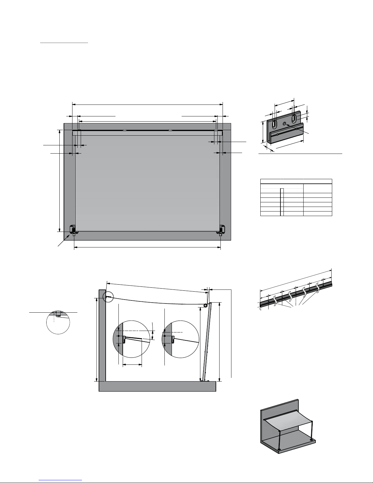
MEASUREMENTS FOR SHADEONE® WITH COLUMNS
INFORMATION VALID FOR INOX AND BASIC DESIGNS
Measurements for
Wall Consoles
Zeichnungsname
17 .01.2 01 5
Da tum
Maßstab
Format
Für diese Zeichnung behalten wir uns alle Rechte vor!
A4
Speichername:
Varianten Spannelemente shadeon e 02.dwg
shaDEsign GmbH. & Co KG
Technologiepark Villac h
Europastraße 8, 952 4 St. Magdalen, AUSTRIA
Montage INOX-Säule 60x60
mit Bodenplatte
1:35
Distance from furthest point of extension to point of
tensioning cable deflection on tensioning element: 0 - 100cm
End of sail attachment rail to
beginning of console: 10 cm
End of sail attachment rail to
beginning of console: 10 cm
Mount consoles at equal distances
Extension length INOX: 150 - 575 cm
Extension length BASIC: 150 - 400 cm
Minimum height for installation of consoles =
height of tensioning cable deflection on tensioning element
INOX: 185 - 300 cm
BASIC: 240 cm
Width of
consoles:
10 cm
Width of
consoles:
10 cm
Variation with protective roof
Variation without protective roof
Headroom height
at least 200 cm
Minimum of
4.5 cm free
above
Minimum of
4.5 cm free above
5
°
Approx.
18 cm
9 cm
9 cm
Distance between tensioning cables approx. 3cm less than width of system
Extension length: 150 - 575 cm
60 mm
100 mm
10 mm
Installation screws
for movement area
M10
thread
6,5 mm
13 mm
59 mm
18 mm
Shade System width INOX: 200 - 600 cm
BASIC: 200 - 400 cm
Shade System width
6,2 cm
6,2 cm
Example of Installation:
(For more examples of installation,
see page 12 onwards)
3 4 5 6
Zeichnungsname
17.01.2015
Datum
Maßstab
Format
Für diese Zeichnung behalten wir uns alle Rechte vor!
A4
Speichername:
Varianten Spannelemente shadeone 02.dwg
shaDEsign GmbH. & Co KG
Technologiepark Villach
Europastraße 8, 9524 St. Magdalen, AUS TRIA
Montage INOX-Säule ø60
mit Bodenplatte
1:35
Abstand Kederprofilende zu
Konsolenanfang: 15 cm
Mindest-Montagehöhe Konsolen =
Höhe Seilumlenkung am Spannelement
A
u
s
f
a
lls
lä
n
g
e
:
1
5
0
-
5
7
5
c
m
Distanz Ausfalllänge zu Spannseilumlenkung
am Spannelement: 0 - 100 cm
240 cm (Standard)
Wichtiger Hinweis:
Bei Distanz Ausfalllänge zu Spannseilumlenkung größer
100cm , zwecks Durchgangshöhe und System beweglichkeit
bitte jedenfalls mit dem Hersteller Rücksprache halten.
Konsolen-
breite:
10 cm
Variante mit Schutzdach
Variante ohne Schutzdach
6,2 cm
min. 3 cm
nach oben frei
5
°
6,2 cm
min. 4,5 cm
nach oben frei
c
a
.
1
8
c
m
View from Above:
Side View:
Important Information
– A winter protection bag cannot be used for the variation with protective roof
– In cases where the distance between furthest extension point and point of
tensioning cable deection on tensioning element is greater than 100cm, please
contact the manufacturer in order to discuss the headroom height, system
moveability and the increased wear and tear on tensioning cable.
Twister-Sail:
– At gradients of 0 % to 40 % (0° to 22°)
– Water drains o automatically from a gradient of 14 % (8°)
Zeichnungsname
17 .01.2 01 5
Da tum
Maßstab
Format
A4
Montage INOX-Säule 60x60
mit Bodenplatte
1:35
Distance from furthest point of extension to point of
tensioning cable deflection on tensioning element: 0 - 100cm
Minimum height for installation of consoles =
height of tensioning cable deflection on tensioning element
INOX: 185 - 300 cm
BASIC: 240 cm
Variation with protective roof
Variation without protective roof
Headroom height
at least 200 cm
Minimum of
4.5 cm free
above
Minimum of
4.5 cm free above
5
°
Approx.
18 cm
Extension length: 150 - 575 cm
6,2 cm
6,2 cm
Distance from furthest point of extension to point of
End of sail attachment rail to
beginning of console: 10 cm
End of sail attachment rail to
beginning of console: 10 cm
Mount consoles at equal distances
Extension length INOX: 150 - 575 cm
Extension length BASIC: 150 - 400 cm
Minimum height for installation of consoles =
height of tensioning cable deflection on tensioning element
INOX: 185 - 300 cm
BASIC: 240 cm
Width of
consoles:
10 cm
Width of
consoles:
10 cm
Variation with protective roof
Variation without protective roof
Headroom height
at least 200 cm
Minimum of
4.5 cm free
above
Minimum of
4.5 cm free above
5
°
Approx.
18 cm
9 cm
9 cm
Distance between tensioning cables approx. 3cm less than width of system
Extension length: 150 - 575 cm
Shade System width INOX: 200 - 600 cm
BASIC: 200 - 400 cm
Shade System width
6,2 cm
6,2 cm
For INOX,
optional oor
plates
Number of Wall Consoles:
Kederschiene
mit Schutzdach
von - bis
200 cm - 240 cm 3 Stk.
241 cm - 340 cm 4 Stk.
341 cm - 440 cm 5 Stk.
441 cm - 540 cm 6 Stk.
541 cm - 600 cm 7 Stk.
Anzahl der s tandardmäßi g mitgeliefert en Konsolen
Anlagenbrei te
Anzahl Ko nsolen
A
Zeichnungsname
05.02.2015
Datum
Maßstab
Format
Für diese Zeichnung behalten wir uns all e Rechte vor!
A4
Abmessungen shadeone.dwg
shaDEsign GmbH. & Co KG
Technologiepark Villach
Europastraße 8, 9524 St. Magdalen, AUSTRIA
Abmessungen SHADEONE
1:40
3 4 5 6
150150
62
Montagehöhe Konsolen
shadeone Spannsäule
Rund ø60 Inox
45min.
6
°
c
a
.
1
9
0
Seitenansicht
Abmessungen
Konsole
A
u
s
f
a
ll
3
1
7
200 cm
Number of consoles delivered as standard
Width of system
From To
Number of
Consoles
230 cm 3.
4.
5.
6.
7.
231 cm 330 cm
331 cm 430 cm
431 cm 530 cm
531 cm 600 cm
Alternative to Wall Consoles:
Pleas note:
(a) The outer-most installation holes at
either end should be no closer than
20 cm to the edge of the system
(b) The internal distances between
the installation holes should be
no greater than 100 cm
Console Rail
(N.B.: Not compatible with winter
protection bag!)
(a)
(a)
(b)
(b)
(b)
(b)
Length of console rail = length of system minus 3 cm
59 mm
18 mm
Installation holes are
drilled into the console rail
during installation
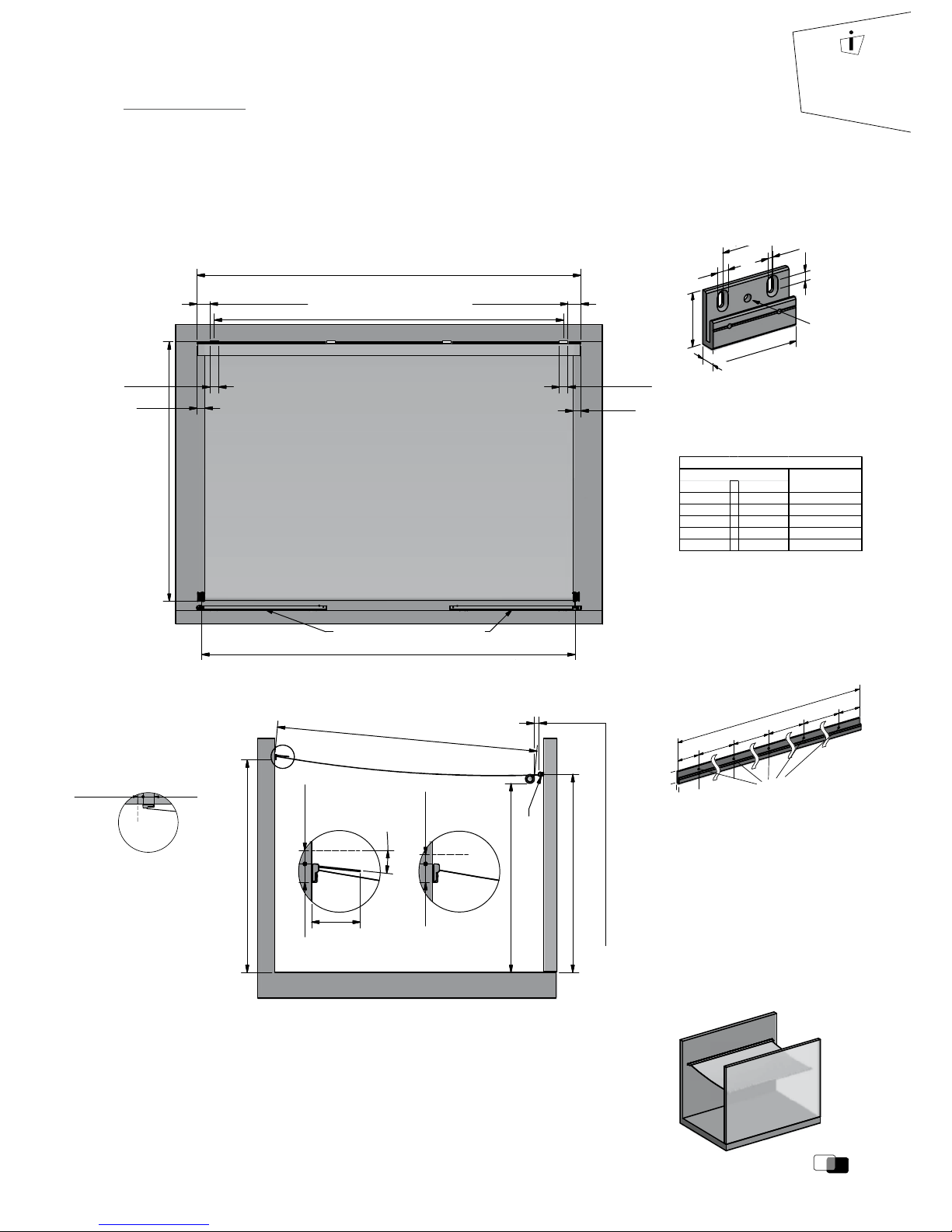
Alternative: Installation on ceiling
(Can only be implemented
without protective roof)
6,2 cm
min. 4,5 cm away
from the back
Page 3
3
shadesign.
Side View:
Zeichnungsname
17 .01.2 01 5
Da tum
Maßstab
Format
Für diese Zeichnung behalten wir uns alle Rechte vor!
A4
Speichername:
Varianten Spannelemente shadeon e 02.dwg
shaDEsign GmbH. & Co KG
Technologiepark Villac h
Europastraße 8, 952 4 St. Magdalen, AUSTRIA
Montage Wandhalter
waagrecht quer montiert
1:35
Shade system width 200 - 600 cm.
System width for horizontal tensioning element from 300 cm
Extension length 150 - 575 cm
Heigth at which tensioning element is installed
Tensioning element
installed horizontally
Distance between tensioning cables approx. 3 cm less than width of system
5
°
9 cm
9 cm
End of sail attachment rail to
beginning of console: 10 cm
End of sail attachment rail to
beginning of console: 10 cm
60 mm
100 mm
10 mm
Installation screws
for movement area
M10
thread
6,5 mm
13 mm
59 mm
18 mm
Mount consoles at equal distances
Width of
consoles:
10 cm
Width of
consoles:
10 cm
Tensioning element installed horizontally
Distance from furthest point of extension to point of
tensioning cable deflection on tensioning element: 0 - 100cm
Minimum height for installation of consoles =
height of tensioning cable deflection on tensioning element
Headroom height
at least 200 cm
Extension length: 150 - 575 cm
Variation with protective roof
Minimum of
4.5 cm free
above
Approx.
18 cm
6,2 cm
Variation without protective roof
Minimum of
4.5 cm free above
6,2 cm
MEASUREMENTS FOR SHADEONE® STRUCTURE
Important Information
– A winter protection bag cannot be used for the variation with protective roof
– In cases where the distance between furthest extension point and point of
tensioning cable deection on tensioning element is greater than 100cm, please
contact the manufacturer in order to discuss the headroom height, system
moveability and the increased wear and tear on tensioning cable.
Twister-Sail:
– At gradients of 0 % to 40 % (0° to 22°)
– Water drains o automatically from a gradient of 14 % (8°)
Number of Wall Consoles:
Alternative to Wall Consoles:
Pleas note:
(a) The outer-most installation holes at
either end should be no closer than
20 cm to the edge of the system
(b) The internal distances between
the installation holes should be
no greater than 100 cm
Console Rail
(N.B.: Not compatible with winter
protection bag!)
(a)
(a)
(b)
(b)
(b)
(b)
Length of console rail = length of system minus 3 cm
59 mm
18 mm
Installation holes are
drilled into the console rail
during installation
Shade system width 200 - 600 cm.
System width for horizontal tensioning element from 300 cm
Extension length 150 - 575 cm
Heigth at which tensioning element is installed
Tensioning element
installed horizontally
Distance between tensioning cables approx. 3 cm less than width of system
5
°
9 cm
9 cm
End of sail attachment rail to
beginning of console: 10 cm
End of sail attachment rail to
beginning of console: 10 cm
Mount consoles at equal distances
Width of
consoles:
10 cm
Width of
consoles:
10 cm
Tensioning element installed horizontally
Distance from furthest point of extension to point of
Minimum height for installation of consoles =
height of tensioning cable deflection on tensioning element
Headroom height
at least 200 cm
Extension length: 150 - 575 cm
Variation with protective roof
Minimum of
4.5 cm free
above
Approx.
18 cm
6,2 cm
Variation without protective roof
Minimum of
4.5 cm free above
6,2 cm
Zeichnungsname
17 .01.2 01 5
Da tum
Maßstab
Format
A4
Montage Wandhalter
waagrecht quer montiert
1:35
Heigth at which tensioning element is installed
Tensioning element
installed horizontally
5
°
Distance from furthest point of extension to point of
tensioning cable deflection on tensioning element: 0 - 100cm
Minimum height for installation of consoles =
height of tensioning cable deflection on tensioning element
Headroom height
at least 200 cm
Extension length: 150 - 575 cm
Variation with protective roof
Minimum of
4.5 cm free
above
Approx.
18 cm
6,2 cm
Variation without protective roof
Minimum of
4.5 cm free above
6,2 cm
3 4 5 6
Zeichnungsname
17.01.2015
Datum
Maßstab
Format
Für diese Zeichnung behalten wir uns alle Rechte vor!
A4
Speichername:
Varianten Spannelemente shadeone 02.dwg
shaDEsign GmbH. & Co KG
Technologiepark Villach
Europastraße 8, 9524 St. Magdalen, AUS TRIA
Montage Wandhalter
waagrecht quer montiert
1:35
Abstand Kederprofilende zu
Konsolenanfang: 15 cm
A
u
s
f
a
lls
lä
n
g
e
:
1
5
0
-
5
7
5
c
m
Distanz Ausfalllänge zu Spannseilumlenkung
am Spannelement: 0 - 100 cm
Montagehöhe Wandhalter
Wandhalter
quer montiert
Mindest-Montagehöhe Konsolen =
Höhe Seilumlenkung am Spannelement
Wichtiger Hinweis:
Bei Distanz Ausfalllänge zu Spannseilumlenkung größer
100cm , zwecks Durchgangshöhe und Systembeweglichkeit
bitte jedenfalls mit dem Hersteller Rücksprache halten.
Variante mit Schutzdach
Variante ohne Schutzdach
6
°
6,2 cm
min. 4,5 cm
frei nach oben
c
a
.
1
9
c
m
6,2 cm
min. 3 cm
nach oben frei
Konsolen-
breite:
10 cm
All measurements
given in millimetres
unless otherwise
stated
Measurements for
Wall ConsolesView from Above:
Kederschiene
mit Schutzdach
von - bis
200 cm - 240 cm 3 Stk.
241 cm - 340 cm 4 Stk.
341 cm - 440 cm 5 Stk.
441 cm - 540 cm 6 Stk.
541 cm - 600 cm 7 Stk.
Anzahl der s tandardmäßi g mitgeliefert en Konsolen
Anlagenbrei te
Anzahl Ko nsolen
A
Zeichnungsname
05.02.2015
Datum
Maßstab
Format
Für diese Zeichnung behalten wir uns all e Rechte vor!
A4
Abmessungen shadeone.dwg
shaDEsign GmbH. & Co KG
Technologiepark Villach
Europastraße 8, 9524 St. Magdalen, AUSTRIA
Abmessungen SHADEONE
1:40
3 4 5 6
150150
62
Montagehöhe Konsolen
shadeone Spannsäule
Rund ø60 Inox
45min.
6
°
c
a
.
1
9
0
Seitenansicht
Abmessungen
Konsole
A
u
s
f
a
ll
3
1
7
200 cm
Number of consoles delivered as standard
Width of system
From To
Number of
Consoles
230 cm 3.
4.
5.
6.
7.
231 cm 330 cm
331 cm 430 cm
431 cm 530 cm
531 cm 600 cm
Example of Installation:
(For more examples of installation,
see page 12 onwards)
Alternative: Installation on ceiling
(Can only be implemented
without protective roof)
6,2 cm
min. 4,5 cm away
from the back
Page 4
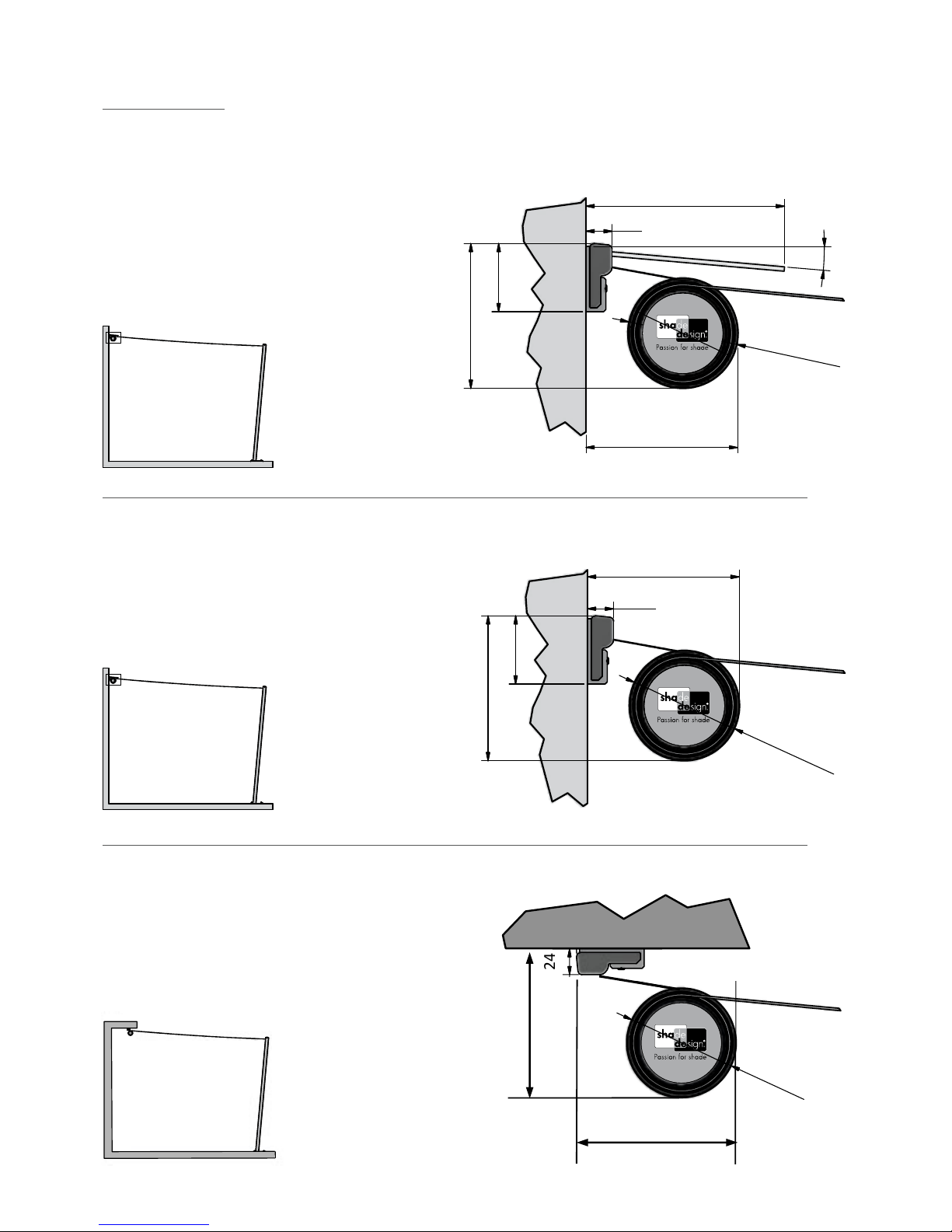
MEASUREMENTS FOR SHADEONE® WHEN ROLLED UP
Detailansicht A
mit Schutzdach
Detailansicht A
ohne Schutzdach
3 4 5 6
Zeichnungsname
16.01.2015
Datum
Maßstab
Format
Für diese Zeichnung behalten wir uns a lle Rechte vor!
A4
shaDEsign GmbH. & Co KG
Technologiepark Villach
Europastraße 8, 9524 St. Magdalen, AUSTRIA
Abmessungen SHADEONE
Segel eingerollt - Seitenansicht
1:50/1:3
A
6
2
190
24
c
a
.
Ø
1
1
0
ca. 135
c
a.
Ø
1
1
0
6
2
1
3
1
c
a
.
6°
24
Detailansicht A
mit Schutzdach
Detailansicht A
ohne Schutzdach
3 4 5 6
Zeichnungsname
16.01.2015
Datum
Maßstab
Format
Für diese Zeichnung behalten wir uns a lle Rechte vor!
A4
shaDEsign GmbH. & Co KG
Technologiepark Villach
Europastraße 8, 9524 St. Magdalen, AUSTRIA
Abmessungen SHADEONE
Segel eingerollt - Seitenansicht
1:50/1:3
A
6
2
190
24
c
a
.
Ø
1
1
0
ca. 135
c
a.
Ø
1
1
0
6
2
1
3
1
c
a
.
6°
24
Detailed perspective A: wall
Installation with protective roof
N.B.: A winter protection bag cannot be used
for the variation with protective roof
Detailed perspective A: wall
installation without protective roof
Detailed perspective B: installation
on ceiling without protective roof
Detailansicht A
mit Schutzdach
Detailansicht A
ohne Schutzdach
3 4 5 6
Zeichnungsname
16.01.2015
Datum
Maßstab
Format
Für diese Zeichnung behalten wir uns a lle Rechte vor!
A4
shaDEsign GmbH. & Co KG
Technologiepark Villach
Europastraße 8, 9524 St. Magdalen, AUSTRIA
Abmessungen SHADEONE
Segel eingerollt - Seitenansicht
1:50/1:3
A
6
2
190
24
c
a
.
Ø
1
1
0
ca. 135
c
a.
Ø
1
1
0
6
2
1
3
1
c
a
.
6°
24
Detailansicht A
ohne Schutzdach
Zeichnungsname
Eingerollt
ca. 150
c
a
.
Ø
1
1
0
62
ca. 130
24
Zeichnungsname
Abmessungen SHADEONE
Segel eingerollt - Seitenansicht
ca. 135
c
a.
Ø
1
1
0
24
Detailansicht A
ohne Schutzdach
Zeichnungsname
Datum
Maßstab
Format
shaDEsign GmbH. & Co KG
Technologiepark Villach
Abmessungen SHADEONE
Segel eingerollt - Seitenansicht
ca. 135
c
a.
Ø
1
1
0
6
2
1
3
1
c
a
.
24
B
Detailansicht A
ohne Schutzdach
3 4 5 6
Zeichnungsname
16.01.2015
Datum
Maßstab
Format
Für diese Zeichnung behalten wir uns alle Rechte vor!
A4
Speichername:
Abmessungen shadeone.dwg
shaDEsign GmbH. & Co KG
Technologiepark Villach
Europastraße 8, 9524 St. Magdalen, AUSTRIA
Abmessungen SHADEONE
Segel eingerollt - Seitenansicht
1:50/1:3
190
c
a
.
Ø
1
1
0
ca. 135
c
a.
Ø
1
1
0
6
2
1
3
1
c
a
.
24
Zeichnungsname
05.02.2015
Datum
Maßstab
Format
A4
Abmessungen SHADEONE
Segel eingerollt - Seitenansicht
1:50/1:3
Eingerollt
ca. 150
c
a
.
Ø
1
1
0
24
16.01.2015
Datum
Format
A4
c
a.
Ø
1
1
0
Zeichnungsname
16.01.2015
Datum
Maßstab
Format
A4
Abmessungen SHADEONE
Segel eingerollt - Seitenansicht
1:50/1:3
ca. 135
c
a.
Ø
1
1
0
24
Datenblattheft2017Ergänzung1:Seite4–EinfügenDeckenmontageBild+Bemaßung
Detailansicht A
mit Schutzdach
Detailansicht A
ohne Schutzdach
3 4 5 6
Zeichnungsname
Maßstab
Für diese Zeichnung behalten wir uns alle Rechte vor!
shaDEsign GmbH. & Co KG
Technologiepark Villach
Europastraße 8, 9524 St. Magdalen, AUSTRIA
Abmessungen SHADEONE
Segel eingerollt - Seitenansicht
1:50/1:3
A
6
2
190
24
c
a
.
Ø
1
1
0
ca. 135
6
2
1
3
1
c
a
.
6°
24
Detailansicht A
mit Schutzdach
Detailansicht A
ohne Schutzdach
A
Zeichnungsname
180
Eingerollt
ca. 150
62
Eingerollt
ca. 130
24
Detailansicht A
ohne Schutzdach
3 4 5 6
Zeichnungsname
Abmessungen SHADEONE
Segel eingerollt - Seitenansicht
190
24
c
a
.
Ø
1
1
0
ca. 135
c
a.
Ø
1
1
0
6
2
1
3
1
c
a
.
6°
24
Detailansicht A
mit Schutzdach
Detailansicht A
ohne Schutzdach
1 2
3 4 5 6
Zeichnungsname
Maßstab
shaDEsign GmbH. & Co KG
Technologiepark Villach
Abmessungen SHADEONE
Segel eingerollt - Seitenansicht
A
6
2
190
c
a
.
1
3
0
24
c
a
.
Ø
1
1
0
ca. 135
6
2
1
3
1
c
a
.
6°
24
Detailansicht A
ohne Schutzdach
Eingerollt
ca. 150
Detailansicht A
ohne Schutzdach
Eingerollt
ca. 150
24
B
24
Eingerollt
c
a.130
D
D
D
Speichername:
Europastraße 8, 9524 St. Magdalen, AUSTRI A
D
A
D
C
B
Für diese Zeichnung behalten wir uns alle Rechte vor!
Speichername:
Abmessungen shadeone.dwg
shaDEsign GmbH. & Co KG
Technologiepark Vil lach
Europastraße 8, 9524 St. Magdalen, AUSTR IA
62
Eingerollt
ca. 130
24
c
a
.
Ø
1
1
0
62
Eingerollt
ca. 130
5
°
Eingerollt
ca. 150
ca. 130
Detailansicht A
mit Schutzdach
Detailansicht A
ohne Schutzdach
A
D
C
B
A
Zeichnungsname
05.02.2015
Datum
Maßstab
Format
Für diese Zeichnung behalten wir uns alle Rechte vor!
A4
Speichername:
Abmessungen shadeone.dwg
shaDEsign GmbH. & Co KG
Technologiepark Villach
Europastraße 8, 9524 St. Magdalen, AUSTRIA
Abmessungen SHADEONE
Segel eingerollt - Seitenansicht
1:50/1:3
62
180
Eingerollt
ca. 130
24
c
a
.
Ø
1
1
0
Eingerollt
ca. 150
c
a
.
Ø
1
1
0
62
Eingerollt
ca. 130
24
5
°
Eingerollt
ca. 150
mit Schutzdach
ohne Schutzdach
A
D
C
B
A
Zeichnungsname
Maßstab
Für diese Zeichnung behalten wir uns alle Rechte vor!
Speichername:
Abmessungen shadeone.dwg
shaDEsign GmbH. & Co KG
Technologiepark Villach
Europastraße 8, 9524 St. Magdalen, AUSTRIA
Abmessungen SHADEONE
Segel eingerollt - Seitenansicht
1:50/1:3
62
180
Eingerollt
ca. 130
24
c
a
.
Ø
1
1
0
Eingerollt
ca. 150
62
Eingerollt
ca. 130
24
5
°
Eingerollt
ca. 150
Detailansicht A
mit Schutzdach
Detailansicht A
ohne Schutzdach
D
C
B
A
1 2
3 4 5 6
Für diese Zeichnung behalten wir uns alle Rechte vor!
Speichername:
Abmessungen shadeone.dwg
shaDEsign GmbH. & Co KG
Technologiepark Villach
Europastraße 8, 9524 St. Magdalen , AUSTRIA
A
6
2
190
c
a
.
1
3
0
24
c
a
.
Ø
1
1
0
6
2
1
3
1
c
a
.
6°
Detailansicht A
mit Schutzdach
Detailansicht A
ohne Schutzdach
A
1 2 3 4 5 6
Zeichnungsname
05.02.2015
Datum
Maßstab
Format
Für diese Zeichnung behalten wir uns alle Rechte vor!
A4
Speichername:
Abmessungen shadeone.dwg
shaDEsign GmbH. & Co KG
Technologiepark Vil lach
Europastraße 8, 9524 St. Magdalen, AUSTR IA
Abmessungen SHADEONE
Segel eingerollt - Seitenansicht
1:50/1:3
180
24
c
a
.
Ø
1
1
0
Eingerollt
ca. 150
c
a
.
Ø
1
1
0
62
Eingerollt
ca. 130
24
5
°
Eingerollt
ca. 150
Detailansicht A
mit Schutzdach
Detailansicht A
ohne Schutzdach
3 4 5 6
Zeichnungsname
16.01.2015
Datum
Maßstab
Format
Für diese Zeichnung behalten wir uns alle Rechte vor!
A4
Speichername:
Abmessungen shadeone.dwg
shaDEsign GmbH. & Co KG
Technologiepark Villach
Europastraße 8, 9524 St. Magdalen, AUSTRI A
Abmessungen SHADEONE
Segel eingerollt - Seitenansicht
1:50/1:3
A
6
2
190
24
c
a
.
Ø
1
1
0
ca. 135
c
a.
Ø
1
1
0
6
2
1
3
1
c
a
.
6°
24
Detailansicht A
mit Schutzdach
Detailansicht A
ohne Schutzdach
D
C
B
A
1 2
3 4 5 6
Zeichnungsname
16.01.2015
Datum
Maßstab
Format
Für diese Zeichnung behalten wir uns alle Rechte vor!
A4
Speichername:
Abmessungen shadeone.dwg
shaDEsign GmbH. & Co KG
Technologiepark Villach
Europastraße 8, 9524 St. Magdalen, AUSTRI A
Abmessungen SHADEONE
Segel eingerollt - Seitenansicht
1:50/1:3
A
6
2
190
c
a
.
1
3
0
24
c
a
.
Ø
1
1
0
ca. 135
c
a.
Ø
1
1
0
6
2
1
3
1
c
a
.
6°
24
Eingerollt
ca. 150
c
a
.
Ø
1
1
0
24
Detailansicht A
ohne Schutzdach
Eingerollt
ca. 150
c
a
.
Ø
1
1
0
62
24
Detailansicht A
ohne Schutzdach
c
a
.
Ø
1
1
0
Eingerollt
ca. 150
c
a
.
Ø
1
1
0
62
Eingerollt
ca. 130
24
5
°
Eingerollt
ca.150
Detailansicht A
mit Schutzdach
Detailansicht A
ohne Schutzdach
62
180
24
Ø
1
1
0
Approx.
Ø
1
1
0
Approx.
62
24
5
°
Rolled up
Approx. 150
Rolled up
Approx. 150
Rolled up
Approx. 130
Rolled up
Approx. 130
Detailansicht A
ohne Schutzdach
Ø
1
1
0
Approx.
62
24
Rolled up
Approx. 150
Rolled up
Approx. 130
Rolled up
Approx. 150
Approx.
ø
110
Rolled up
Approx. 130
Page 5
5
shadesign.
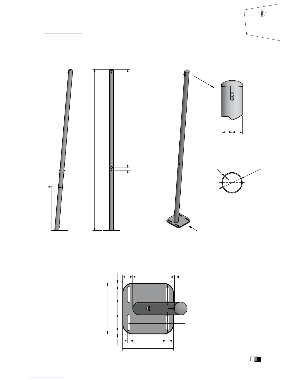
Optional oor plate
(attached and screwed on)
Outlet for
tensioning cable
MEASUREMENTS FOR SHADEONE® INOX
WITH ROUND STAINLESS STEEL COLUMNS
5
°
1850 - 3000 mm
Spannsäule SHADEONE INOX
Rund ø 60,3 mm
Hole for tensioning crank: 1440 mm
Fixing screw: 40
Zeichnungsname
05.02.2015
Datum
Maßstab
Format
Für diese Zeichnung behalten wir uns alle Rechte vor!
A3
Speichername:
Abmessungen shadeone.dwg
shaDEsign GmbH . & Co KG
Technologiepark Villach
Europastraße 8, 9524 St. Magdalen, AUST RIA
shadeone Steher Inox
Abmessungen / Grundplatte
1:15
5
°
1850 - 3000 mm
250 mm
250 mm
50
250
63
74
63
250
190
14 14
10
8
5
°
Stehrfuß shadeone M 1:5
Spannsäule SHADEONE INOX
Rund ø 60,3 mm
Dependent on
length of columns
(160 - 260 mm)
190 30
14 14
25
63
74
63
25
Hole for tensioning crank: 1440 mm
Fixing screw: 40
1850 - 3000 mm
Hole for tensioning crank: 1440 mm
Fixing screw: 40
A ( 1 : 3 )
30,15 30,15
A ( 1 : 3 )
30,15 30,15
Ø
6
0
,
3
2
Outlet for
tensioning cable:
Prole section:
All measurements
given in millimetres
unless otherwise
stated
Page 6

5
°
1850 - 3000 mm
50
5
°
1850 - 3000 mm
50
250
63
74
63
250
190
14 14
10
8
5
°
Stehrfuß shadeone M 1:5
Spannsäule SHADEONE INOX
Rund ø 60,3 mm
Dependent on
length of columns
(160 - 260 mm)
Dependent on
length of columns
(160 - 260 mm)
25
25
Hole for tensioning crank: 1440 mm
Fixing screw: 40
MEASUREMENTS FOR SHADEONE® INOX
WITH SQUARE STAINLESS STEEL COLUMNS
5
°
1850 - 3000 mm
5
°
1850 - 3000 mm
250
63
74
63
250
190
14 14
10
8
5
°
Stehrfuß shadeone M 1:5
Spannsäule SHADEONE INOX
Rund ø 60,3 mm
Hole for tensioning crank: 1440 mm
Fixing screw: 40
5
°
1850 - 3000 mm
1850 - 3000 mm
250
63
74
63
250
190
14 14
10
8
5
°
Stehrfuß shadeone M 1:5
Spannsäule SHADEONE INOX
Rund ø 60,3 mm
Hole for tensioning crank: 1440 mm
Fixing screw: 40
Hole for tensioning crank: 1440 mm
Fixing screw: 40
Zeichnungsname
Für diese Zeichnung behalten wir uns alle Rechte vor!
Speichername:
Abmessungen shadeone.dwg
shaDEsign GmbH . & Co KG
Technologiepark Villach
Europastraße 8, 9524 St. Magdalen, AUST RIA
shadeone Steher Inox
Abmessungen / Grundplatte
5
°
250 mm
250 mm
50
5
°
1850 - 3000 mm
250 mm
250 mm
50
250
63
74
63
250
190
14 14
10
8
5
°
Stehrfuß shadeone M 1:5
Spannsäule SHADEONE INOX
Rund ø 60,3 mm
Dependent on
length of columns
(160 - 260 mm)
Dependent on
length of columns
(160 - 260 mm)
25
63
74
63
25
R
5
0
190 30
14 14
190 30
14 14
25
63
74
63
25
Hole for tensioning crank: 1440 mm
Fixing screw: 40
A ( 1 : 3 )
30 30
A ( 1 : 3 )
30 30
60
60
2
Optional oor plate
(attached and screwed on)
Outlet for
tensioning cable
Outlet for
tensioning cable:
Prole section:
Page 7

7
shadesign.
A ( 1 : 5 )
4030 30
100
100
60
2
MEASUREMENTS FOR SHADEONE® INOX
WITH SQUARE STAINLESS STEEL COLUMNS DOUBLE DESIGN
MEASUREMENTS FOR SHADEONE® INOX STAINLESS STEEL ELBOWED
SINGLE ROUND OR SQUARE / DOUBLE SQUARE
Optional
oor plate
(welded on)
(5)
Optional oor plate
(screwed or welded on,
depending on design!)
A ( 1 : 5 )
5
°
1850 - 3000 mm
4030 30
50 160-260
100
100
60
2
Fixing screw: 40
Hole for tensioning crank:
1440 mm
A ( 1 : 5 )
1850 - 3000 mm
4030 30
100
100
60
2
Fixing screw: 40
Hole for tensioning crank:
1440 mm
A ( 1 : 5 )
4030 30
25
63
164
63
25
340
138,5
63
138,5
30 190 30
250
50
160 - 260 mm
100
100
60
2
Dependent on
length of columns
A ( 1 : 5 )
4030 30
100
A ( 1 : 5 )
4030 30
100
100
60
2
Floor plate:
SUMMARY OF IMPORTANT INFORMATION:
(1) Max. overall tube length of the elbowed jack column: 300 cm
(2) Elbowed length must be no less than 150 cm from the top to the bend
(3) The angle of the elbow bend must be between 0° and 45°
(4) Measurement of extension: distance from front edge of cylinder to top of jack column: at least 15 cm!
(5) Optional oor plates:
• Single column (round or square): if the angle between oor plate and jack column axis is 85°, the oor
plate is screwed on; otherwise it is welded on
• Square double column: oor plate is always welded on
(3)
Angle of
elbow
max. 45°
(4) Measurement of extension:
min. distance from front edge of
cylinder to top of jack
column: 15cm!
min. 150
(2) Min. 150 cm
(NOTE: measured from
the bend)
(1) Max. length
= 300 cm
minus length of
elbowed (note:
measured from the
bend)
Optional oor plates:
Angle selectable
All measurements
given in millimetres
unless otherwise
stated
Outlet for
tensioning
cable
Outlet for tensioning cable:Prole section:
Page 8

#$%
#
MEASUREMENTS FOR SHADEONE® INOX STAINLESS STEEL COLUMN
75 CM HEIGHT ADJUSTABLE ROUND / SQUARE
5
°
2
(1)
420 - 3000
860 (Slit)
Hole for tensioning crank: 1410
55
Cable adjustment
area 750
35
5
°
80
80
80
5
°
2
(1)
420 - 3000
860 (Slit)
Hole for tensioning crank: 1410
55
Cable adjustment
area 750
35
5
°
80
80
80
5
°
25
63
74
63
25
250
30 190 30
250
50
Dependent on
length of column
210 - 260
Front edge of
top of column
Dependent on
length of column
210 - 260
Front edge of
top of column
2
(1)
420 - 3000
860 (Slit)
Hole for tensioning crank: 1410
55
Cable adjustment
area 750
35
5
°
25
63
74
63
25
250
30 190 30
250
50
80
80
80
Dependent on
length of column
210 - 260
Front edge of
top of column
5
°
25
63
74
63
25
250
30 190 30
250
50
5
°
Optional oor plate
(attached and screwed on)
2
(1)
420 - 3000
860 (Slit)
Hole for tensioning crank: 1410
55
Cable adjustment
area 750
35
5
°
min. 300
(4) PLEASE NOTE:
Positioning of stainless steel column: minimum distance
from front edge of completely extended sail to tip of
stainless steel column: min. 30cm!
(3) PLEASE NOTE:
Crank rotation axis: a radius of 25cm around the crank
rotation axis is needed in order to adjust the height.
No objects should be placed in its way.
(2) Height of crank rotation axis:
100cm to <length of column
minus 85cm>!
SUMMARY OF IMPORTANT INFORMATION:
(1) Total length of jack column: min. 242 cm, max. 300 cm
(2) Height of crank rotation axis: 100cm to <length of
column minus 85cm>! (Example: with a jack column
length of 300cm, the crank rotation axis would be at a
height of 100 to 215cm.
(3) Crank rotation axis: a radius of 25cm around the crank
rotation axis is needed in order to adjust the height. No
objects should be placed in its way (determine height
of crank rotation axis accordingly!).
(4) Positioning of stainless steel column: minimum
distance from front edge of completely extended sail
to tip of stainless steel column: min. 30cm!
(5) Angle between direct line from the top of the stainless
steel column to point at which sail and stainless steel
axis are mounted onto wall must be between 85° and
100°! (Example: if stainless steel column is vertical, the
maximum gradient of the sail can be 15°)
Optional oor plate
(attached and screwed on)
(5) PLEASE NOTE:
Angle between direct
line from the top of the
stainless steel column
to point at which sail
and stainless steel axis
are mounted onto wall
must be between 85°
and 100°!
Page 9

9
shadesign.
MEASUREMENTS FOR SHADEONE® BASIC STEEL COLUMN
MEASUREMENTS FOR SHADEONE® STRUCTURE TENSIONING ELEMENT
View of Installation Bracket:
324
5
°
2390
380
5
°
2399
Hole for tensioning crank: 2115
95 95
Ø
3
4
0
380
5
°
2399
Spannsäule BASIC
Rund Ø 60,3mm
Zeichnungsname
Maßstab
Für diese Zeichnung behalten wir uns alle Rechte vor!
Speichername:
Abmessungen shadeone.dwg
shaDEsign GmbH. & Co KG
Technologiepark Villach
Europastraße 8, 9524 St. Magdalen, AUSTRIA
SHADEONE BASIC
Abmessungen / Grundplatten
1:15
63
74
63
95 95
14 14
Ø
3
4
0
324
5
°
2390
Ø
3
4
0
380
5
°
2399
Spannsäule BASIC
Vierkant 40x40
Stahl, verzinkt + gepulvert
Spannsäule BASIC
Rund Ø 60,3mm
Stahl, verzinkt + gepulvert
Hole for tensioning crank: 2115
75 208
25
63
74
63
25
250
14 14
190 30
250
Zeichnungsname
16.01.2015
Datum
Maßstab
Format
Für diese Zeichnung behalten wir uns alle Rechte vor!
A4
shaDEsign GmbH. & Co KG
Technologiepark Villach
Europastraße 8, 9524 St. Magdalen, AUSTRIA
Wandhalter shadeone
Ausführung Lang / Abmessungen
1:6
1 2
3 4 5 6
1485
4
0
15
1
5
Mittelposition
Montageschraube
±20 mm
Bewegung möglich
2020
5
3
,
5
±8 mm Bewegung möglich
n
2
1
36
88
Ansicht Montagelasche M 1:2
waagrechte Montage
senkrechte Montage
Montage Wandhalter kurz mit:
- 2 Schrauben M10, 6-Kant-Kopf
- 2 Beilagscheiben für M10
166
20
20
Bewegung möglich
4
0
1571162
20 20
Suggested screw:
M10 hexagonal screw + Washer
Central Position
Installation screw
± 20 mm
movement enabled
± 8 mm movement enabled
Horizontal Installation Vertical Installation
20 20
Prole section:
A ( 1 : 3 )
30 30
60
60
2
40
40
All measurements
given in millimetres
unless otherwise
stated
Outlet for tensioning cable:
Outlet for
tensioning cable
1 2
3 4 5 6
1485
4
0
15
1
5
166
20
20
Bewegung möglich
4
0
1571162
20 20
Movement enabled
Page 10

INSTALLATION ACCCESSORIES FOR SHADEONE® INOX
DESIGNER PIPE CLIP FIXED DISTANCE OF 25 MM, A2
Important Information:
- Installation components should only carry weight in a front-facing
direction (see diagram on the right)
- Minimum distance between two installation components on one
tensioning element: 60 cm
SINGLE COLUMN:
SINGLE COLUMN:
DOUBLE COLUMN:
DOUBLE COLUMN:
155
155
130
30
110
100
200
155
130
30
110
90 (M8)
90
30
70
155
100
200
155
130
30
110
100
200
155
130
30
110
88
25
88
105
90
50
60
10,5
25
90 (M8)
90
30
70
155
100
200
155
130
30
110
66
90
60,5
40
88
25
88
10,5
25
88
105
90
50
60
10,5
25
130
110
88
50
25
100
155
130
30
110
88
105
90
50
60
10,5
25
90 (M8)
90
30
70
155
100
200
155
130
30
110
66
90
60,5
40
88
25
88
10,5
25
88
105
90
50
60
10,5
25
Attachment surface
Installation
components
Tensioning element
Correct
direction of weigth
(front-facing)
Incorrect
direction of weigth
(side-facing)
COUNTER PLATES A2 + UBRACKETS A2
Page 11

11
shadesign.
Attachment surface
Installation
components
Tensioning element
Correct
direction of weigth
(front-facing)
Incorrect
direction of weigth
(side-facing)
40
4040
46
20 (M8)
INSTALLATION ACCCESSORIES FOR SHADEONE® BASIC + STRUCTURE
SPECIAL SOLUTIONS
COUNTER PLATES A2 + UBRACKETS A2 DESIGNER PIPE CLIP TWOPART A2
200
100
125
80 (M8)
50
70
30
40
4040
46
20 (M8)
PROFILE 40 X 40
CLAMPING
BRACKET
BASE PLATES
(FOR WALL
INSTALLATION)
SCREW FOUNDATION GALVANISED
ADAPTER FOR FLOOR PLATE GALVANISED
25 X 25 CM BASIC & INOX
200
100
125
80 (M8)
50
70
30
220
180
76
800
4 Stk.
M12
40
4040
46
20 (M8)
4
0
0
4
0
0
8
0
0
(
>
F
r
o
s
t
t
i
e
f
e
)
Bodenhülse
einbetoniert
570
Øinnen=105
dichter
Verschluss-
deckel
4 pc.
M12
All measurements
given in millimetres
unless otherwise
stated
Important Information:
- Installation components should only carry weight in a front-facing
direction (see diagram on the right)
- Minimum distance between two installation components on one
tensioning element: 60 cm
FULL HEAT PROTECTION MOUNTING PROFILE
ALUMINUM
Note: Any deviations of the
delivery length must
be stated separately in the
order! (Maximum length of
prole: 600 cm)
Profile section:
30
60
3
Profile section:
View:
30
60
3
Page 12

SHADEONE® VARIATIONS FOR INSTALLATION
INSTALLATION WITH 2 COLUMNS
BASIC OR INOX
INSTALLATION ONTO RAILINGS
WITH 2 COLUMNS
LEFT: 1X STRAIGHT INOX
RIGHT: 1X ELBOWED INOX
Page 13

13
shadesign.
SHADEONE® VARIATIONS FOR INSTALLATION
INSTALLATION WITH:
LEFT: 1 SINGLE COLUMN BASIC OR INOX
MIDDLE: 1 DOUBLE COLUMN INOX
RIGHT: 1 SINGLE COLUMN BASIC OR INOX
INSTALLATION WITH:
LEFT: 1 COLUMN BASIC OR INOX
RIGHT: 1 TENSIONING ELEMENT STRUCTURE VERTICAL
90° ROTATED PULLEY HEAD
Page 14

SHADEONE® VARIATIONS FOR INSTALLATION
INSTALLATION WITH:
LEFT: 1 TENSIONING ELEMENT STRUCTURE VERTICAL
RIGHT: 1 TENSIONING ELEMENT STRUCTURE
PARALLEL TO DIRECTION OF EXTENSION
90° ROTATED PULLEY HEAD
INSTALLATION WITH TWO TENSIONING
ELEMENTS STRUCTURE HORIZONTAL
Page 15

15
shadesign.
SHADEONE® VARIATIONS FOR INSTALLATION
INSTALLATION WITH:
LEFT: 1 COLUMN BASIC OR INOX
WITH SCREW FOUNDATION
RIGHT: 1 COLUMN INOX
WITH HEIGHT ADJUSTMENT
INSTALLATION WITH:
LEFT: 1 COLUMN BASIC OR INOX
WITH SCREW FOUNDATION
RIGHT: 1 COLUMN INOX
WITH CONCRETE FOUNDATION
width x length x depth = min. 40x40x80 cm]
Page 16

shadesign GmbH & Co KG
Technologiepark Villach | Europastraße 8 | 9524 St. Magdalen, Austria
Phone: +43 (0) 4242 44053-0 | Fax: +43 (0) 180 480535961 | office@shadesign.at | www.
shadesign.com
We do not assume liability for any misprints or errors.
zurück zur Produktübersicht
https://www.sonnensegel-pina.de/konfigurator/aufrollbare-sonnensegel-markise
 Loading...