

ShadeLab SVET Assembly Manual

Assembly manual

2 | | ASSEMBLY

INDEX
1 - INTRODUCTION ..............................................................page 4
1.1 - Symbols used in the manual ....................................................... page 4
1.2 - Personnel requirements .............................................................. page 4
1.3 - Equipment necessary ................................................................. page 5
1.4 - Before starting assembly ............................................................ page 5
2 - SAFETY .......................................................................page 6
2.1 - General safety information.......................................................... page 6
2.2 - Working environment ................................................................. page 6
3 - ASSEMBLY TECHNICAL TABLES ..........................................page 7
3.1 - Table of minimum dimensions for one pair of arms.................... page 7
3.2 - Motor power table ...................................................................... page 7
3.3 - Table of cutting dimensions ........................................................ page 8
3.4 - Table of compensator support brackets .....................................page 9
4 - SVET COMPONENTS AND DIAGRAMS ...................................page 10
4.1 - Tilting diagrams .......................................................................... page 10
4.2 - Awning components ................................................................... page 11
4.3 - Material necessary for assembly ................................................page 12
5 - AWNING ASSEMBLY ........................................................page 13
6 - REGULATING THE AWNING ................................................page 18
6.1 - Troubleshooting .......................................................................... page 19
7 - REMOVING AND PACKING THE AWNING ................................page 21
7.1 - Removing ....................................................................................page 21
7.2 - Packing ....................................................................................... page 21

1 - INTRODUCTION
This “assembly manual” for SVET awnings has been produced by SHADELAB to supply the indications necessary for the operations of assembling the components that
make up the product.
Assembly must be carried out by personnel with suitable technical and professional
qualifications, in accordance with the respective national laws or regulations (see Par.
1.2 “Personnel requirements”).
It is forbidden to eliminate, rewrite or alter the pages in the manual and their content.
This manual must be kept intact in all its parts, in an easily accessible place.
SHADELAB reserves the right to update the production and the respective manuals,
without being obliged to update the previous production and manuals.
SHADELAB reserves all rights to this manual: no total or partial reproduction is allowed without authorisation in writing.
1.1 - Symbols used in the manual
Shown below are the WARNING symbols used in this manual:
IMPORTANT
Indications and advice to be observed to ensure a correct use of the awning. Failure to
follow these indications may endanger the integrity and/or resistance of the product.
ATTENTION
DANGER FOR THE OPERATOR! Instructions and indications to be assessed and followed with care. Failure to follow these indications may endanger personal safety.
1.2 - Personnel requirements
The personnel appointed to perform this operation must possess a technical knowledge of the product, acquired by assembling similar products for at least one year or
after having followed a suitable technical training course.
4 | | ASSEMBLY

1.3 - Equipment necessary
To ensure the correct assembly of the mechanical part, of the textile part, and consequently the optimum operation of the finished product, it is necessary to be in possession of the following equipment:
» fabric rolling frame;
» awning assembly frame with arms and vertically movable positioning bar;
» electric and pneumatic screwdriver;
» complete set of tools.
1.4 - Before starting assembly
IMPORTANT
Some components must be cut to suit the dimensions of the awning that is to be obtained (see Par. 3.3 “Table of cutting dimensions”).
| ASSEMBLY | 5

2 - SAFETY
2.1 - General safety information
Follow these safety precautions:
ATTENTION
Wear the garments and personal protection equipment contemplated by the safety
regulations in force for the workplace (protective helmet, gloves, etc.).
ATTENTION
It is forbidden to use the awning to support yourself: risk of serious personal injury and
of damage to the awning itself.
IMPORTANT
Do not lay objects on the awning.
IMPORTANT
This manual is an integral part of the product. Before assembly, carefully read all the
instructions given in this manual.
IMPORTANT
SHADELAB guarantees the EC marking only for products supplied by the company itself.
If any parts have to be replaced with other components not guaranteed by SHADELAB,
the product guarantee will automatically become void and SHADELAB shall not answer
for any malfunctions of the product.
ATTENTION
Some awning components are constantly subject to strong pressure (arms) and, if the
instructions in this manual are not carefully followed, these components may cause
serious harm to persons, animals and things.
ATTENTION
NEVER reuse the arm lock after removing it.
2.2 - Working environment
At the moment of assembly, good natural and/or artificial lighting must be created in
the place where the work is being done.
6 | | ASSEMBLY
3 - ASSEMBLY TECHNICAL TABLES
3.1 - Table of minimum dimensions for one pair of arms
Svet minimum dimensions for one pair of arms
Arm projection [cm] Minimum width [cm]
150 206
175 231
200 256
225 281
250 306
275 331
300 356
325 381
350 406
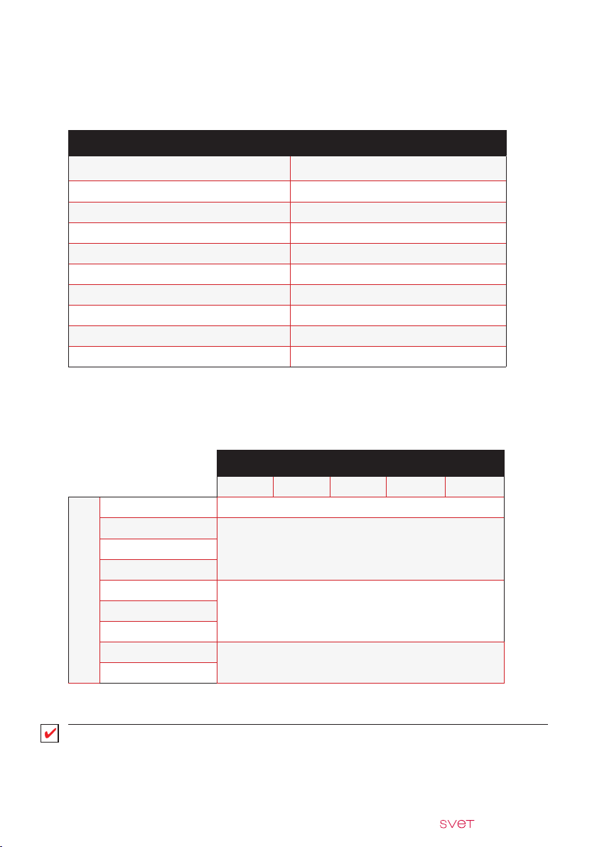
3.2 - Motor power table
Width [cm]
200 300 400 500 600
150 15/17 N/m
175
25 N/m200
225
250
Projections [cm]
300
325
350
30 N/m275
35 N/m
Tab.1
Tab.2
IMPORTANT
For this awning model it is not necessary to use motors with an electronic limit switch.
| ASSEMBLY | 7

3.3 - Table of cutting dimensions
Cutting dimensions
Component Type of control
NICE MOTOR L -120
NICE MOTOR WITH EMERGENCY MANOEUVRE L -120
Square
bar
Terminal bar
Roller
tube
Fabric
SOMFY MOTOR L -120
SOMFY MOTOR WITH EMERGENCY MANOEUVRE L -120
BECKER MOTOR L -120
BECKER MOTOR WITH EMERGENCY MANOEUVRE L -120
CRANK L -120
NICE MOTOR L -126
NICE MOTOR WITH EMERGENCY MANOEUVRE L -126
SOMFY MOTOR L -129
SOMFY MOTOR WITH EMERGENCY MANOEUVRE L -134
BECKER MOTOR L -129
BECKER MOTOR WITH EMERGENCY MANOEUVRE L -136
CRANK L -142
NICE MOTOR L -126
NICE MOTOR WITH EMERGENCY MANOEUVRE L -126
SOMFY MOTOR L -129
SOMFY MOTOR WITH EMERGENCY MANOEUVRE L -134
BECKER MOTOR L -129
BECKER MOTOR WITH EMERGENCY MANOEUVRE L -136
CRANK L -142
NICE MOTOR L -146
NICE MOTOR WITH EMERGENCY MANOEUVRE L -146
SOMFY MOTOR L -149
SOMFY MOTOR WITH EMERGENCY MANOEUVRE L -154
BECKER MOTOR L -149
BECKER MOTOR WITH EMERGENCY MANOEUVRE L -156
CRANK L -162
Cutting ratio
measurements in [mm]
Tab.3
8 | | ASSEMBLY
 Loading...