

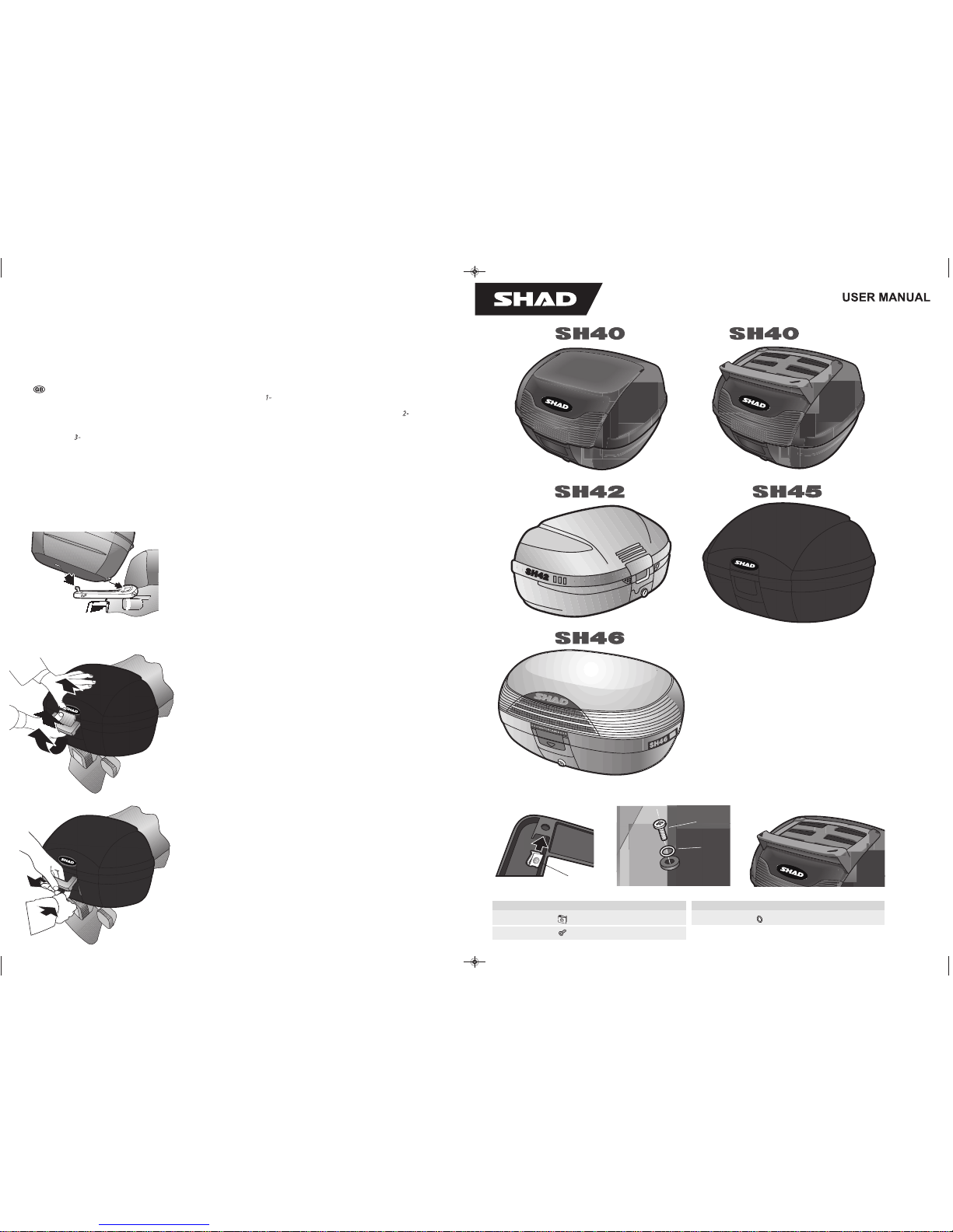
ASSEMBLY INSTRUCCIONS
Once the adaptor has been assembled you are then ready to t the TOP CASE. 1
- Put the key in and leave in the vertical position. Slot the rear
tongue into the adaptor groove. Fit the front anchorage into its housing. WARNING. It is important to ensure that the case is properly xed to the
adaptor. Make sure you hear the click of the pin as it goes in and that the front opening lever is correctly positioned (Fig. F). 2
- To open the
TOP CASE, insert the key in the vertical position. Operate the locking mechanism as shown in Fig. G. Turning the key in a clockwise direction will
lock the TOP CASE so that it can neither be opened nor detached from the adaptor. The key can be removed in either the locked o r unlocked
position. 3
- To remove the TOP CASE, insert the key in the vertical position, hold the case by the handle, operate the lower part of the ope ning
mechanism and lift up gently until the anchorage comes out of the case. Then pull to remove the upper tongue from the adaptor groove (Fig. H).
SH40-45-46
Fig. G
SH40-45-46
Fig. H
Fig. F
1.
SH40 CARGO
1
2
3
PARTS
.tnaC.feR.soP
48505031
42314032
.tnaC.feR.soP
44250023
The maximum load of the case is of:
SH40 - SH40 CARGO: 4 kg
SH42 - SH45 - SH46: 6 kg
CARGO
500791/1 user guide SH40_42_45_46 15/08/16 17:00 Página 1
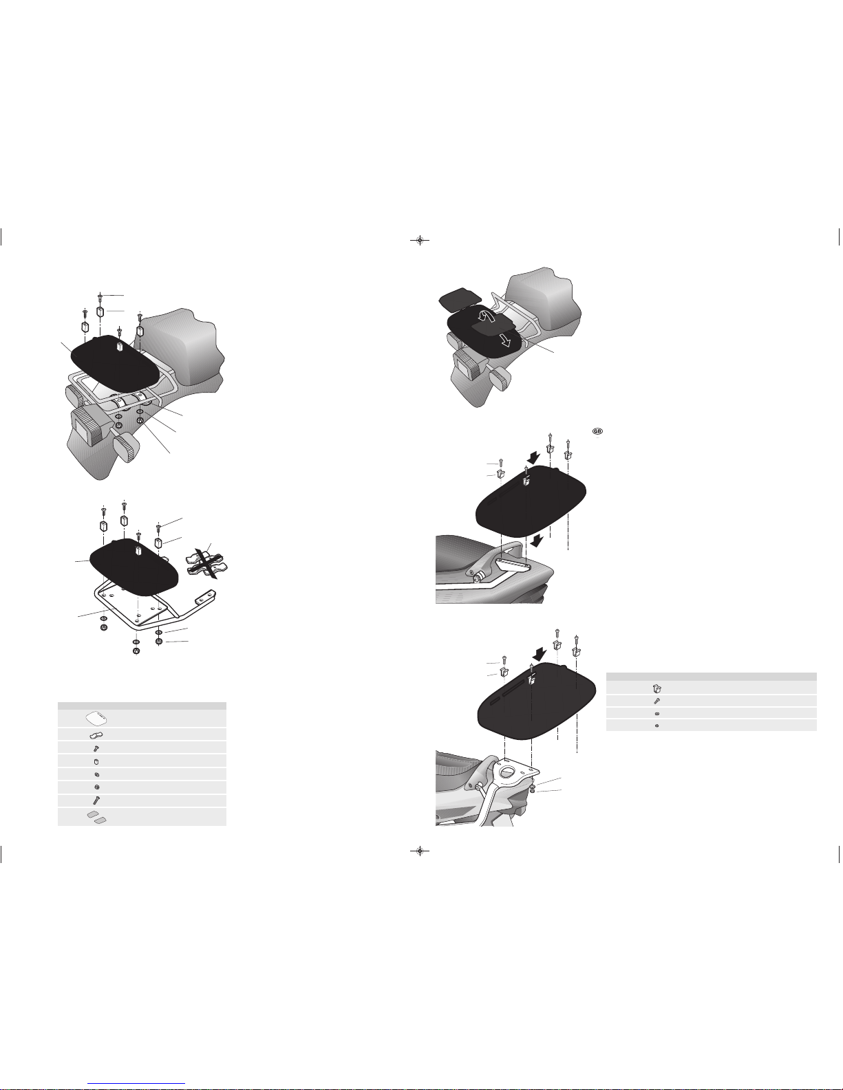
Fig. A: (*) Place the TOP CASE bottom rack (1) in the assembly
position(*)on the motorcycle original packet-holder, fit the
anchoring flanges (2) under the most suitable tubes or supports
and secure using the screws (3), the rectangular washers(4),
the flanges (2), the washers (5) and the nuts (6). Fig. B on the
SHAD anchoring: Situate the bottom rack of the TOP CASE (1) in
the assembly position, remove the fastening clips (2), fasten with
screws (7),the rectangular washers (4), the washers (5)
and the nuts (6). Tighten all the screws and nuts.
Fig. A
2
1
7
4
5
6
.tnaC.feR.soP
16051021
49401022
4)569 NID 04x6M( 4414033
4 2/3170024
4)6Ø( 0003035
4)6M( 1202036
4)569NID 03x6M( 8504037
1 805102/7051028
Fixation SHAD
PARTS
2.
Rack D1B40PA
11
12
10
9
8
Then fit the covers (8) by bending it slightly to insert the tongues
(Fig. C).
(*)
It can only be used on the Top or Full master.
(**)
Included in the specific support.
10
9
Fig. D
Fig. E
Fig. D: Fit the grille plate Top Case bottom rack on the Top kit sup- port
arms and secure it with the screws (10) and the washers (9).
Fig. E: Fit the grille plate Top Case bottom rack on the Top kit support
arms and secure it with the screws (10), the washers (9) and (11) and the
screws (12).
PARTS
.tnaC.feR.soP
4* 4051029
4** )219 02x8M( 47040301
4** )8Ø( 02030311
4** )8M( 42020321
Fig. C
3.
1
2
3
4
5
6
Fig. B
500791/1 user guide SH40_42_45_46 15/08/16 17:00 Página 3

Press Lock System
Change Colour System
Width: 56 / Height: 31 / Depth: 41
Maximum Load: 6
2 full face helmets
D1B40PA plate
included
Optional backrest
as an accessory
Optional brake light
as an accessory
Waterproof Sealing System
Find out more about luggage systems & saddlebags we have.
SHAD puts everything within reach.
 Loading...