

SG Wireless Communications Skyroute UT,Skyroute,Skyroute max Installation Manual
Skyroute
Skyroute UT
Skyroute max
WARNING:WARNING:
WARNING:
WARNING:WARNING:
before activating this unit. Call 1-888-251-7458 inbefore activating this unit. Call 1-888-251-7458 in
before activating this unit. Call 1-888-251-7458 in
before activating this unit. Call 1-888-251-7458 inbefore activating this unit. Call 1-888-251-7458 in
the U.S. or 1-888-955-5583 in Canadathe U.S. or 1-888-955-5583 in Canada
the U.S. or 1-888-955-5583 in Canada
the U.S. or 1-888-955-5583 in Canadathe U.S. or 1-888-955-5583 in Canada
You must be enrolled with Connect 24 You must be enrolled with Connect 24
You must be enrolled with Connect 24
You must be enrolled with Connect 24 You must be enrolled with Connect 24
Installation
Manual
Version 1.0
FCC COMPLIANCE STATEMENT
CAUTION
use this equipment.
This equipment has been tested and found to comply with the limits for a Class B digital device, pursuant to Part 15 and Part 22 of the
FCC Rules. These limits are designed to provide reasonable protection against har mful interference in a residential installation. This
equipment generates, uses and can radiate radio frequency energy and, if not installed and used in accordance with the instructions, may
cause harmful interference to radio communications. However, there is no guarantee that interference will not occur in a particular
installation. If this equipment does cause harmful interference to radio or television reception, which can be determined by turning the
equipment off and on, the user is encouraged to try to correct the interference by one or more of the following measures:
• Re-orient the receiving antenna.
• Increase the separation between the equipment and receiver.
• Connect the equipment into an outlet on a circuit different from that to which the receiver is connected.
• Consult the dealer or an experienced radio/television technician for help.
The user may find the following booklet prepared by the FCC useful: “How to Identify and Resolve Radio/Television Interference Prob-
lems”. This booklet is available from the U.S. Government Printing Office, Washington D.C. 20402, Stock # 004-000-00345-4.
: Changes or modifications not expressly approved by SG Wireless Communications could void your authority to
INDUSTRY CANADA COMPLIANCE STATEMENT
This Class B digital apparatus meets all requirements of the Canadian interference-causing equipment regulations.
Cet appareil numérique de la Classe B respecte toutes les exigences de règlement sur le matériel brouilleur du Canada.
WARNING:To satisfy FCC RF exposure requirements for fixed station transmitting
devices, a separation distance of 30 cm or more should be maintained
between the antenna of this device and persons during device operation. To
ensure compliance, operations at closer than this distance is not
recommended.

Table of Contents
Contents ii
Important Information ................................................. ii
Skyroute
Introducing the Skyroute
How the Skyroute
Installation 2
STEP 1 - Location of the Skyroute
Relocating the Antenna 3
Relocating the Skyroute
Skyroute
STEP 2 - Enrolling Skyroute
STEP 3 - Defaulting the Skyroute
max
Glossary of Terms ii
max
Transceiver 1
Specifications .............................................................. 1
Communications Method ............................................ 1
Dual Path Communications ......................................... 1
Antenna ....................................................................... 1
RF Power Output ......................................................... 1
Power Supply Ratings .................................................. 1
Dimension ................................................................... 1
Weight ......................................................................... 1
Operating Temperature .................................................. 1
max
Transceiver Works 1
Cellemetry Communication ............................................ 1
max
Mounting the Skyroute
Combus Connection ....................................................... 2
Bell IN Terminal ............................................................. 2
Bell OUT Terminal .......................................................... 2
Tamper Terminal ........................................................... 2
Secure Installation ......................................................... 2
Connection Diagram ...................................................... 2
Mounting the Antenna ................................................... 3
max
Transceiver Trouble Supervision 4
Transceiver .......................... 2
max
Unit 3
max
Transceiver 4
max
with 4020 4
max
Generic Reporting 5
Description ................................................................... 5
Normal Alarm Condition ................................................ 5
Notice .......................................................................... 5
STEP 4 - Programming Sections 6
Configuration Options - Section [006] ............................. 6
max
Skyroute
Skyroute
Test Transmission Day Mask - Section [011] .................... 6
STEP 5 - Activating the Skyroute
Calling Connect24 ......................................................... 6
Transmitting and Receiving ............................................. 6
Testing Your Control to the Central Station 6
Skyroute
[00][18]Skyroute
[00][18] Skyroute
[006]Skyroute max Configuration Options ....................... 7
[007Home SID Number .................................................. 7
[010]Skyroute max Test Time ......................................... 7
[011]Test Transmission Day Mask ................................... 7
[013]Skyroute max Test Rates ........................................ 7
Sections [030]-[047] ..................................................... 8
Skyroute max Transceiver Trouble Shooting 12
Antenna Relocation Diagram 13
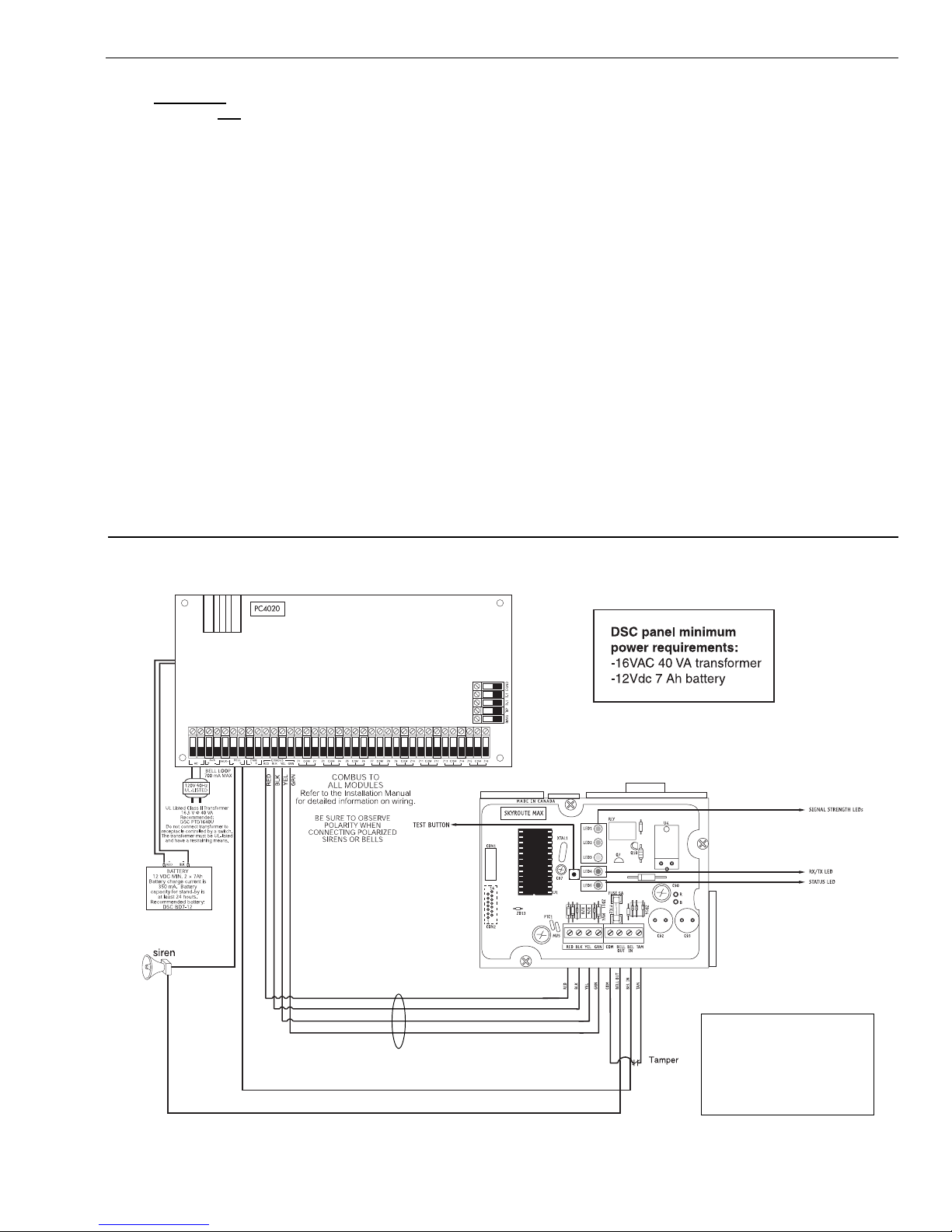
Supervised Power Supply Connection Diagram 14
Standard Connection with PC4020 15
For Your Records 16
Appendix A – Reporting Codes for SIA and Contact ID 17
Appendix B - Zone Reporting codes 18
Limited Warranty BACK
5
Transceiver SID (System ID) - Section [007] . 6
max
Test Time - Section [010] ........................... 6
max
Transceiver 6
max
Programming with PC4020
max
Programming 7
max
Programming .............................. 7
i

Contents
Important Information
This manual is based on the production version of the included
wireless device. Software changes may have occurred after the
revision of this manual.
Caution
Any changes or modifications not expressly approved in this
document could void your warranty for this equipment and void
your authority to use this equipment.
Skyroute
The following is a description of various terms used with
regards to cellemetry technology.
max
Tranceiver Glossary of Terms
Electronic Serial Number (ESN)
The ESN is used to carry data information in a Cellemetry
Network
Mobile Identification Number (MIN)
A 10 digit decimal number used for registrations and pages.
Page
A transmission that is sent from the Cellemetry Gateway to the
Cellemetry radio.
Warning
Only use the antenna provided by DSC / Sur-Gard. The use of any
other type will invalidate the warranty and may be dangerous.
Customer Service
For customer support please call Sur-Gard technical information
at 1-800-503-5869 or e-mail us at support@sur-gard.com.
Registration
A transmission that is sent from the Cellemetry radio to the
Cellemetry Gateway.
System Identification Number (SID)
Identification of the Cellemetry Provider.
Switch Number (SNO)
Switch number the Cellemetry radio uses to transmit pages to
the Cellemetry gateway.
Clearing House
The clearing house is a routing center that automatically forwards
data between Skyroute
max
transmitters and central stations.
ii

Introducing the Skyroute
max
Transceiver
The Skyroute
tion method for the transmission of event information using the
Cellemetry service. Events are transmitted from the Skyroute
transceiver via the Cellemetry network to the clearing house and
then to the Central Station in a fast, reliable manner. Skyroute
has been designed for simple and straightforward installation.
Using the Combus technology, wiring connections are made
directly between Skyroute
max
transceiver offers a new wireless communica-
max
and the security control panel.
max
max
Specifications
Compatible Control Panels
• DSC PC4020 software version v3.2 or higher
Communication Method
• AMPS Control Channel
Dual Path Communications
• The system can be used as the sole method of
communication to the monitoring station or as a dual
transmission path with the standard land line.
Please contact your monitoring station on
dual signal communication.
Antenna
• 3 dB gain, TNC connector
• Extension Kits available:
LAE – 3 The 3 Foot Antenna Kit for Skyroute
Transceiver
LAE – 15 The 15 Foot Antenna Kit for Skyroute
Transceiver
LAE – 25 The 25 Foot Antenna Kit for Skyroute
Transceiver
max
max
max
RF Power Output
• 3.0 Watts maximum
Power Supply Ratings
• 12 VDC @30mA, from Panel Combus
DC, from Bell Circuit
• 12 V
Current in Standby 90mA
Current when Receiving 135mA
Current when Transmitting 1.3A
For DSC PC4020 the required minimum transformer is a
•
16VAC 40 VA. The minimum Battery requirement is 12Vdc
7 Ah.
Dimension
• 3.5” x 4.6” x 1.8” (85 mm x 115 mm x 45 mm)
Weight
• 0.5 lbs. (0.2 kg)
Operating Temperature
•0oC - 49oC (32oF - 120oF)
• 90% humidity, non condensating
How the Skyroute
max
Transceiver Works
Cellemetry Communication
The Skyroute
channel of the existing cellular network. Signals are routed to the
Cellemetry gateway via the SS7 cellular network. A clearing house
then receives the signals and forwards the events to the central station.
max
transceiver communicates using the control
Upon receiving an acknowledgement signal from the central station,
the clearing house then returns a confirmation of delivery signal to the
max
Skyroute
see drawing below:
transceiver over the network. For transmission sequence
1
Installation
It is mandatory that the power be removed from the
system before any wiring changes are performed on the
Skyroute
damage to the Cellemetry modem.
Mounting the Skyroute
The Skyroute
hand corner of the panel’s cabinet through the knock out. The
Skyroute
through the use of clips and two screws.
Combus Connection
The Skyroute
yellow and green. Connect these four terminals to the 4 terminals
on the main control panel marked COMBUS (red, blk, yel and grn).
Bell IN Terminal
This terminal is used to power the cellemetry modem. This
connects to the BELL + on the control panel. No other wire should
be connected to the Bell+ of the control panel.
An extra power supply can be used to power the modem if it is
not located near the main control panel or where the
system cannot provide enough power for the transmissions. Connect the positive of the power supply to the BELL
IN and the negative to the COM to ensure proper grounding.
Bell OUT Terminal
This terminal is used to power the siren or any other devices
max
module. Neglecting to do so will result in
max
Transceiver
max
transceiver can be mounted in the upper right
max
transceiver case attaches to the panel’s cabinet
max
transmitter has 4 terminals marked red, black,
that would usually connect to the control panel BELL+
terminal. This output is powered through the 5A fuse for
protection of the radio transmitting power.
Tamper Terminal
Connect TAM and COM to a normally closed switch that will
be used to monitor tamper. If no tamper switch is desired, place
a wire between TAM and COM.
Secure Installation
For a secure installation, the Skyroute
its host panel must be locked and protected. An instant trip IR sensor
would be the most appropriate for supervision of the panel. A
cabinet tamper switch connected to the TAM terminal of the
Skyroute
max
transceiver is also suggested.
max
transceiver module and
Relocating the Antenna
If a suitable location is not available for proper Cellemetry
coverage, obtain an Antenna Extension Bracket kit from your
DSC/Sur-gard supplier. Each kit contains an extension
Connection Diagram
As indicated, the Skyroute
max
unit is a combus unit,
which can be located away
from the control when
required to provide
maximum signal strength.
2

STEP 1
Location of the Skyroute
It is very important to determine the best location for maximum signal strength.
Verify signal strength prior to installation!
+
12V 7Ah Battery12V 7Ah Battery
12V 7Ah Battery
12V 7Ah Battery12V 7Ah Battery
cable, a mounting bracket, instructions, and all required
hardware. Three lengths of extension cable are available:
max
-
Unit
LED 1: Good signal strength
LED 2: Acceptable signal strength
LED 3: Poor signal strength
LED 4: One blink = Transmit TX
Two blinks = Receive RX
LED 5: Status (number of blinks)
1: Normal (activated)
2: Radio not power-up
3: Failed self-test
4: No cell network
5: Fail to communicate
6: Ready to activate
8: Unit not enrolled with 4020
Extension Kit Length of cable
LAE-3 3 feet (0.91 m)
LAE-15 15 feet (4.57 m)
LAE-25 25 feet (7.62 m)
Only use the Extension Kits to extend the mounting range
of the antenna. Do not cut or splice the extension cable.
The maximum distance between the Skyroute
ceiver and the antenna is 25 feet (7.62 m) as obtained by
using the LAE-25 Extension Kit. Make sure the antenna is in
a physically secured location to avoid tampering.
Secure the TNC connector from the Extension Kit to the
mounting bracket, ensuring that the star washers make
solid electrical contact with the mounting bracket.
Remove the antenna from the Skyroute
connect the extension cable to the TNC connector on the
module. Secure the antenna to the TNC connector mounted
on the Extension Kit Mounting Bracket. Locate the mounting bracket and antenna away from possible sources of
electrical interference. Moving the antenna just a short
distance will likely be adequate. Temporarily secure the
mounting bracket in the new location and proceed with
max
max
module and
trans-
testing. If the test is successful, permanently secure the
mounting bracket and antenna at the new location.
Mounting the Antenna
NOTE: The antenna should always be attached to the
Skyroute max Transceiver for proper operation. The unit
will not function properly if the antenna is not installed.
3

Relocating the Skyroute
max
Transceiver
Since the Skyroute
panel when the panel is not located in a good cellemetry coverage area (a control panel installed in a vault for example). When relocating
the module, follow theses rules:
• Maximum of 1000 feet from the main control. Combus (Red, Black, Yellow, Green) from the panel to the Skyroute
transceiver.
• A supervised power supply
• The power supply (+ positive) is connected to the Skyroute
(–negative) to the Skyroute
• The cabinet must be installed in a secure location and should have a tamper circuit connected to the Skyroute
COM) terminals.
Skyroute
The Skyroute
board. LED5 normally flashes once every 2 seconds when the Skyroute
are indicated when LED5 flashes more than once every 2 seconds. Shown below is the number of flashes used to indicate each trouble
condition.
max
transceiver is a Combus accessory, it is possible to relocate the module up to 1000 feet from the main control
max
12V@1A (like the PC4204) must be used (see diagram on page 14).
max
transceiver (BELL IN) terminal and the power supply
max
transceiver (COM) terminal.
max
(TAM and
max
Transceiver Trouble Supervision
max
transceiver automatically monitors its operation and indicates trouble conditions by flashing LED5 on the circuit
max
transceiver is on stand-by (ready to transmit) mode. Troubles
Number Function of Flashes
of Flashes
1 Radio is operating normally
2 Radio is not powered, or not responding
3 Failed selftest
4 Service is not available
5 Failure to communicate
6 Ready to activate
8 Module not enrolled with panel
(1) Radio is operating normally: Skyroute
(2) Radio not powered or not responding: Skyroute
(3) Failed self-test: A self-test of the Cellemetry module has failed.
(4) Service not available: The Cellemetry modem has failed to register with the cellular network.
(5) Failure to communicate: A signal has not been successfully communicated to the central station.
(6) Not connected to clearing house: The Skyroute
(8) Module not enrolled with panel: The Skyroute
max
transceiver is ready to transmit.
max
transceiver initialization of Cellemetry modem has failed.
max
transceiver has not been activated.
max
transceiver is not addressed by the control panel.
STEP 2
Enrolling Skyroute
Once all the wiring is complete, you must enroll the module:
1. Enter installer’s programming by pressing [*][8][Installer’s Code]
2. Scroll to “Module Hardware” and press the [*] key.
3. Scroll to “Enroll Module” and press the [*] key.
4. Scroll through the different modules until “Alternate Comms” is displayed. Press the [*] key.
5. The message “Create Tamper on Desired Unit” will be displayed. To create the required tamper, secure the tamper zone on
the module and then open it. The transition from secure to violated enrolls the module. After this is done, the keypad will
display the module number and confirm enrollment “Alternate Comms Mod 01 Enrolled”.
For more information regarding module enrollment, see the control panel Installation Manual.
max
with PC4020
4
 Loading...