

SGS Thomson Microelectronics TS5070, TS5071N, TS5071, TS5070FN, TS5070FNTR Datasheet
PROGRAMMABLE CODEC/FILTER
COMPLETE CODEC AND FILTER SYSTEM
INCLUDING:
– TRANSMIT ANDRECEIVE PCM CHANNEL
FILTERS
– µ-LAW OR A-LAW COMPANDING CODER
AND DECODER
– RECEIVE POWER AMPLIFIER DRIVES
300 Ω
– 4.096 MHz SERIAL PCM DATA(max)
PROGRAMMABLE FUNCTIONS :
– TRANSMIT GAIN : 25.4 dB RANGE, 0.1 dB
STEPS
– RECEIVE GAIN : 25.4 dB RANGE, 0.1 dB
STEPS
– HYBRID BALANCE CANCELLATION FIL-
TER
– TIME-SLOT ASSIGNMENT: UP TO 64
SLOTS/FRAME
– 2 PORTASSIGNMENT (TS5070)
– 6 INTERFACELATCHES (TS5070)
–AORµ-LAW
– ANALOG LOOPBACK
– DIGITAL LOOPBACK
DIRECT INTERFACE TO SOLID-STATE
SLICs
SIMPLIFIES TRANSFORMER SLIC, SINGLE
WINDINGSECONDARY
STANDARDSERIALCONTROL INTERFACE
80 mW OPERATINGPOWER (typ)
1.5mWSTANDBYPOWER(typ)
MEETS OR EXCEEDS ALL CCITT AND
LSSGRSPECIFICATIONS
TTL AND CMOS COMPATIBLE DIGITAL IN-
TERFACES
DESCRIPTION
TheTS5070seriesarethesecondgenerationcombined PCM CODEC and Filter devices optimized
for digital switching applicationson subscriberand
trunk line cards.
Usingadvancedswitchedcapacitortechniquesthe
TS5070 and TS5071 combine transmit bandpass
and receive lowpass channel filters with a companding PCM encoder and decoder. The devices
are A-lawand µ-law selectableand employ a conventional serial PCM interface capable of being
clockedup to 4.096MHz.A numberofprogrammable functionsmay be controlled via a serial control
port.
TS5070
TS5071
COMBO 2
ORDERING NUMBER:TS5071N
ORDERING NUMBERS: TS5070FN
Channel gains are programmableover a 25.4 dB
range in each direction, and a programmablefilter
is included to enable Hybrid Balancing to be adjustedto suit a wide range of loop impedanceconditions.
Both transformerand activeSLIC interfacecircuits
with real or complex termination impedances can
be balanced by this filter, with cancellation in excessof 30 dBbeingreadilyachievablewhenmeasuredacrossthepassbandagainststandardtesttermination networks.
ToenableCOMBOIIG to interfaceto theSLICcontrol leads, a number of programmable latches are
included; each may be configuredas eitheran input or an output. The TS5070 provides 6 latches
and the TS5071 5 latches.
ND GENERATION
DIP20 (Plastic)
PLCC28
TS5070FNTR
December 1997
1/32
TS5070 - TS5071
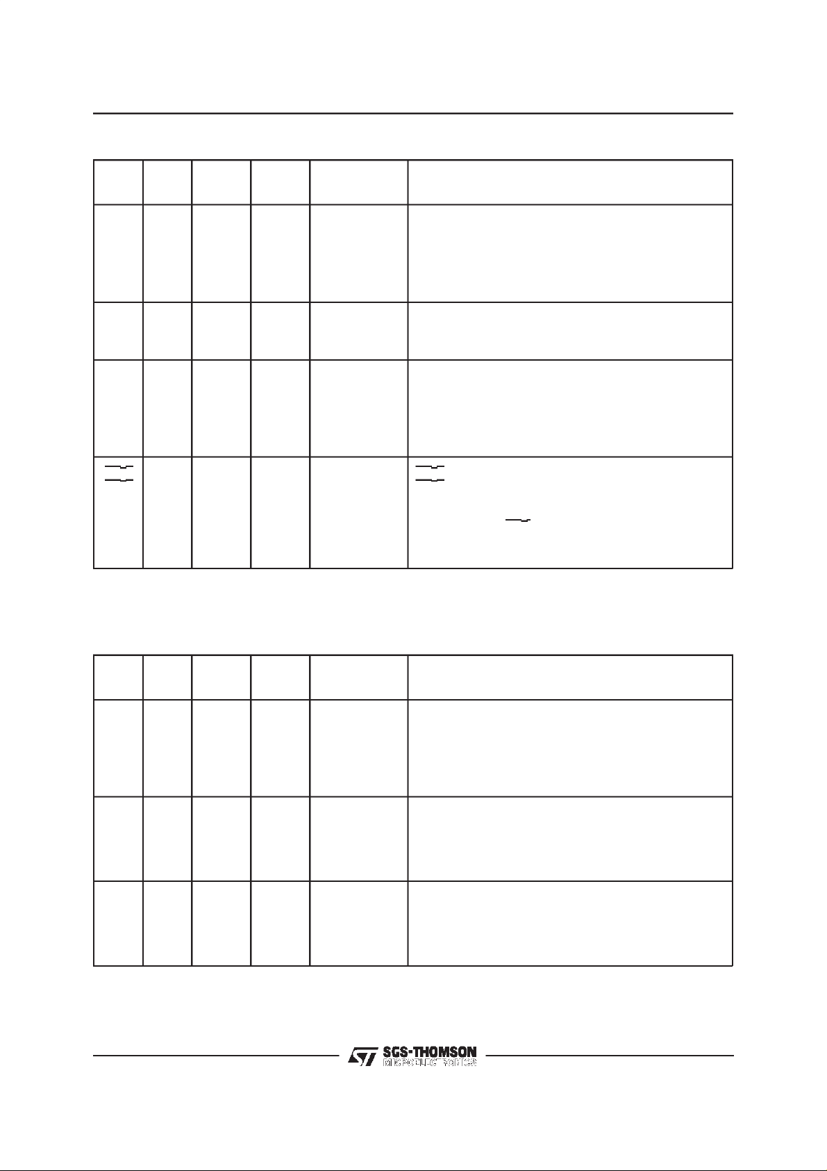
TS5070 PIN FUNCTIONALITY (PLCC28)
No. Name Function
1 GND Ground Input(+0V)
2VF
3V
4 NC Not Connected
5 NC Not Connected
6 IL3 Digital Input or Outputdefined by LDR register content
7 IL2 Digital Input or Outputdefined by LDR register content
8FS
9D
10 D
11 CO Digital output (shiftedout on CCLK rising edge)
12 CI Digital input (sampled on CCLK falling edge)
13 CCLK Digital input (clock)
14 CS Digital input (chip select forCI/CO)
15 MR Digital Input
16 BCLK Digital input (clock)
17 MCLK Digital input
18 D
19 D
20 TS
21 TS
22 FS
23 IL5 Digital input or output defined by LDR register content
24 IL4 Digital input or output defined by LDR register content
25 IL1 Digital input or output defined by LDR register content
26 IL0 Digital input or output defined by LDR register content
27 V
28 VF
0 Analog Output
R
SS
R
1 Digital input sampled by BCLK falling edge
R
0 Digital input sampled by BCLK falling edge
R
0 Digital output clocked by BCLK rising edge
X
1 Digital output clocked by BCLK rising edge
X
X
X
X
CC
X
Supply Input(-5V)
Digital input
0 Open drain output (pulled low by active DX0 time slot)
1 Open drain output (pulled low by active DX1 time slot)
Digital input
Supply input (+5V)
I Analog input
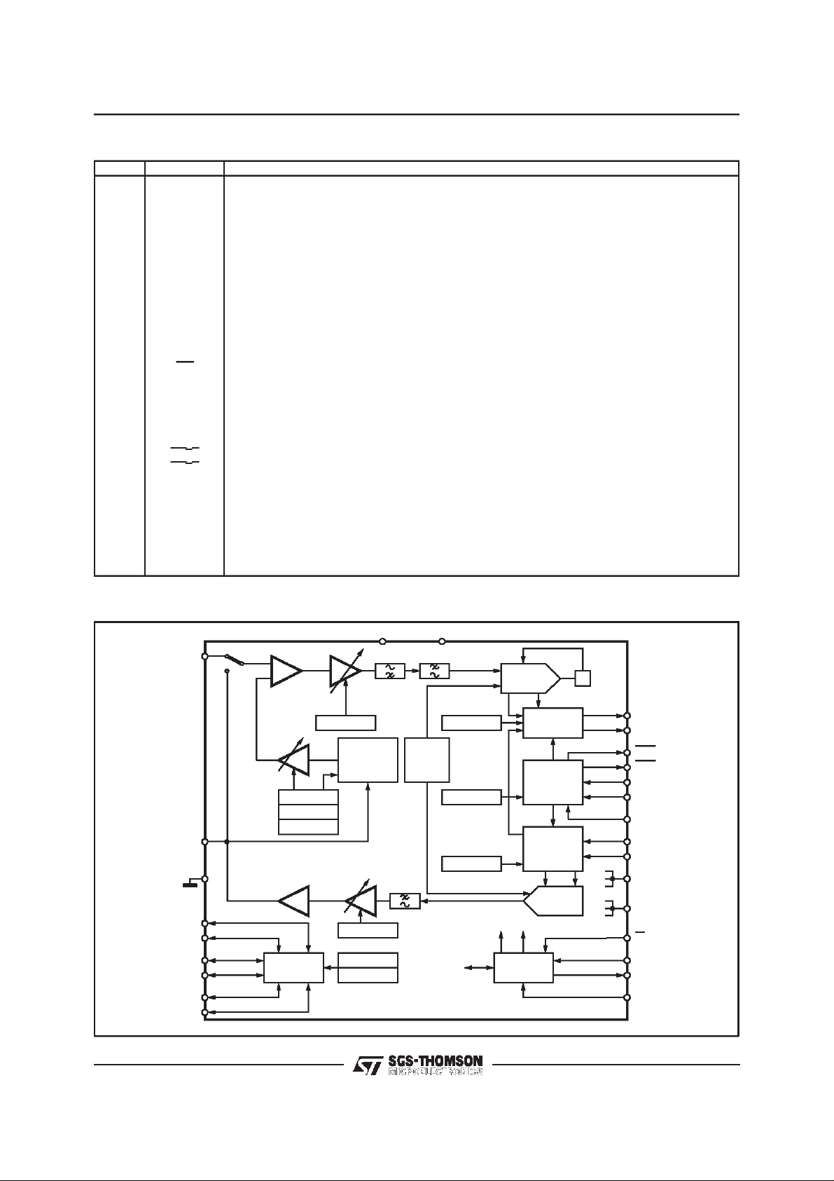
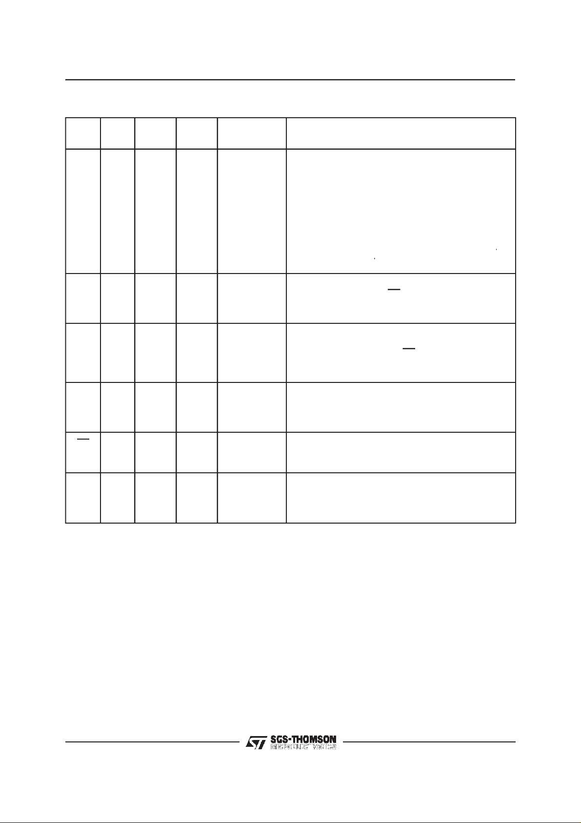
TS5070 FUNCTIONALDIAGRAM
VFXI
HYBAL 1
HYBAL 2
HYBAL 3
VFRO
GND
IL5
IL4
IL3
IL2
IL1
IL0
TS5070/71
INTERFACE
LATCHES
TX GAIN
HYBRID
BALANCE
FILTER
RX GAIN
LATCH DIR
LATCH CONT.
VSS=-5VVCC=+5V
Vref
TX TIME SLOT
CTL REG.
RX TIME SLOT
ENCODER
REGISTER
TIME-SLOT
ASSIGNMENT
REGISTER
DECODER
CONTROL
INTERFACE
D94TL135
TX
RX
AZ
DX0
DX1
TSX0
TSX1
FSX
BCLK
FSR
DR0
DR1
MCLK
MR
CS
CCLK
CO
CI
2/32
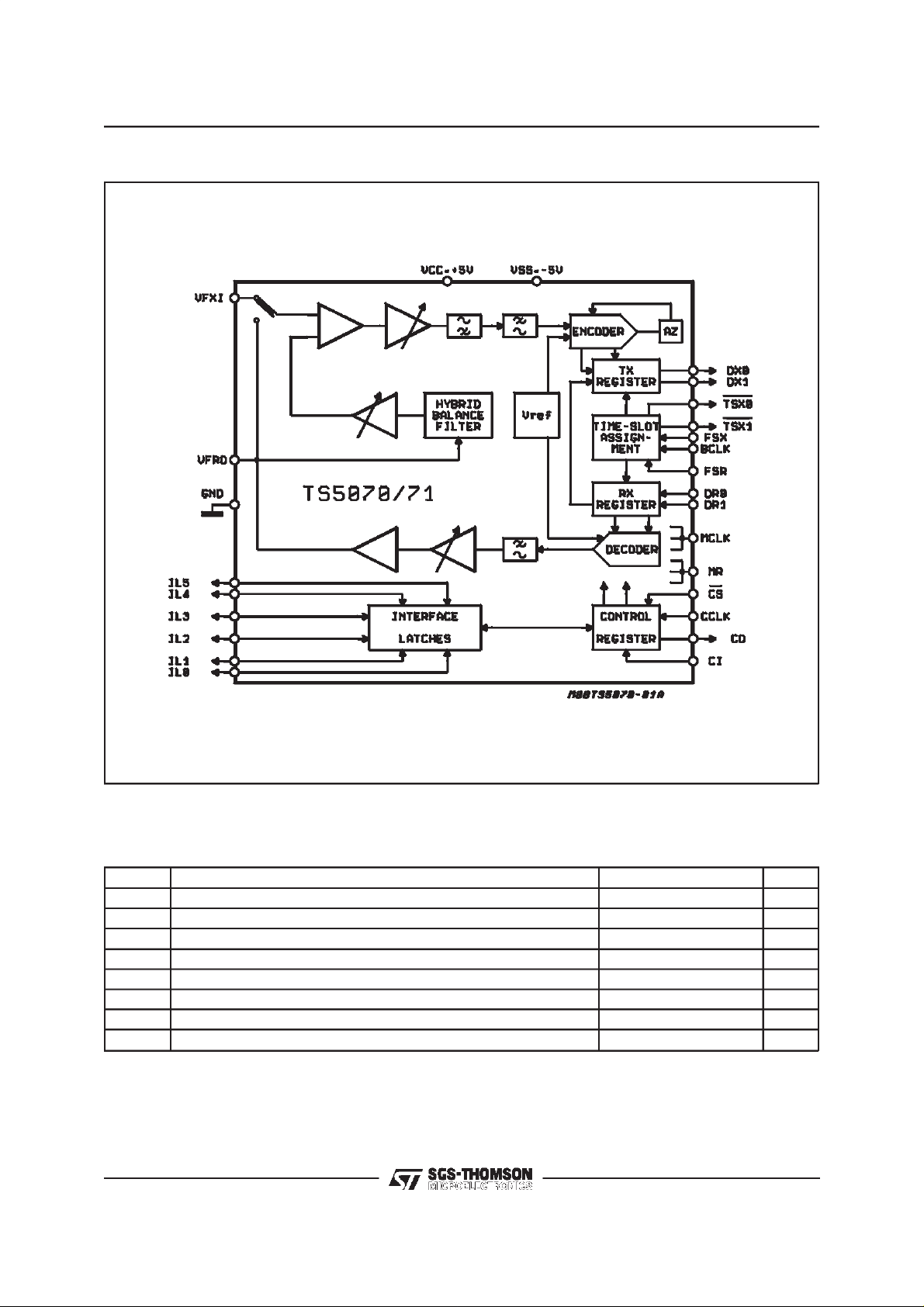
BLOCK DIAGRAM
TS5070 - TS5071
ABSOLUTE MAXIMUM RATINGS
Symbol Parameter Value Unit
V
V
V
I
T
T
lead
VCCto GND 7 V
CC
VSSto GND – 7 V
SS
Voltage at VFXI V
Voltage at Any Digital Input VCC+ 0.5 to GND – 0.5 V
IN
+ 0.5 to VSS– 0.5 V
CC
Current at VFRO ± 100 mA
Current at Any DigitalOutput ± 50 mA
O
Storage Temperature Range – 65, + 150 °C
stg
Lead Temperature Range (soldering, 10 seconds) 300 °C
3/32
TS5070 - TS5071
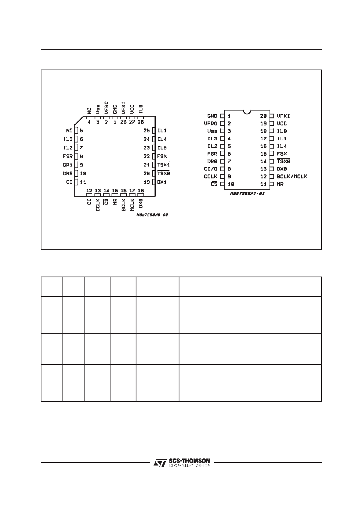
PIN CONNECTIONS
PLCC28
TS5070FN
DIP20
TS5071N
POWERSUPPLY, CLOCK
Name
V
CC
V
GND
BCLK I 16 12 Bit Clock Bit clockinput used to shift PCM data into and out of the
MCLK I 17 12 Master Clock Master clock input used by the switched capacitor filters
Pin
Type
SS
TS5070FNTS5071
S
S
S
27
N
19
3
1
3
1
Function Description
Positive Power
Supply
Negative
Power Supply
Ground
+5V±5%
–5V±5%
All analog and digital signals are referenced to this pin.
and DXpins. BCLK may vary from 64 kHz to 4.096
D
R
MHz in 8 kHz increments, andmust be synchronous with
MCLK (TS5071 only).
and the encoder and decoder sequencing logic. Must be
512 kHz, 1. 536/1. 544 MHz,
2.048 MHz or 4.096 MHz and synchronous with BCLK.
BCLK and MCLK arewired together in the TS5071.
4/32
TRANSMITSECTION
TS5070 - TS5071
Name
FS
VF
D
D
TS
TS
Pin
Type
X
I I 28 20 Transmit
X
0
X
1
X
0
X
1
X
TS5070FNTS5071
N
I 22 15 Transmit
0
0
0
0
18
19
20
21
13
–
14
–
Function Description
Normally apulse or squarewave waveform with an 8 kHz
Frame Sync.
repetition rate is applied to this input to definethe startof
the transmit time-slot assigned to this device (non-delayed
data mode) or the start of the transmit frame (delayed
data mode using the internal time-slot assignment
counter).
This is a high–impedance input. Voice frequency signals
Analog
present on this input are encoded as an A–law or µ–law
PCM bit stream and shifted out on the selected D
Transmit Data D
1 is available on the TS5070 only, DX0 is available on
X
all devices. These transmit data TRI–STATEoutputs
remain in the high impedance state except during the
assigned transmit time–slot on the assigned port, during
which the transmit PCM data byte is shifted out on the
rising edges of BCLK.
Transmit
Time–slot
1 is available on the TS5070 only.
TS
X
TS
0 is available on all devices. Normally these opendrain
X
outputs are floating in a high impedance state except
when a time–slot is activeon one of the D
the apppropriate TS
output pulls low to
X
enable a backplane line–driver. Should be strapped to
ground (GND) when not used.
pin.
X
outputs, when
X
RECEIVESECTION
Name
FS
VF
D
D
Pin
Type
R
0 0 2 2 Receive Analog The receive analog power amplifier output, capable of
R
0
R
1
R
TS5070FNTS5071
N
Function Description
I 8 6 Receive Frame
Sync.
I
I
10
7
9
Receive Data D
–
Normally apulse or squarewave waveform with an 8 kHz
repetition rate is applied to this input to definethe startof
the receive time–slot assigned to this device (non-delayed
frame mode) or the startof the receive frame (delayed
frame mode using the internal time-slot assignment
counter.
driving load impedances as low as 300Ω(depending on
the peak overload levelrequired). PCM data received on
the assigned D
pin is decoded and appears at this output
R
as voice frequency signals.
1 is availableon the TS5070 only, DR0 isavailable on
R
all devices. These receive data input(s) are inactive
except during the assigned receive time–slot of the
assigned port when the receive PCM data is shifted inon
the falling edges of BCLK.
5/32
TS5070 - TS5071
INTERFACE, CONTROL, RESET
Name
IL5
IL4
IL3
IL2
IL1
IL0
CCLK I 13 9 Control Clock This clock shifts serial control information into or out of CI
CI/O I/O – 8 Control Data
CI
CO
Pin
Type
TS5070FNTS5071
I/O
I/O
I/O
I/O
I/O
I/O
I
O
23
24
25
26
12
11
N
–
16
6
7
4
5
17
18
–
–
Function Description
Interface
Latches
Input/output
Control Data
Input
Control Data
Output
IL5 throughIL0 are available on the TS5070,
IL4 throughIL0 are available on the TS5071.
Each interfaceLatch I/O pin may be individually
programmed as an input or an output determined by the
state of the corresponding bit in the Latch Direction
Register (LDR) . For pins configured as inputs, thelogic
state sensed on each input is latched into the interface
Latch Register (ILR) whenever control data is written to
COMBO IIG, while CS is low, and the information is
shifted out on the CO (or CI/O) pin. Whenconfigured as
outputs, control data written into the ILR appears at the
corresponding IL pins.
or CO (or CI/O) when the CS input is low depending on
the currentinstruction. CCLK may be asynchronous with
the othersystem clocks.
This is Control Data I/O pin wich is provided on the
TS5071. Serial control information is shifted into orout of
COMBO IIG on this pinwhen CS is low. The directionof
the datais determined by the current instruction as defined
in Table 1.
These are separate controls, availables only on the
TS5070. They can be wired together if required.
CS I 14 10 Chip Select When this pins is low, control information can be written to
MR I 15 11 Master Reset This logicinput must be pulled lowfor normal operation of
FUNCTIONAL DESCRIPTION
POWER-ONINITIALIZATION
When power is first applied, power-on reset cir-
cuitry initializes COMBO IIG and puts it into the
power-down state. The gain control registers for
the transmit and receive gain sections are programmed for no output, the hybrid balance circuit
is turned off, the power amp is disabled and the
device is in the non-delayed timing mode. The
Latch Direction Register (LDR) is pre-set with all
IL pins programmed as inputs, placing the SLIC
interface pins in a high impedance state. The
or readfrom the COMBO IIG via the CI and CO pins (or
CI/O).
COMBO IIG. When pulled momentarily high, all
programmable registers in the device are resetto the
states specified under ”Power–on Initialization”.
CI/O pin is set as an input ready for the first control byte of the initializationsequence.Other initial
states in the Control Register are indicated in Table 2.
Aresetto thesesameinitialconditionsmayalsobe
forcedby drivingtheMR pinmomentarilyhigh. This
maybedone eitherwhenpowered-upor down.For
normaloperationthispin must be pulledlow. If not
used,MR shouldbe hard-wired to ground.
The desired modesforall programmablefunctions
may be initialized via the control port prior to a
Power-upcommand.
6/32

TS5070 - TS5071
POWER-DOWN STATE
Following a period of activity in the powered-up
state the power-down state may be re-entered by
writing any of the control instructionsinto the serial
control port with the ”P” bit set to ”1” It is recommendedthat thechipbepowereddownbefore writing any additional instructions. In the power-down
state, all non-essential circuitry is de-activated and
0andDX1outputsarein the highimpedance
theD
X
TRI-STATEcondition.
Thecoefficientsstoredin theHybridBalancecircuit
and the Gain Controlregisters,the data in the LDR
and ILR, and all control bits remain unchanged in
the power-down state unless changed by writing
new data via the serialcontrolport,whichremains
operational. The outputs of the Interface Latches
also remainactive, maintaining the ability to monitor and control a SLIC.
TRANSMITFILTERAND ENCODER
The Transmitsection input, VF
I, is a high imped-
X
ance summinginputwhichis usedas thedifferencingpointfortheinternalhybridbalancecancellation
signal. No external componentsare needed to set
the gain. Following this circuit is a programmable
gain/attenuationamplifierwhichiscontrolledbythe
contents of the Transmit Gain Register (see Programmable Functions section). An active prefilter
then precedesthe 3rd order high-pass and 5th order low-pass switched capacitor filters. The A/D
converterhas acompressingcharacteristicaccording to the standard CCITT A orµ255 coding laws,
whichmustbe selectedbya controlinstructionduring initialization(see table 1 and 2). A precisiononchipvoltagereferenceensuresaccurateand highly
stable transmissionlevels. Any offset voltage arising in the gain-set amplifier, the filters or the comparatoris cancelledbyaninternalauto-zerocircuit.
Each encode cycle begins immediately following
the assigned Transmit time-slot. The total signal
delay referencedto the start of thetime-slot is approximately 165µs (due to the Transmit Filter)
plus 125 µs (due to encoding delay), which totals
290 µs. Data is shifted out on D
0orDX1 during
X
the selected time slot on eight rising edges of
BCLK.
Register,isincluded,andfinallyaPost-Filter/Power
Amplifier capable of driving a 300Ωload to±3.5
V, a 600 Ω load to ± 3.8 Vor 15 kΩ loadto ± 4.0 V
at peakoverload.
A decode cycle begins immediately after each receive time-slot, and 10µs later the Decoder DAC
output is updated. The total signal delay is 10µs
plus 120 µs (filter delay) plus 62.5 µs (1/2 frame)
whichgives approximately190 µs.
PCM INTERFACE
TheFS
and FSRframe syncinputsdeterminethe
X
beginning of the 8-bit transmit and receive timeslots respectively. They may have any duration
from a single cycle of BCLK to one MCLK period
LOW. Two different relationships may be establishedbetweentheframesyncinputsandtheactual
time-slotson thePCMbussesby settingbit 3 inthe
Control Register (see table 2). Non delayed data
mode is similar to long-frame timing on the
ETC5050/60 series of devices : time-slots being
nominallycoincident with the rising edge ofthe appropriate FS input. The alternative is to use Delayed Data mode which is similar to short-frame
sync timing, in which each FS input must be high
at least a half-cycleof BCLK earlier than the timeslot.
TheTime-SlotAssignmentcircuit onthedevicecan
onlybeusedwithDelayedDatatiming.Whenusing
Time-Slot Assignment, the beginning of the first
time-slot in a frameis identified by the appropriate
FSinput.Theactualtransmitandreceivetime-slots
are then determined by the internalTime-Slot Assignment counters. Transmit and Receive frames
and time-slots may be skewedfrom each other by
any number of BCLK cycles.
During each assigned transmit time-slot, the selected D
register on the rising edges of BCLK. TS
TS
0/1 output shifts data out from the PCM
X
1 as appropriate)also pulls low for the first 7
X
0 (or
X
1/2 bit times of the time-slot to control the TRISTATE Enable of a backplane line driver. Serial
PCM data is shifted into the selected D
0/1 input
R
during each assigned Receive time slot on the
falling edges of BCLK. D
1 are selectableon the TS5070 only.
D
R
0orDX1 and DR0or
X
DECODERAND RECEIVE FILTER
PCM data is shifted into the Decoder’s Receive
PCMRegistervia theD
0orDR1pinduringthe se-
R
lectedtime-slotonthe8fallingedgesofBCLK.The
Decoder consistsof an expandingDAC with either
Aorµ255law decodingcharacteristic, which is selectedby thesamecontrolinstructionusedtoselect
the Encode law during initialization. Following the
Decoderisa 5thorder low-passswitched capacitor
filter with integral Sin x/x correction for the 8 kHz
sample and hold. A programmablegain amplifier,
which must be set by writing to the Receive Gain
SERIALCONTROL PORT
Control information and data are written into or
readback from COMBO IIG via the serial control
portconsistingof the controlclockCCLK; theserial
data input/output CI/O (or separate input CI, and
output CO on the TS5070only); and the ChipSelect input CS. All control instructions require 2
bytes,as listedintable1, withtheexceptionof asingle bytepower-up/downcommand. Thebyte1bits
are used as follows: bit 7 specifies power-up or
power-down;bits 6, 5, 4 and 3 specifythe register
address; bit 2 specifies whetherthe instructions is
read or write; bit 1 specifies a one or two byte in-
7/32

TS5070 - TS5071
struction;and bit0 is not used.Toshiftcontroldata
into COMBO IIG, CCLK must be pulsed high 8
timeswhile CS is low. DataontheCI or CI/Oinput
is shifted into the serial input registeron the falling
edge of each CCLK pulse. After all data is shifted
in, the contentsof the input shift register are decoded, and may indicate that a 2nd byte of control
data willfollow.Thissecondbyte mayeitherbe definedby asecondbyte-wideCSpulseormayfollow
the firstcontinuously,i.e. it isnotmandatoryfor CS
to returnhigh in betweenthe first and secondcontrol bytes.Onthefalling edgeofthe8
th
CCLKclock
pulse in the 2nd controlbytethedataisloadedinto
theappropriateprogrammableregister.CSmayremain low continuouslywhen programmingsucces-
siveregisters,ifdesired.HoweverCS shouldbe set
high when no data transfersare in progress.
ToreadbackinterfaceLatch dataor statusinformationfromCOMBOIIG,thefirstbyteofthe appropriateinstructionisstrobedinduringthe firstCSpulse,
asdefinedin table1.CS must thenbetakenlowfor
a further 8 CCLK cycles, during which the data is
shiftedontotheCO or CI/O pin on therisingedges
of CCLK. When CS ishighthe CO or CI/Opin is in
thehigh-impedanceTRI-STATE,enablingtheCI/O
pins of many devices to be multiplexed together.
Thus, to summarize, 2-byte READ and WRITE instructionsmay use eithertwo 8-bit wideCSpulses
or a single 16-bit wide CS pulse.
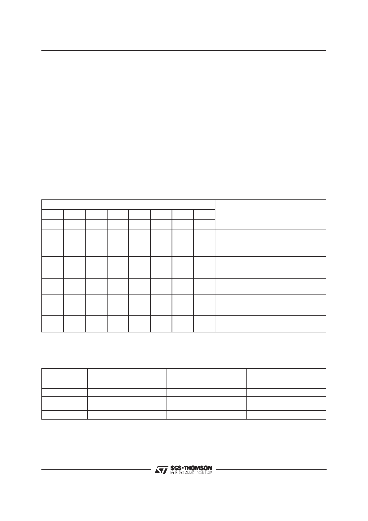
Table 1: ProgrammableRegister Instructions
Function
76543210
Single Byte Power–up/down PXXXXX0X None
Write Control Register
Read–back Control Register
Write Latch Direction Register (LDR)
Read Latch Direction Register
Write Latch Content Register (ILR)
Read Latch Content Register
Write Transmit Time–slot/port
Read–back Transmit Time–slot/port
Write Receive Time–slot/port
Read–back Receive Time–slot/port
Write Transmit Gain Register
Read Transmit Gain Register
Write Receive Gain Register
Read Receive Gain Register
Write Hybrid Balance Register ≠ 1
Read Hybrid Balance Register ≠ 1
Write Hybrid Balance Register≠2
Read Hybrid Balance Register ≠ 2
Write Hybrid Balance Register ≠ 3
Read Hybrid Balance Register≠3
PP000000000111X
PP000011000111X
PP000000110111X
PP110011000111X
PP110000110111X
PP001100110111X
PP001100000111X
PP001111000111X
PP001111110111X
PP110000000111X
Byte 1
X
X
X
X
X
X
X
X
X
X
See Table 2
See Table 2
See Table 4
See Table 4
See Table 5
See Table 5
See Table 6
See Table 6
See Table 6
See Table 6
See Table 7
See Table 7
See Table 8
See Table 8
See Table 9
See Table 9
See Table 10
See Table 10
Byte 2
Notes: 1. Bit 7 of bytes 1 and 2 is always the first bit clocked into or out of the CI, CO or CI/CO pin.
PROGRAMMABLE FUNCTIONS
POWER-UP/DOWN CONTROL
Following power-on initialization, power-up and
power-down control may be accomplished by
writing any of the control instructions listed in table 1 into COMBO IIG with the ”P” bit set to ”0”
for power-up or ”1” for power-down. Normally it is
recommendedthat all programmable functions be
initially programmed while the device is powered
down. Power state control can then be included
with the last programming instruction or the sepa-
8/32
2. ”P” is the power-up/down control bit, see ”Power-up” section (”0” = Power Up ”1” = Power Down).
rate single-byte instruction. Any of the programmable registers may also be modified while the
device is powered-up or down be setting the ”P”
bit as indicated.When the power up or down control is entered as a single byte instruction, bit one
(1) must be set to a 0.
When a power-up command is given, all de-activated circuits are activated, but the TRI-STATE
PCM output(s), D
0 (and DX1), will remain in the
X
high impedance state until the second FS
after power-up.
X
pulse
TS5070 - TS5071
CONTROLREGISTERINSTRUCTION
The first byte of a READ or WRITE instruction to
the Control Register is as shown in table 1. The
second byte functionsare detailed in table 2.
MASTER CLOCKFREQUENCY SELECTION
A Master clock must be provided to COMBO IIG
for operation of the filter and coding/decoding
functions. The MCLK frequency must be either
512 kHz, 1.536 MHz, 1.544 MHz, 2.048 MHz, or
4.096 MHz and must be synchronouswith BCLK.
Bits F1 and F0 (see table 2) must be set during
initializationto selectthe correctinternal divider.
ANALOGLOOPBACK
Analog Loopback mode is entered by setting the
”AL”and”DL” bits in theControl Registeras shown
in table2. In the analogloopbackmode,theTransmit input VF
ternally connected to the VF
loop from the Receive PCM Register back to the
TransmitPCM Register.The VF
tive, and the programmed settings of the Transmit
and Receive gains remain unchanged, thus care
must be taken to ensure that overload levels are
notexceededanywherein theloop.
Hybrid balancing must be disabled for meaning
ful analogloopbackFunction.
CODINGLAW SELECTION
Bits ”MA” and ”IA” in table 2 permit the selection
of µ255 coding or A-law coding with or without
even-bit inversion.
DIGITALLOOPBACK
Digital Loopback mode is entered by setting the
”DL”bitintheControlRegisterasshownintable2.
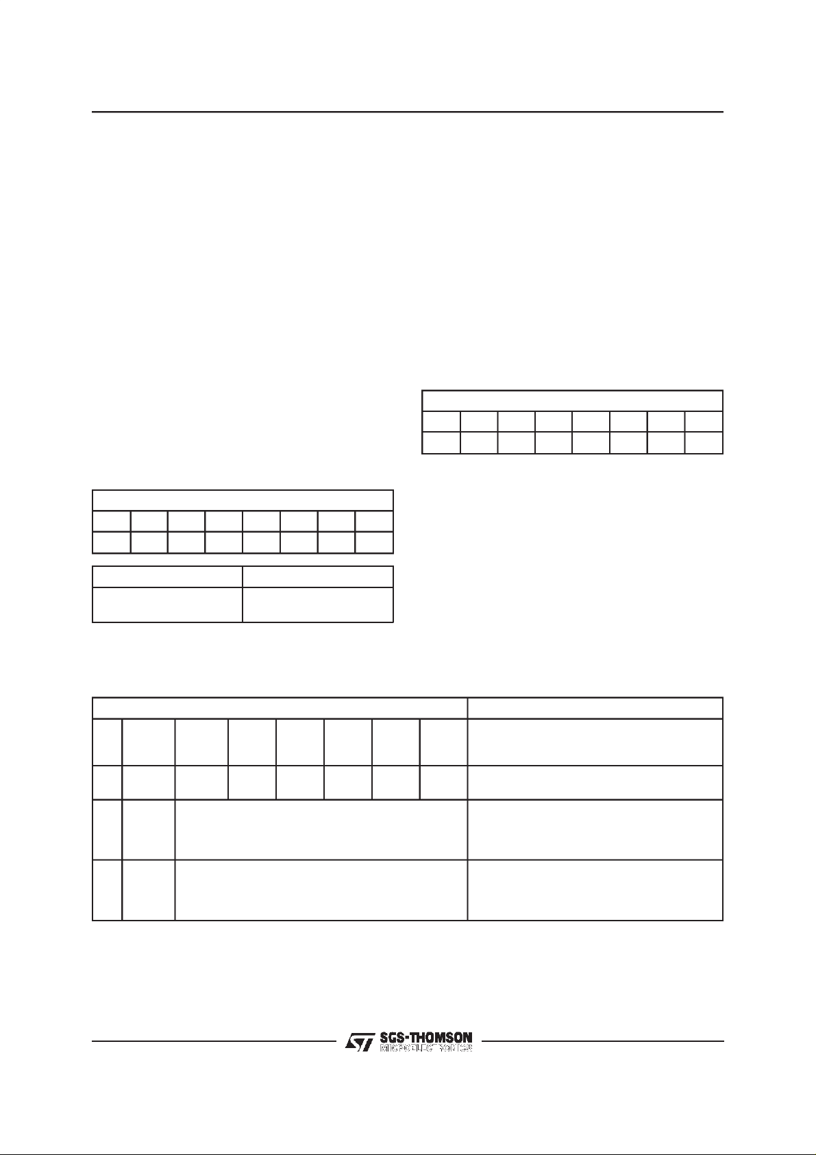
Table 2: ControlRegister Byte 2 Functions
Bit Number
76543210
F1 F0 MA IA DN DL AL PP
0
0
1
1
0
1
0
1
0
1
1
X
0
1
0
1
0
1
0
0
X
1
I is isolatedfromthe inputpin and in-
X
Function
MCLK = 512kHz
MCLK = 1.536 or 1. 544 MHz
MCLK = 2.048 MHz
MCLK = 4.096 MHz
Select µ. 255 Law
A–law, Including Even Bit Inversion
A–Law, No Even Bit Inversion
Delayed Data Timing
Non–delayed Data Timing
Normal Operation
Digital Loopback
Analog Loopback
0
Power Amp Enabled in PDN
1
Power Amp Disabled in PDN
*
*
O output, forming a
R
O pin remainsac-
R
*
*
*
(*) State at power-on initialization (bit 4 = 0)
Table 3: Coding Law Conventions.
m255 Law
MSB LSB
V
= +Full Scale 100000001010101011111111
IN
=0V 10111111111111111011001100110011100000000000000
V
IN
V
= -Full Scale 000000000010101001111111
IN
Note: The MSB is always the first PCM bitshifted in or out ofCOMBO IIG.
True A-law with
even bit inversion
MSB LSB
A-law without
even bit inversion
MSB LSB
0
9/32
TS5070 - TS5071
This mode provides another stage of path verificationby enablingdata written into the ReceivePCM
Register to be read back from that register in any
Transmittime-slotat D
0orDX1.
X
For Analog Loopback as well as for Digital Loopback PCM decoding continues and analog output
appears at VF
O. The output can be disabled by
R
pro gramming ”No Output” in the Receive Gain
Register (see table 8).
INTERFACELATCHDIRECTIONS
Immediately following power-on, all Interface
Latches assume they are inputs, and therefore all
IL pins are in a high impedance state. Each IL pin
maybe individuallyprogrammedasa logicinputor
output by writing the appropriateinstructionto the
LDR, see table 1 and 4. Bits L
must be set by
5-L0
writing the specific instruction to the LDR with the
L bits in thesecondbyte setasspecifiedin table4.
Unused interface latches should be programmed
as outputs.For the TS5071, L5 should always be
programmedas an output.
Table4: Byte2 Functionof LatchDirection Register
Bit Number
76543210
L0 L1 L2 L3 L4 L5 X X
LNBit IL Direction
0
1
(*) State atpower-on initilization.
Note: L5 should be programmed as an output for the TS5071.
Input
Output
*
INTERFACE LATCH STATES
Interface Latches configured as outputs assume
the state determinedby theappropriate data bit in
the 2-byte instruction written to the Latch Content
Register (ILR) as shown in tables 1 and 5.
Latches configured as inputs will sense the state
applied by an external source, such as the OffHook detect output of a SLIC. All bits of the ILR,
i.e. sensed inputs and the programmed state of
outputs, can be read back in the 2nd byte of a
READ from the ILR. It is recommended that, during initialization, the state of IL pins to be configured as outputs should first be programmed, followed immediately by the Latch Direction
Register.
Table 5: Interface LatchData Bit Order
Bit Number
76543210
D0 D1 D2 D3 D4 D5 X X
TIME-SLOTASSIGNMENT
COMBOIIGcan operatein eitherfixedtime-slotor
time-slotassignmentmodeforselectingthe Transmitand ReceivePCM time-slots.Followingpoweron,the deviceis automaticallyinNon-DelayedTimingmode,in whichthe time-slotalwaysbegins with
the leading (rising) edge of frame sync inputsFS
and FSR. Time-SlotAssignment may only be used
with Delayed Data timing : see figure 6. FS
FS
may have any phase relationship with each
R
X
and
other in BCLKperiod increments.
X
Table 6: Byte 2 of Time-slotand Port Assignment Instructions
Bit Number Function
7
EN
0X X XXXXX
10
11
Notes:
1. The ”PS” bit MUST always be set to 0 for theTS5071.
2. T5 is the MSB of thetime-slot assignment.
(*) State at power-on initialization
10/32
6
PS
(note 1)
5
T5
(note 2)
Assign One Binary CodedTime-slot from0–63
Assign One Binary CodedTime-slot from0–63
Assign One Binary CodedTime-slot from0–63
Assign One Binary CodedTime-slot from0–63
4
T4
3
T3
T2
2
1
T1
0
T0
Disable D
Disable D
Enable D
(Transmit instruction)
Enable D
(Receive Instruction)
Enable D
(Transmit instruction)
Enable D
(Receive Instruction)
Outputs (transmit instruction) *
X
Inputs(receive instruction) *
R
0 Output,Disable DX1 Output
X
0 Input, Disable DR1 Input
R
1 Output,Disable DX0 Output
X
1 Input, Disable DR0 Input
R
 Loading...