

SGS Thomson Microelectronics TIP2955, TIP3055 Datasheet
TIP2955
®
TIP3055
COMPLEMENTARY SILICON POWER TRANSISTORS
■
STMicroelectronics PREFERRED
SALESTYPES
■
COMP LEMENTA R Y P N P - NPN DEVICES
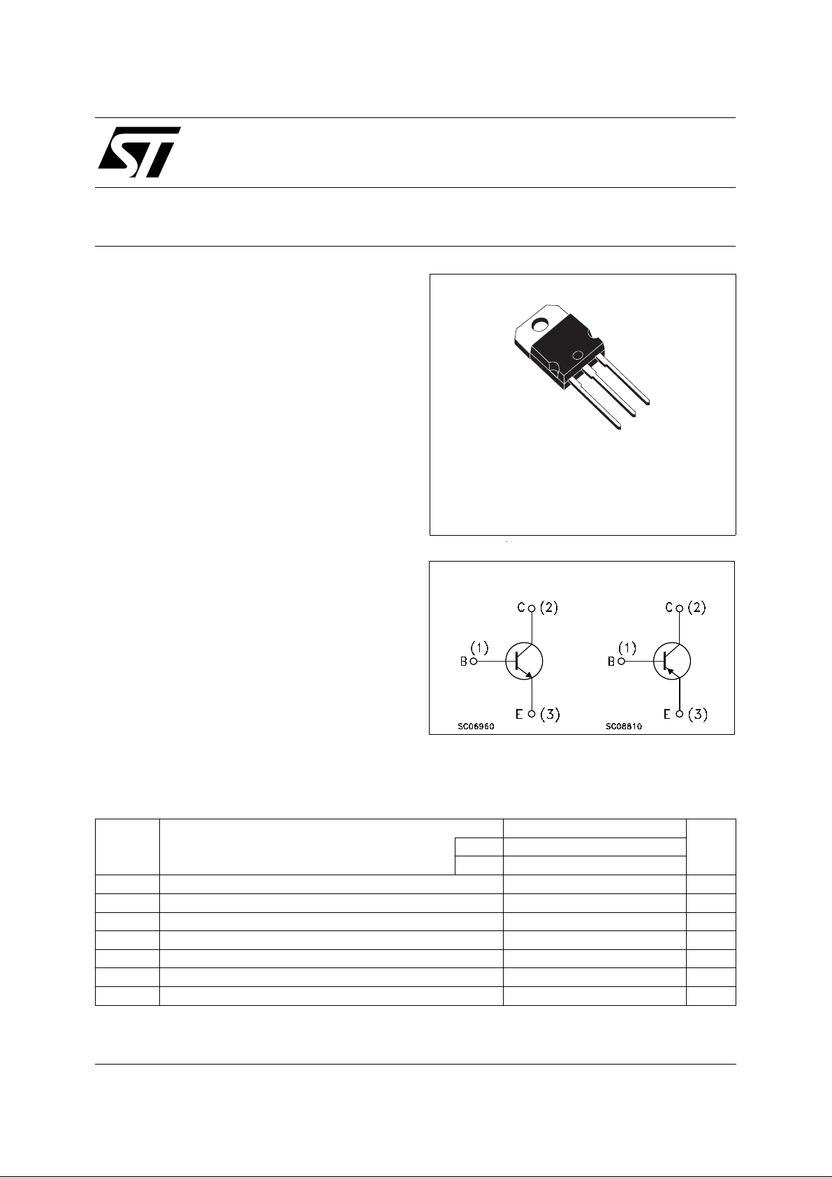
DESCRIPTION
The TIP3055 is a silicon Epitaxial-Base Planar
NPN transistor mountend in TO-218 plastic
package. It is intented for power switching
circuits, series and shunt regulators, output
stages and hi-fi amplifiers.
The complementary PNP type is the TIP2955.
TO-218
3
2
1
INTERNAL SCHEMATIC DIAGRAM
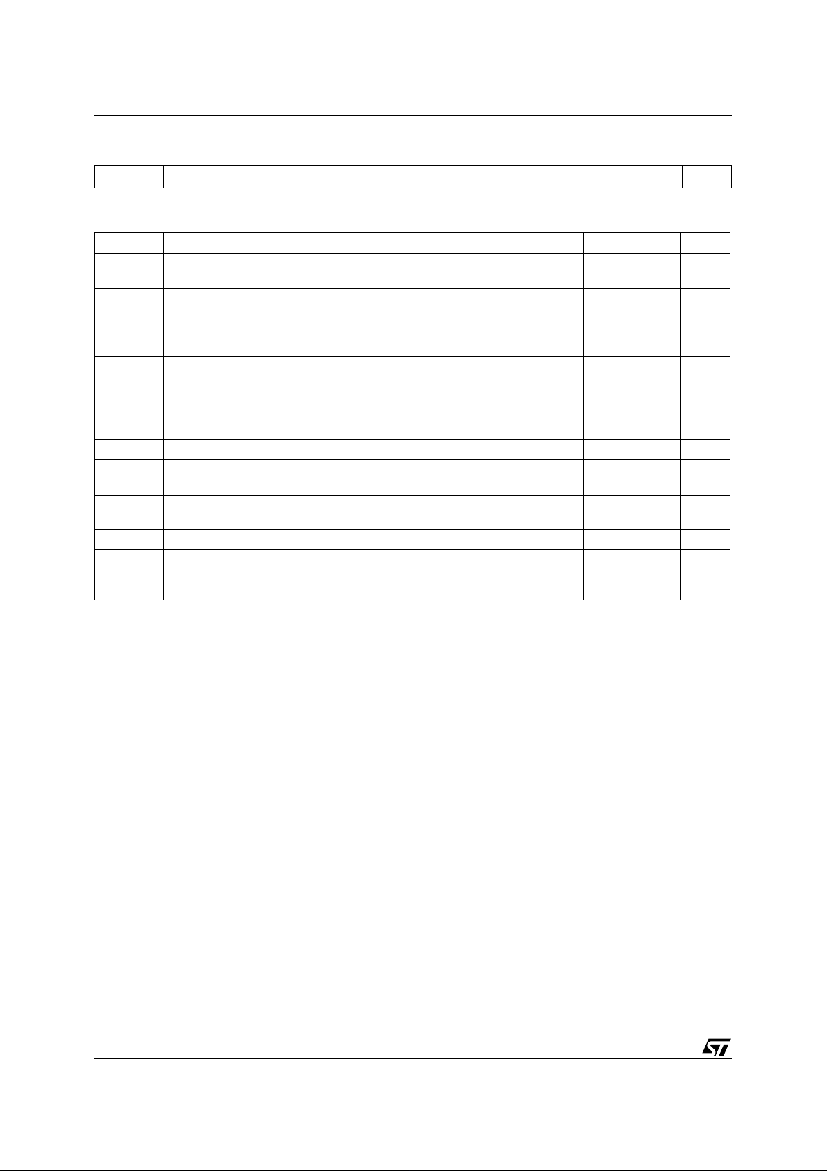
ABSOLUTE MAXIMUM RATINGS
Symbol Parameter Value Unit
PNP TIP2955
NPN TIP3055
V
V
P
T
For PNP types voltage and current are negative.
Collector-Base Voltage (IE = 0) 100 V
CBO
Collector-Emitter Voltage (IB = 0) 60 V
CEO
Collector Current 15 A
I
C
Base Current 7 A
I
B
Total Dissipation at Tc ≤ 25 oC
tot
Storage Temperature -65 to 150
stg
Max. Operating Junction Temperature 150
T
j
90 W
o
C
o
C
August 1999
1/4
TIP2955/TIP3055
THERMAL DATA
R
thj-case
Thermal Resistance Junction-case Max 1.4
o
C/W
ELECTRICAL CHARACTERISTICS
= 25 oC unless otherwise specified)
(T
case
Symbol Parameter Test Conditions Min. Typ. Max. Unit
I
CEX
I
CEO
I
EBO
V
CEO(sus)
Collector Cut-off
Current (V
= -1.5V)
BE
Collector Cut-off
Current (I
= 0)
B
Emitter Cut-off Current
(I
= 0)
C
∗ Collector-Emitter
= 100 V
V
CE
V
= 100 V TJ = 150 oC
CE
= 30 V 0.7 mA
V
CE
= 7 V 5 mA
V
EB
I
= 30 mA 60 V
C
1
5
Sustaining Voltage
(I
= 0)
B
V
∗ Collector-emitter
CE(sat)
Saturation Voltage
V
∗ Base-emitter Voltage I
BE
h
∗ DC Current Gain I
FE
h
Small Signal Current
fe
= 4 A IB = 0.4 A
I
C
I
= 10 A IB = 3.3 A
C
= 4 A VCE = 4 V 1.8 V
C
= 4 A VCE = 4 V
C
I
= 10 A VCE = 4 V
C
20
5
1
3
70
IC = 1 A VCE = 10 V f = 1 KHz 15
Gain
f
t
t
∗
Pulsed: Pulse duration = 300 µs, duty cycle 1.5 %
For PNP type, voltage and current value are negative.
Transition-Frequency IC = 0.5 A VCE = 10 V f = 1 MHz 3 MHz
T
RESISTIVE LOAD
Turn-on Time
on
Turn-off Time
off
IC = 6 A IB1 = - I
= 5 Ω V
R
L
BE(off)
= 0.6 A
B2
= - 4 V
0.5
0.9
mA
mA
V
V
µs
µs
2/4
 Loading...