

SGS Thomson Microelectronics TIP146, TIP140, TIP147, TIP142, TIP145 Datasheet
...
TIP140/141/142
®
COMPLEMENTARY SILICON POWER
■ TIP141, TIP142, TIP145 AND TIP147 ARE
STMicroelectronics PREFERRED
SALESTYPES
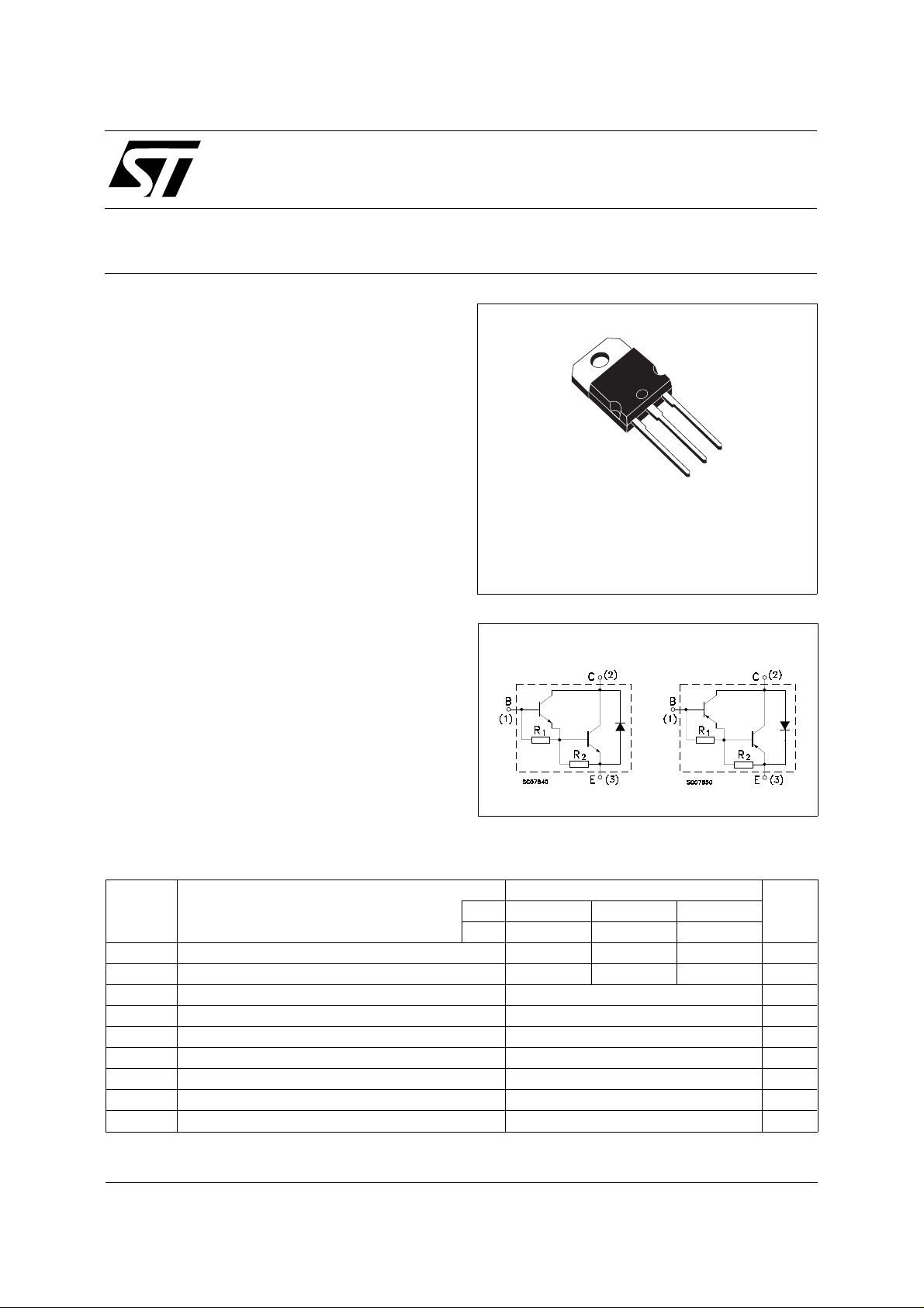
■ COMPLEMENTARY PNP - NPN DEVICES
■ MONOLI THIC D A RLING TO N
CONFIGU R ATIO N
■ INTEGRATED ANTIPARALLEL
COLLECTOR-EMITTER DIODE
APPLICATIONS
■ LINEAR AND SWITCHING INDUSTRIAL
EQUIPMENT
DESCRIPTION
The TIP140, TIP141 and TIP142 are silicon
Epitaxial-Base NPN power transistors in
monolithic Darlington configuration, mounted in
TO-218 plastic package. They are intented for
use in power linear and switching applications.
The complementary PNP types are TIP145,
TIP146 and TIP147 respectively .
TIP145/146/147
DARLINGTON TRANSISTORS
3
2
1
TO-218
INTER NAL SCH E M ATI C DIAG RA M
Typ. = 5 KΩ R2 Typ. = 150 Ω
R
1
ABSOLUTE MAXIMUM RATINGS
Symbol Parameter Value Unit
NPN TIP140 TIP141 TIP142
PNP TIP145 TIP146 TIP147
V
V
V
I
P
T
For PNP types voltage and current values are negative.
March 2000
Collector-Base Voltage (IE = 0) 60 80 100 V
CBO
Collector-Emitter Voltage (IB = 0) 60 80 100 V
CEO
Emitter-Base Voltage (IC = 0) 5 V
EBO
I
Collector Current 10 A
C
Collector Peak Current 20 A
CM
Base Current 0.5 A
I
B
Total Dissipation at T
tot
Storage Temperature -65 to 150
stg
T
Max. Operating Junction Temperature 150
j
≤ 25 oC
case
125 W
o
C
o
C
1/4

TIP140 / TIP141 / TIP142 / TIP14 5 / TIP146 / TIP147
THERMAL DATA
R
thj-case
Thermal Resistance Junction-case Max 1
o
C/W
ELECTRICAL CHARACTERISTICS (T
= 25 oC unless otherwise specified)
case
Symbol Parameter Test Conditions Min. Typ. Max. Unit
I
CBO
Collector Cut-off
Current (I
= 0)
E
for TIP140/145 V
for TIP141/146 V
for TIP142/147 V
I
CEO
Collector Cut-off
Current (I
= 0)
B
for TIP140/145 V
for TIP141/146 V
for TIP142/147 V
I
EBO
V
CEO(sus)
Emitter Cut-off Current
(I
= 0)
C
* Collector-Emitter
Sustaining Voltage
(I
= 0)
B
= 5 V 2 mA
V
EB
I
= 30 mA
C
for TIP140/145
for TIP141/146
for TIP142/147
V
For PNP types voltage and current values are negative.
∗ Pulsed: Pulse duration = 300 µs, duty cycle 1.5 %
* Collector-Emitter
CE(sat)
Saturation Voltage
V
* Base-Emitter Voltage IC = 10 A VCE = 4 V 3 V
BE(on)
h
* DC Current Gain IC = 5 A VCE = 4 V
FE
RESISTIVE LOAD
t
t
on
off
Turn-on Time
Turn-off Time
IC = 5 A IB = 10 mA
I
= 10 A IB = 40 mA
C
I
= 10 A VCE = 4 V
C
IC = 10 A IB1 = 40 mA
= -40 mA RL = 3 Ω
I
B2
= 60 V
CB
= 80 V
CB
= 100 V
CB
= 30 V
CE
= 40 V
CE
= 50 V
CE
60
80
100
1000
500
0.9
4
1
1
1
2
2
2
2
3
mA
mA
mA
mA
mA
mA
V
V
V
V
V
µs
µs
2/4
 Loading...