

SGS Thomson Microelectronics THDT58S, THDT58S1 Datasheet

THDT58S1
THDT58S
ApplicationSpecific Discretes
A.S.D.
FEATURES
CROWBARPROTECTION
DUALASYMMETRICALTRANSIENT
SUPPRESSOR
PEAKPULSE CURRENT:
= 75 A, 10/1000µs for THDT58S.
-I
PP
= 35 A, 10/1000µs for THDT58S1.
-I
PP
HOLDINGCURRENT= 150 mAmin
BREAKDOWNVOLTAGE= 58 V.
BREAKOVERVOLTAGE= 80Vmax
DESCRIPTION
This device has been especially designed to
protect subscriber line card interfaces (SLIC)
againsttransientovervoltages.
Its ion-implanted technology confers its excellent
electricalcharacteristics.
This is why this device easily fulfils the main
protection standards which are related to the
overvoltagessuppressionon telecomlines.
The product pinout is compatiblewith TO202 and
TO220packages.
TRANSIENT VOLTAGE SUPPRESSOR
FOR SLIC PROTECTION
SIP3
SCHEMATIC DIAGRAM
NC
Tip
1
2
COMPLIESWITHTHEFOLLOWINGSTANDARDS:
CCITTK20:
VDE0433 : 10/700µs 2kV
VDE0878 : 1.2/50
CNETI3124: 0.5/700µs 1kV
BELLCORE
TR-NWT-001089:
(*)withseries resistors orPTC.
TM: ASD is trademarks of SGS-THOMSON Microelectronics.
February 1998 - Ed: 3
10/700µs 1kV
5/310µs 25A
µs 45/50A(*)
5/200
µs 1.5kV
1/20 µs 40A
0.2/310µs 25A
10/1000µs 1kV
10/1000µs 35/75A(*)
GND
Ring
3
4
1/7

THDT58S / THDT58S1
ABSOLUTE MAXIMUMRATINGS
(T
amb
=25°C)
Symbol Parameter THDT58S1 THDT58S Unit
I
I
TSM
PP
Peak pulsecurrent (seenote 1)
Non repetitivesurgepeak on-state
10/1000µs
8/20 µs
2/10 µs
35
70
80
75
150
t = 20 ms 20 30 A
current (F = 50Hz)
dV/dt Criticalrate of rise of off-state
67%V
BR
5 kV/µs
voltage
T
stg
T
j
T
L
Storagetemperaturerange
Maximumoperatingjunctiontemperature
Maximumleadtemperaturefor soldering
-55 to +150
+150
-40to+150
+150
260 260 °C
during 10s
Note 1 : Pulsewaveform :
10/1000µstr=10µst
5/310µst
2/10µst
=1000µs
=5µst
r
=2µst
r
p
=310µs
p
=10µs
p
100
50
%I
PP
A
°C
°C
0
t
t
rp
THERMAL RESISTANCES
Symbol Parameter Value Unit
(j-a)
R
th
Junctionto ambient
80 °C/W
t
2/7
THDT58S / THDT58S1
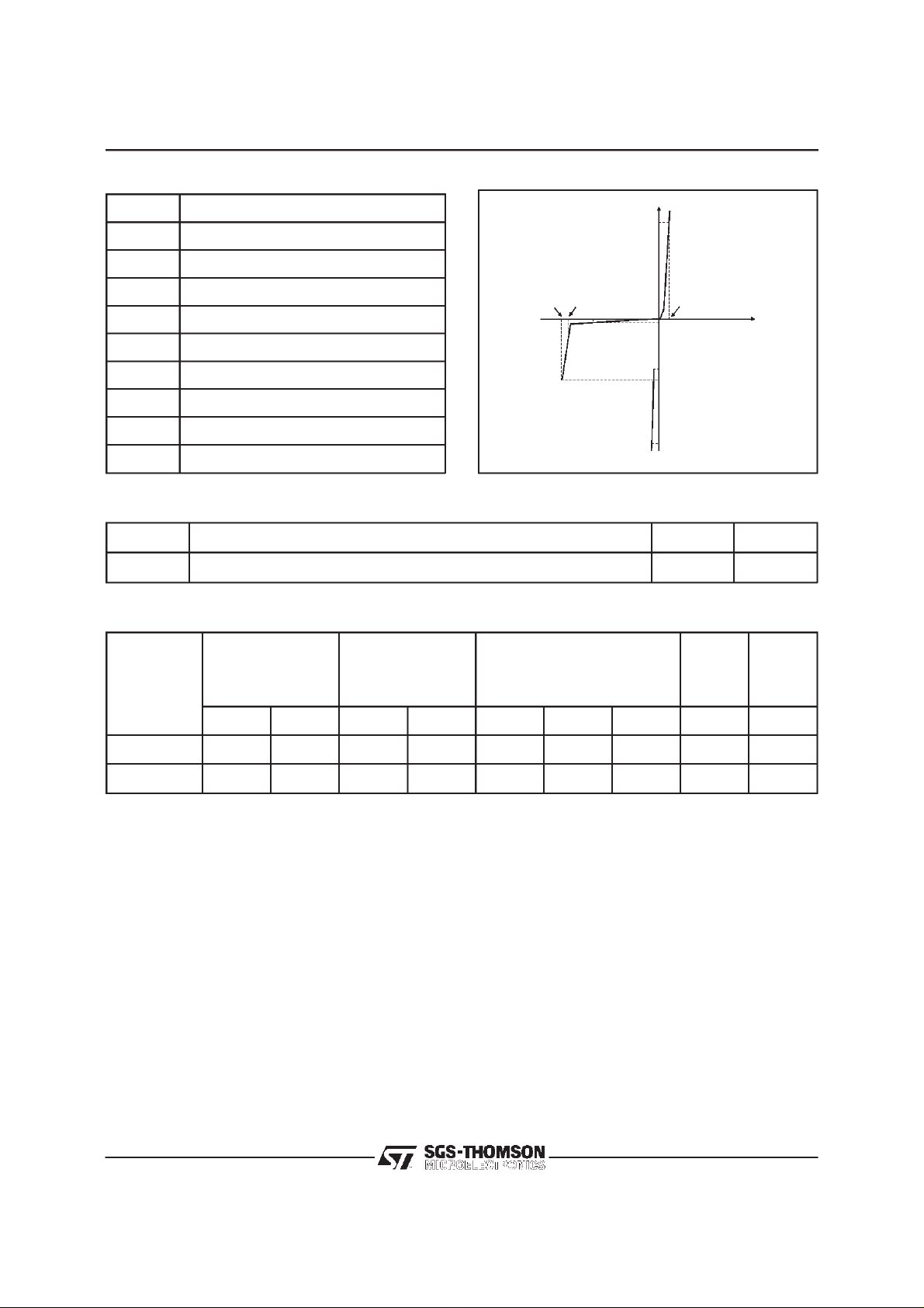
ELECTRICAL CHARACTERISTICS
Symbol Parameter
V
RM
I
RM
V
BR
V
BO
I
H
V
I
BO
I
PP
C
Stand-offvoltage
Leakagecurrentat V
Breakdownvoltage
Breakovervoltage
Holdingcurrent
ForwardVoltagedrop
F
Breakovercurrent
Peakpulse current
Capacitance
RM
(T
amb
=25°C)
VBO
VBR
VRM
I
F
I
VF
IRM
IH
IBO
pp
I
V
1 - PARAMETERRELATEDTO THE DIODE LINE/GND
Symbol Testconditions Value Unit
V
IF=5 A tp = 500 µs5V
F
2 - PARAMETERSRELATEDTO THE PROTECTIONTHYRISTOR
Type I
max. min. max. min.
@V
RM
A V V mA V mA mA mA pF
µ
RM
VBR@I
R
VBO@I
note1
BO
max.
I
H
min.
note2
max.
note3
THDT58S 10 56 58 1 80 150 800 150 400
THDT58S1 10 56 58 1 80 50 800 150 200
Note 1 : See thereferencetest circuit 1 for IBOand VBOparameters.
Note 2 : See testcircuit2.
Note 3 : V
= 1V, F= 1MHz.
R
C
3/7
 Loading...