

SGS Thomson Microelectronics TEA7532FP, TEA7532DP Datasheet
.PROGRAMMABLEGAININ STEPSOF6 dB
.ON/OFFPOSITION
.LOWVOLTAGE
.POWER: 100 mWAT 5 V
DESCRIP TION
This16 pinsIC is designedfor monitor
(loudspeaker)telephoneset andprovides:
a) Signalamplificationformonitoring(loudspeaker)
b) Antiacousticfeedback(antilarsen)
c)Antidistortionbyautomaticgainadaptation
d) Antilarsenadjustment(full duplex)
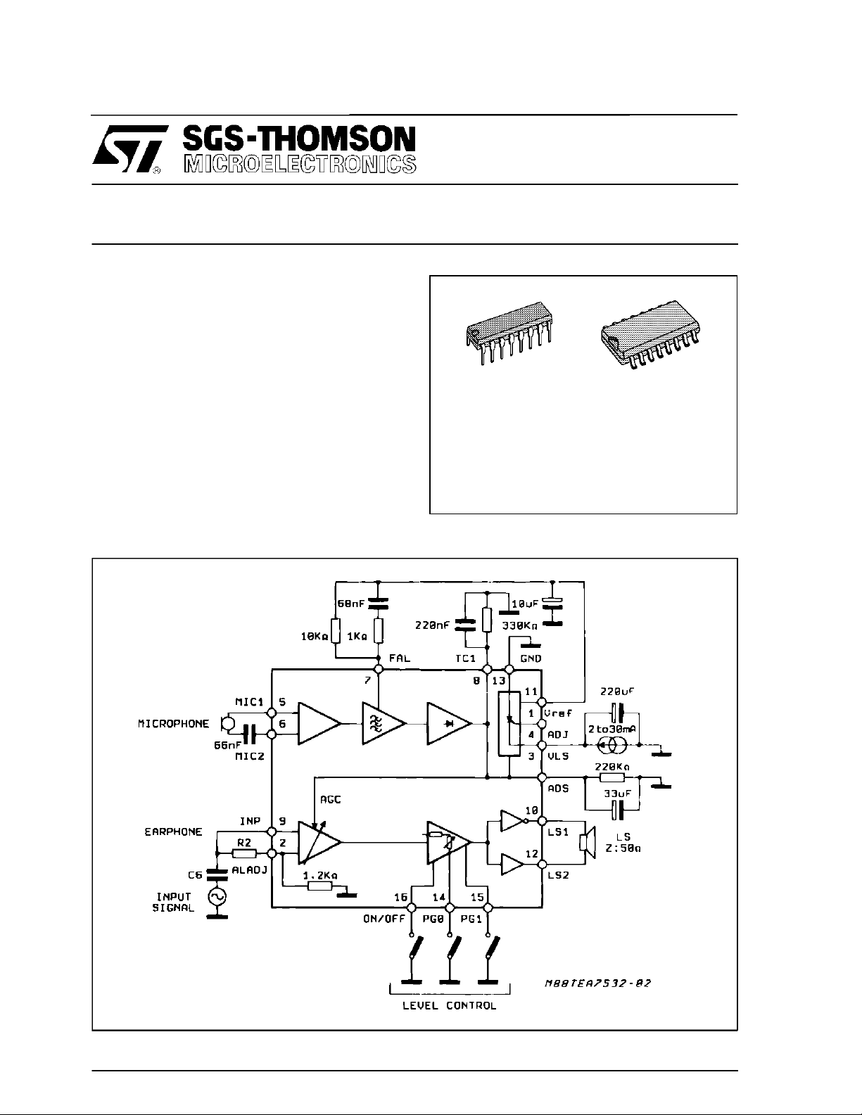
BLOCK DI AG RAM
TEA7532
MONITOR AMPLIFIER
DIP 16
ORDERING NUMBERS : TEA7532DP(DIP16)
SO16
TEA7532FP(SO16)
July1993
1/16
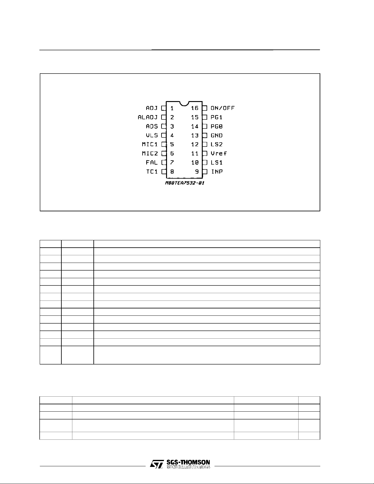
TEA7532
PIN CONNECTI O N (Top view)
PIN DESCRIPTION
N° Symbol Description
1 ADJ Adjust Internal Reference V
LS
2 ALADJ Antilarsen Adjustement
3 ADS Antidistortion
4V
LS
Supply
5 MIC1 Microphone Input
6 MIC2 Microphone input
7 FAL Antilarsen Filter
8 TC1 Antilarsen Time Constant
9 INP Input Signal
10 LS1 Output Loudspeaker 1
11 V
REF
Internal Resistance
12 LS2 Output Loudspeaker 2
13 GND Ground
14
15
16
PG0
PG1
ON/OFF
Inputs Program Level to Loudspeaker
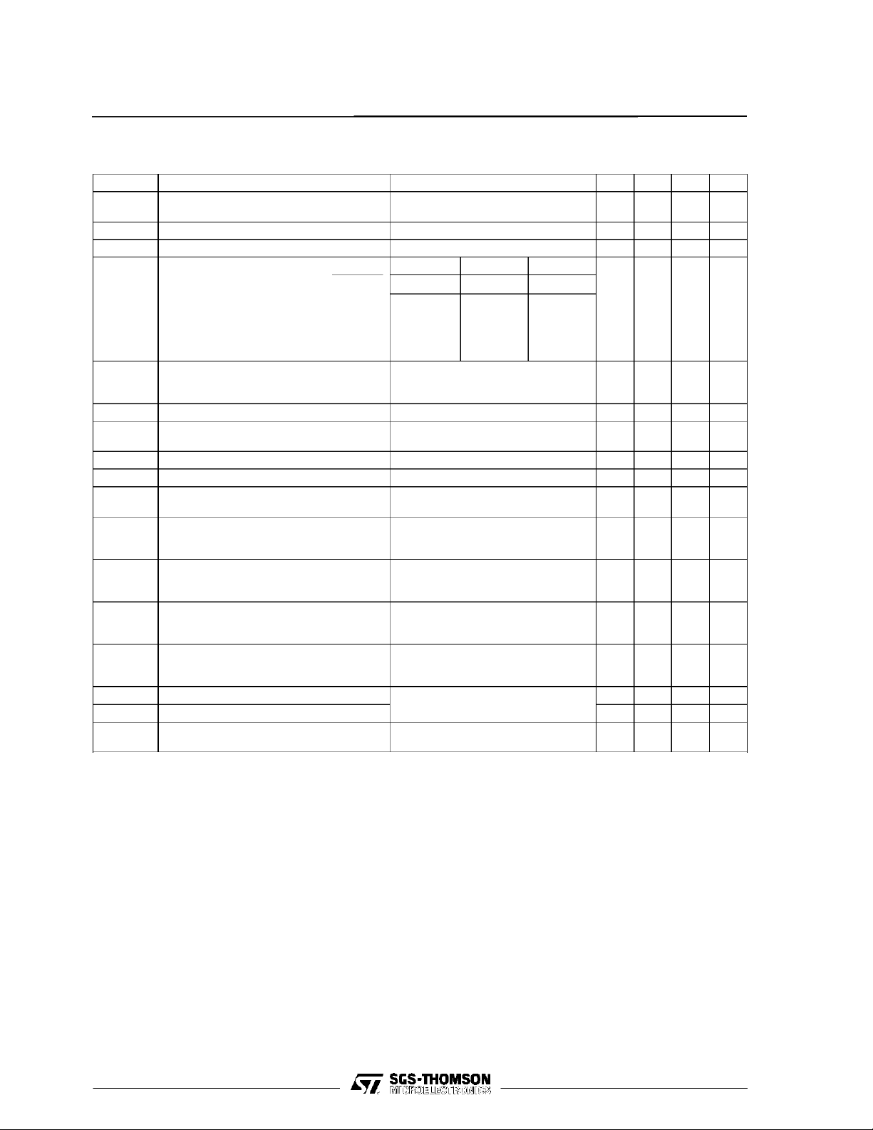
ABSOLUTE MAXIMUM RATINGS
Symbol Parameter Value Unit
T
op
V
LS
I
LS
V
Temperature Range –5 to + 45 °C
Supply Voltage 6 V
Supply Current for T > 300ms
for T ≤ 300ms
Voltage Level (pins, PG0, PG1, on/off) 0.6 > to VS+ 0.6 V
L
90
150
mA
mA
2/16
TEA7532
ELECTRICAL CHARACTERISTICS (T
=25oC, ILS= 30mA unless otherwisespecified)
amb
Symbol Parameter Test Conditions Min. Typ. Max. Unit
V
LS1
V
LSM
V
ADJ
G
G000
G001
G010
G011
G100
VLSSupply ILS= 2mA (fig. 7)
= 30mA (fig. 7)
I
LS
VLSMaximum I
=50µA (fig. 7 ; So = closed) 5.5 V
pin 1
Voltage Pin 1 ILS= 2mA to 30mA (fig. 7) 1.1 1.25 1.4 V
V
− V
10
Loudspeaker Amplifier Gain =
12
V
ON/OFF PG0 PG1
9
GND
GND
GND
GND
V
LS
GND
GND
V
LS
V
LS
X
GND
V
LS
GND
V
LS
X
2.6 3.0
12
18
24
30
THD Distortion f = 300Hz to 2kHz,
V
10–V12
G = G011, (fig. 8)
G2 [V(10) – V(12)]/V2 P
Z
MICIN
Z
INPIN
Z
V
OFFS
I
ON/OFF
I
PG0
I
PG1
I
ON/OFF
I
PG0
I
PG1
V
IL ON/OFF
V
IL PG0
V
IL PG1
V
IH ON/OFF
V
IH PG0
V
IH PG1
G
Microphone Input Symetrical at (pins 5-6)
Earphone Input (fig. 9) 2.2 2.8 3.4 kΩ
Antilarsen Adjustment Input 1 1.2 1.45 kΩ
IN2
Ouput Offset
[V
(10)–V(12)
]
Input Current ON State V
Input Current OFF State V
Input Voltage ON State 0.45
Input Voltage OFF State 1.5
Microphone Gain = V
MIC
(7)
/[V
(5)–V(6)
]
Vg Voltage Pin 8 0.48 0.67 0.75 V
G
Loudspeaker Attenuated
ATT
Gain = [V
(10)–V(12)
]/V
(9)
G0=PG1=VLS,V8
Asymetrical at (pin 6) fig. 9
G011 ; (fig. 8) – 50 50 mV
PG1
PG1=VLS
V
MIC
G011 ; V8= 0.6V ; (fig. 10)
G011 ; V
= 0.8V
= 0V ; (fig. 8) – 10
; (fig.8) 1
= 10mV
= 0.4V ; (fig. 10) 20
8
,
RMS
= 0.8V (fig. 8) 30 32 34 dB
–10
–10
1.5
1.5
, f = 2kHz (fig. 10)
RMS
22.5 23.5 24.5 dB
3.4
3.15
3.4VV
14
16
20
22
26
28
32
–30
34
–20
2%
4.5 kΩ
–5
–5
–5
1
1
0.45
0.45
–3030–20 dB
dB
dB
dB
dB
dB
µA
µA
µA
µA
µA
µA
V
V
V
V
V
V
dB
FUNCTIO NAL DESCRIPTI ON
TEA7532performs the followingfunctions:
Thecircuitamplifiesthe incomingsignaland feeds
itto the loudspeaker.PG0andPG1 inputsare used
to set the loudspeakergain in a range of 32dB to
14dBin 6dB steps.
The TEA7532inputs (PG0, PG1, ON/OFF) permit
the loudspeakertobe cut-offthus ensuringprivacy
of communication.
- The antilarsen (antiacousticfeedback)system is
incorporated.
- The maximum power available on a 50Ω impedanceloudspeakeris25mWat3 volts and 100mW
at 5V.
Limitvaluesfor externalcomponents:
R3 min = 5 kΩ (R3 adjustVLS),R7 max= 390 kΩ,
R6 min = R7/35
Rmaxbetweenpin5 and6=10kΩ+C min= 10nF.
3/16

TEA7532
Figure 1 : LoudspeakerGain VersusVoltage on
Pin(3) - (8) with Pin2 Open.
(*) ATTENUATION =
Zin2(1.2 K) R2=10K⇒ATT = 20 dB
Zin2(1.2 K) + R2(EX T) R2=3 K⇒ATT ≈ 10 dB
Figure 3 : ACOutput VoltageVersusAmplifier
Gain.
Figure2 :LoudspeakerGain VersusVoltageon
Pin(3) - (8)and VersusR
.(*)
2
Figure4 : Power Availableon Loudspeaker
VersusV
Typical Curve.
LS
Figure 5 : DistortionVersus Output Power. Figure6 : OutputPowerVersusSupplyCurrent.
4/16
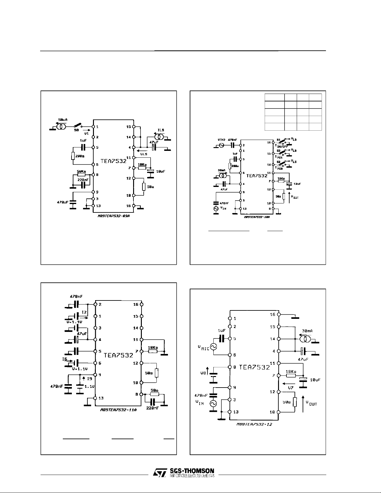
TEST CIRCUI TS
Figure 7 : ShuntvoltageRegulator/Reference
Voltageat Pin 1.
TEA7532
Figure8 : LoudspeakerAmplifier :Gain/Distor
tion/OutputOffset.
S1 S2 S3
G1XX 1 X X
G000 0 0 0
G010 0 1 0
G001 0 0 1
Note : S0 open for VLS 1
S0 close for VLSM.
Figure 9 : ImpedanceZMIC, ZINP andZin2.
V (10)– V (12) V
• G= =
• VOFFS with Vin = 0.
V
LS
G
ND
V (9) V (9)
=1
=0
out
Figure10 : AntiacousticFeedbackSystem at
G011.
Zmic = ; Zinp = ; Zin2 =
1.1V 1.1V 1.1V
I6 I9 I2
5/16
 Loading...