

TEA7092
TELEPHONE ANALOG FRONTEND
SPEECH
.
DC LINE CURREN T RANGE FROM 6 TO120mA
.
EXTERNALLYADJUSTABLE:
- Tx ANDRxGAIN
- MAXIMUMTRANSMIT LEVEL
- RETURN LOSS
- SIDETONENETWORKS
- Tx ANDRxAGC(LINECURRENT STARTUP
VALUE ANDSLOPE)
.
SOFTCLIPPINGONTxCHANNEL
.
SQUELCH ON Tx CHANN ELT O REDUCE NOISE
ENVIRONMENT AND TO IMPROVE HOWLING
IMMUNITYIN LOUDHEARIN GMODE
.
RECEIVING AMPLIFIER FOR PIEZO AND
ELECTRODYNAMICTRANSDUCERS
.
FREQUENCY GENERATOR FOR WAITING
MELODY
.
ERRORBEEP GENERATOR
.
HOLD LINE CURRENT DETECTOR FOR
TRANSFER/AUTORELEASEFEATURE
.
PROGRAMMABLE BY MICROCONTROLLER
SERIALBUS:
- -6dBON Tx CHANNEL
- +6dBONRx CHANNEL
- AGCINHIBITION ONTx ANDRxCHANNELS
FORPABX USE
- SQUELCHINHIBITION
GROUPLISTENING / ONHOOK DIALING
.
ANTI-HOWLING WITH ACOUSTIC FEEDBACKSYSTEMCOUPLEDTOSQUELCH
.
RING MELODY CONTROL AND ERROR
BEEPGENERATORS
.
PROGRAMMABLE BY MICROCONTROLLER
SERIALBUS:
- DIGITALVOLUME CONTROL (7 STEPS OF
4dB EACH) AND OFF MODE
.
PROGRAMMABLE BY MICROCONTROLLER
SERIALBUS:
- DIGITALVOLUME CONTROL(15STEPSOF
4dB EACH) AND OFF MODE
- RING FREQUENCY GENERATOR (MORE
THAN200 FREQUENCIES AVAILABLE)
DIALING
.
PROGRAMMABLE BY MICROCONTROLLER
SERIALBUS:
- DTMF GENERATOR
- 2V DC LINE VOLTAGE DURING THE MAKE
PERIODIN PULSEMODE
MICROCONTROLLER INTERFACE
.
3.5V STABILIZEDSUPPLY
.
TWO WIRESSERIAL BUS INTERFACE
.
RINGINDICATOR
.
PON LINE CURRENTINDICATOR
.
RESETSIGNAL
.
LINE CURRENT VARIATION INDICATOR
(FOR TRANSFERFEATURE)
.
OSCILLATORWITH STANDBY MODE
CORDLESS AND ANSWERING MACHINE
INTERFACE
.
SELF BIASED LOUDSPEAKER AMPLIFIER
AND MICROCONTROLLER INTERFACE FOR
ANSWERING MACHINE
.
SIGNAL INPUT AND OUTPUT INTERFACE
FOR CORDLESS
.
V
SUPPLYCANBE EXTERNALLYFORCED
RMC
TO 5V FOR EASY INTERFACE WITH A MAIN
POWEREDMICROCONTROLLER
HANDFREE INTERFACE
.
PINS AND SOFTWARE FACILITY FOR EASY
INTERCONNECTION WITH HANDSFREE
CONTROLLER I.C. LIKE TEA7540
RING ON LOUDSPEAKER
.
EMBEDDED SWITCH MODE POWER SUPPLY DRIVER TO FEED THE LOUDSPEAKER
AMPLIFIERDURINGRING MODE
July 1996
TQFP44
(Plastic Quad Flat Package)
ORDER CODES : TEA7092TQ - TEA7092TQT
1/24
TEA7092
DESCRIPTION
The TEA7092is a TelephonesetAnalogFrontEnd
(TAFE) interface intended for use in conjunction
with amicrocontroller.
In thisconfigurationthe TEA7092providesaworldwide telephone set with loudhearing and melody
ringer onloudspeaker.An handsfreetelephoneset
can be built by adding the TEA7540 handsfree
controller.
The simpleinterfacewitha+5Vmainsupplyallows
to use the TEA7092 in terminal like Answering
machine,FAX and cordlessbase station.
Repertory dialer (memory on MCU) and various
features (HOLD, Tone/Pulse,Flash, Mute, adjustable Ringer and Loudspeaker levels...) are programmable by the MCU through the serial bus
interface.
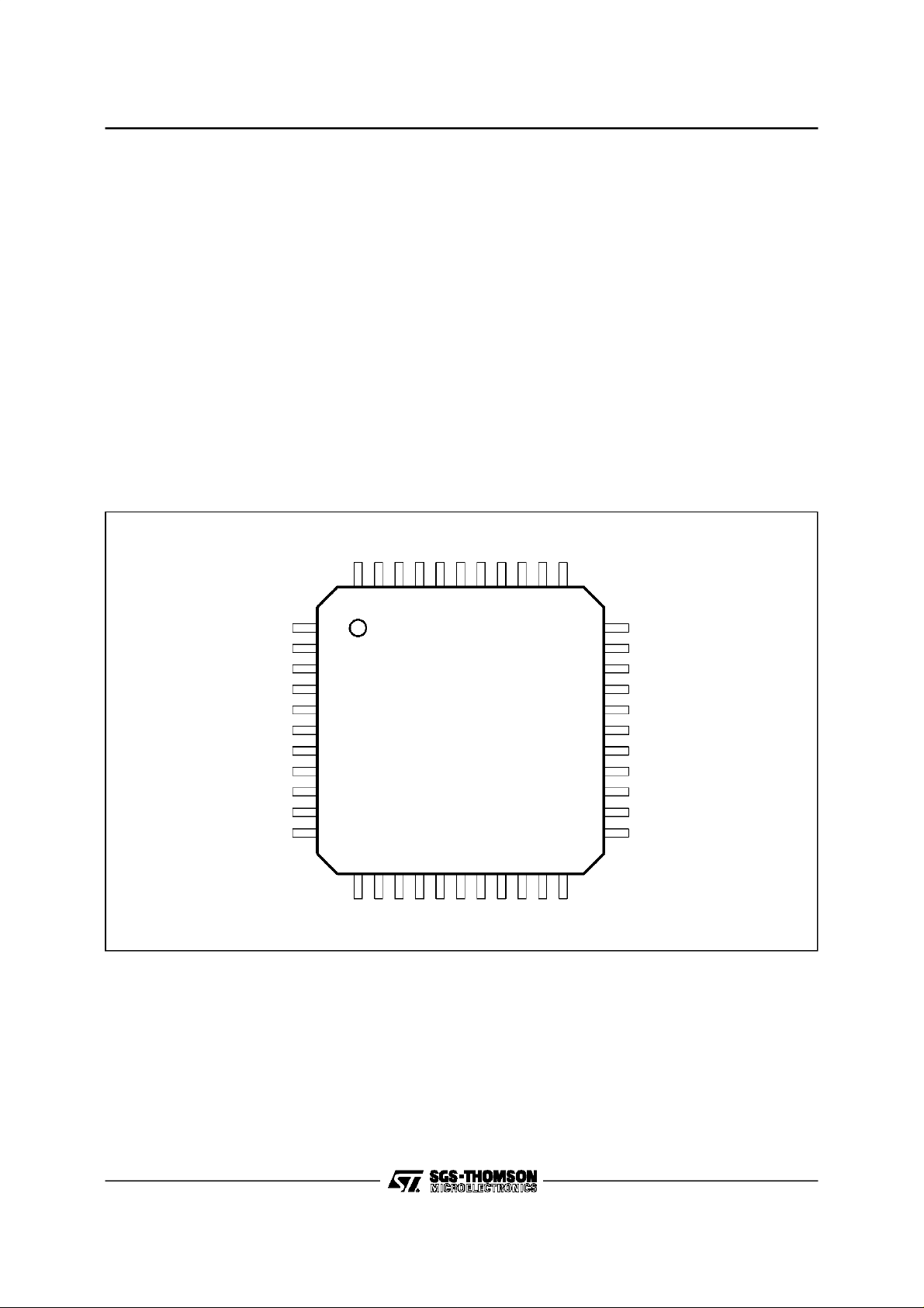
PIN CONNECTIONS
DTMF2
GNDP
RCO
V
V
VL
V
REFL
LSIN
LSSOF
DTMF1
V
RMC
OSC
RI/VI
RESET
LSOUT
4443424140393837363534
1
LS
2
MC
3
4
5
6
7
8
9
10
11
1213141516171819202122
The MCU throughthe serial bus interface.
The concept using TAFE and Microcontroller is
calledBICHIPapproach.
BENEFITS
The benefits of this concept are :
- Saving of externalcomponents.
- Easy upgrade of the features (memories, LCD
driver,Answeringmachine, FAX, Cordless ...).
- Replacement of configuration switches
(PABX/Public, Tone/Pulse) and potentiometers
for loudspeakerand ringer control, by EEPROM
settings.
- Reliability and cost improvements.
RSU
SWP
VZP
GREC
EAR-
EAR+
ISL
33
32
31
30
29
28
27
26
25
24
23
ILL
AGND
SLP
VS
I
REF
SOFTL
TSOFT
V
CC
V
REF
MIC2
MIC1
2/24
PON
CLK
DATA
SNSL
SNLL
ASQ
ASC
RECIN
REOUT
GTR
HFIN
7092-01.EPS
PIN DESCRIPTION
Pin Number Name Description
1V
2V
LS
MC
3 VL Transmit Output
4V
REFL
5 LSIN Loudspeaker Amplifier Input
6 LSSOF Loudspeaker Softclipping Time Constant
7 DTMF1 DTMF Filter 1
8V
RMC
9 OSC Oscillator Input
10 RI/VI Ring Indicator / Line Current Variation Indicator
11 RESET Microcontroller Reset Output
12 PON Line Current Indicator Output
13 CLK Serial Bus Clock Input
14 DATA Serial Bus Data Input
15 SNSL Short Line Sidetone Network Input
16 SNLL Long Line Sidetone Network Input
17 ASQ Antiacoustic & Squelch Time Constant
18 ASC DC Offset Cancellation of Squelch Amplifier
19 RECIN Receive Input
20 REOUT Receive Outputfor Handsfree Interface & Loudspeaker Input
21 GTR Transmit Gain Adjustment
22 HFIN Handsfree Microphone Input Referenced to V
23 MIC1 Microphone Input 1 Referenced to V
24 MIC2 Microphone Input 2 Referenced to V
25 V
26 V
REF
CC
27 TSOFT Transmit Softclipping Time Constant
28 SOFTL Softclipping Adjustment
29 I
REF
30 VS Active Self Inductor & DC Characteristic Adjustment
31 SLP DC Mask Slope Adjustment
32 AGND Analog Ground & Negative Line Voltage
33 ILL Long Line Speech Control Adjustment (GMAX)
34 ISL Short Line Speech Control Adjustment (GMAX-6dB)
35 EAR+ Earphone Output
36 EAR- Earphone Output
37 GREC Receive GainAdjustment
38 VZP Switch Mode Power Supply Internal Zener
39 SWP Switch Mode Power Supply Output Switch
40 RSU Ring Start-up Level
41 RCO Ring Power Output Control
42 DTMF2 DTMF Filter 2
43 GND Power Ground & Negative Line Voltage
44 LSOUT Loudspeaker Output
Loudspeaker Power Supply
Unregulated Input of Microcontroller Power Supply
Loudspeaker Reference Voltage (VLS/2)
Stabilized Microcontroller Power Supply
REF
REF
Speech Reference Voltage (VCC/2)
Speech Power Supply
Resistor to Set Reference Current
TEA7092
REF
7092-01.TBL
3/24

TEA7092
BLOCK DIAGRAM
REFL
GND 0V
V
LSSOF
LS
V
LS
V
CC
V
TEA7092
13 4615 161926 30
VLS/2
CTRL
LOGIC
HOLD
ILdc 82.ILac I(vls)
STATUS
I LINE SENSING
ILdc
&OUT TX
LOUDSPEAKER
CURRENT SUPPLY
ILac+dc
DC BIAS
AGC
Gmax-Gtl
A
100
INPUTS
LSOUT
SAT
DETECT
DIGITAL
MUX
44
VOLUME
CONTROL
7 steps 4dB
AGC
+RING
LOUDSPEAKER
GND 0V
POWER
LOUDHEARING
Gtl -10 -15 -20 -25dB
VLS
VZP
38
POWER
RCO
41
RING SIGNAL
OUTPUT POWER
(3mA)
CURRENT
EXTRACTOR
GND 0V
RSU
40
POWER
SWITCH MODE
RING
OPTIMISATION
RING
INDICATOR
DC
SERIAL
REGULATOR
ILdc ILac+dc
SWP
39
SUPPLY
CONTROL
ILdc
PON &
GND 0V
RESET
CONTROL
OSCILLATOR
LOGIC CONTROL
RING
MELODY
GENERATOR
LOGIC
SERIAL INTERFACE
MICROCONTROLLER
MUTE
LS
V
GND 0V
3.58MHz
9
14 13 10111282
RMC
V
PON RESET DATA CLK RI/VI OSC
RMC
V
MC
V
4/24
Zasl
LINE
Zall
VS RECINVL SNSL SNLL
CC
V
ILdc
VCC/2
25
REFIREF
V
ILdc
DC
CARACTERISTIC
I&V
REFERENCES
29
31
SLP
LSIN
5
MIXER
SIDETONE
AGC
20
37
GREC
REOUT
AGC CONTROL
MUTE
VERSUS
LINECURRENT
VREF
36
EAR-
RX & TX
-1
EARPHONE
AMPLIFIER
35
EAR+
EARPHO NE
17
ASQ
ASC
dc cut
VL
18
SOFTL
Tx. AMP
MUTE & DTMF
G=200
SQUELCH
ANTI-HOWLING
SOFTCLIPPING
272824
MIC2
TSOFT
1/RGT
AGC
A=10
23
MIC1
MICRO
HAND-FREE
22
HFIN
C21
21
GTR
333432
ILL
RGT
BEEP
VREF
DTMF
I-DACLF I-DACHF
ISL
AGND
SINE CODE
43
GND
742
DTMF1 DTMF2
GND 0V
7092-02.EPS
TEA7092
ABSOLUTEMAXIMUM RATINGS
Symbol Parameter Value Unit
V
RECIN
V
L
I
L
V
RSU
V
SWP
V
VLS
V
VCC
V
VM
V
VRMC
V
PON
V
CLOCK
V
DATA
V
RI/VI
T
oper
T
T
stg
Note: Typical Thermal resistance TQFP44 Copper lead frame70° K/W @ 1W.
Supply Voltage 13 V
Line Voltage 13 V
Line Current 0.15 A
Ring InputVoltage 22 V
Output SwitchVoltage 7 V
Loudspeaker Part Supply 5.5 V
Speech PartSupply Voltage 10 V
Unregulated Microprocessor Supply Voltage 5.5 V
Regulated Microprocessor Supply Voltage 5.5 V
Power-On Out Voltage V
Clock In Voltage V
Data In Voltage V
RI/VI Out Voltage V
+0.3V, GND-0.3V V
RMC
+0.3V, GND-0.3V V
RMC
+0.3V, GND-0.3V V
RMC
+0.3V, GND-0.3V V
RMC
Operating Temperature -20, +70 °C
Junction Temperature -20, +150 °C
j
Storage Temperature -55, +150 °C
7092-02.TBL
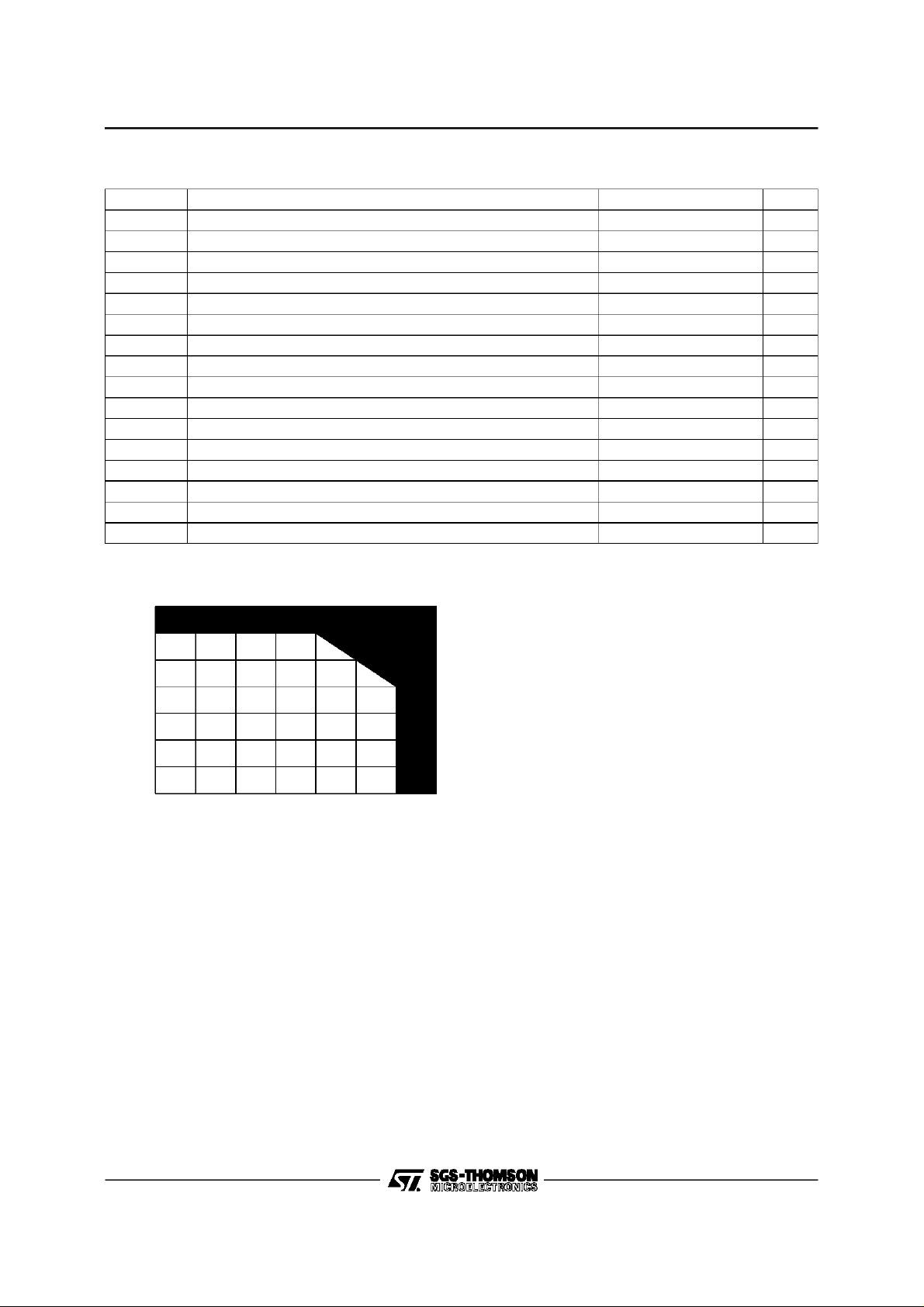
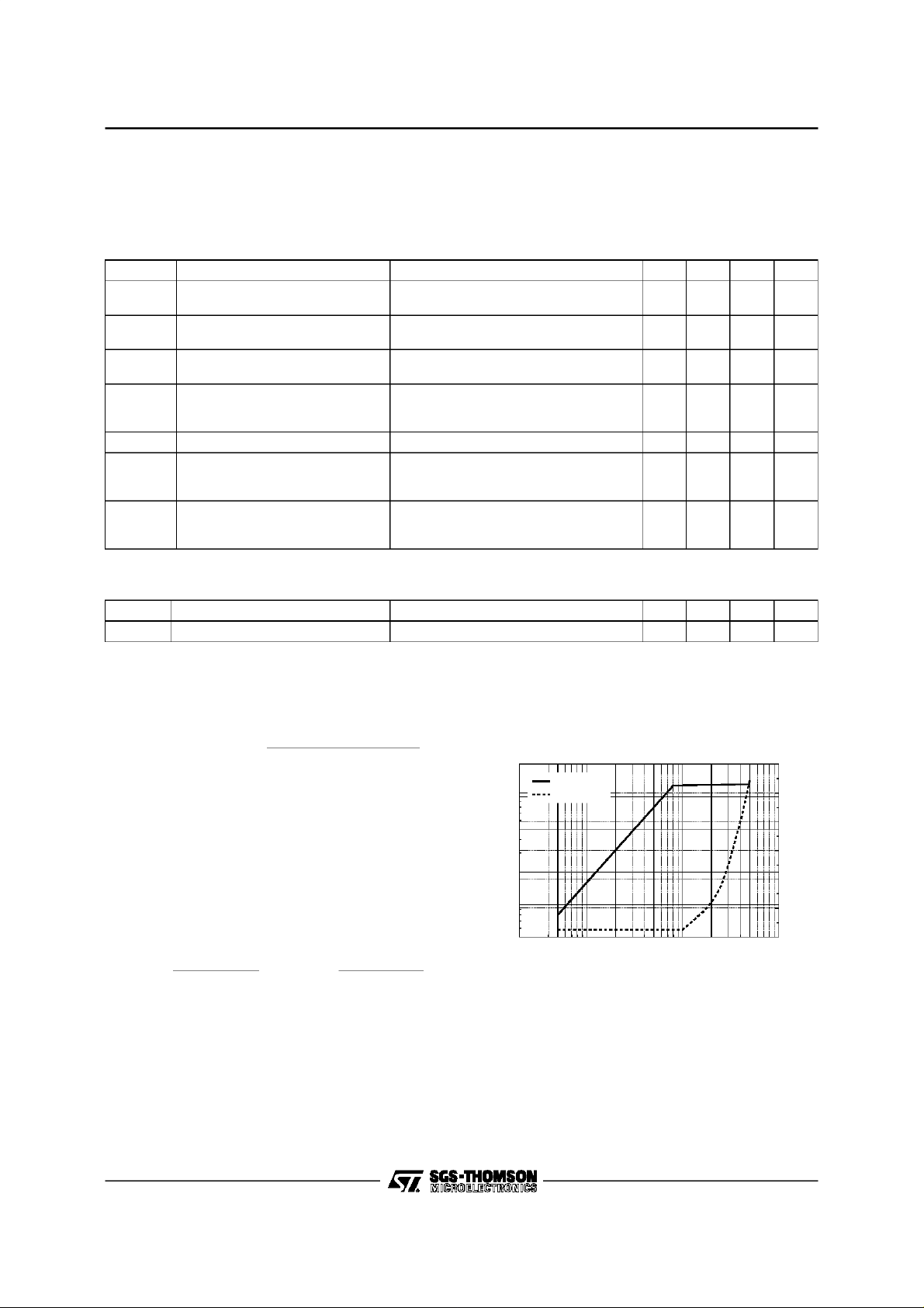
Figure 1 : SafeArea
140
120
100
80
(mA)
L
60
I
40
20
0
02468101214
VL(V)
7092-03.EPS
5/24
TEA7092
DC CHARACTERISTICS (T
BetweenI
) =RS x (40E-6+0.5E-3xIL) +RSLP/55 x (IL- 5.6E-3).
V
L(IL
=8mA and IL= 20mAthe DC slopeis fixed by RS and RSLP :
L
For linecurrenthigherthan20mAthe slopeis fixed by RSLP: V
=25°C,see Test 1)
amb
)=VL(20E-3)+ RSLP/55x(IL- 20E-3).
L(IL
Symbol Parameter Test Conditions Min. Typ. Max. Unit
4.1
4.7
V
V
I
LSQ
Line Voltagein Speech Mode IL= 20mA
L1
Line Voltageafter Having Sent
L2
0010101 Mask Code
Loudspeaker Amplifier Quiescent
Bias Current
Unstabilized Supply :
I(VMC)1
I(V
MC
V
RMC
(V
L-VLS
(V
L-VLS
I
LS1
- Startup Current
)2
- UnregulatedInput Current
Stabilized Microprocessor Supply IL= 20mA, I(V
DropVoltage V
I
LS
)1
)2
Loudspeaker CurrentSupply VLS=2V
RETURN LOSS (T
=25°C,see Test 2
amb
= 90mA
I
L
6.6
IL= 20mA 1.6 2.5 V
VLS= 4.5V 1.1 2.2 mA
= 20 mA, VLSno connect, VMC= 2.4V
I
L
V
RMC
V
RMC
LAC
IL= 20mA
I
L
I
L
I
L
= 2.4V
= 3.75V
=0V
RMS
= 90mA
= 20mA
= 90mA
) = -1.8or 0mA 3.2 3.5 3.75 V
RMC
10215
117013
5.25
7.5
8.4VV
2.7 3.6mAmA
1.1
1.3
1.8
2.3VV
77
Symbol Parameter Test Conditions Min. Typ. Max. Unit
RLoss Return Loss I
= 20mA, f = 1000Hz 20 23 dB
L
mA
mA
7092-03.TBL
7092-04.TBL
TRANSMIT CHARACTERISTICS
The maximum gain Gtl is adjustable between 44
and 56dB versusRGT value
Gtl = 20 x log
= internal impedance at Pin VL#8kΩ.
Z
IN
( RZ// RL + R3 ) // Z
820 x
RGT// 50kΩ
IN
The AGC variation is programmable through two
external resistorsconnected on Pins ILL and ISL.
ILL is the line current at which the gain is at the
maximumvalue and ISLis the line currentat which
the gain is at the maximum value minus 6dB. For
line current lower than ILL or higher than ISL, the
transmitand receivegains have a constantvalue.
The following formulas give RLL and RSL values
versus ILL and ISL.
RSL =
310
ISL− 5.6mA
and RLL =
310
ILL − 5.6mA
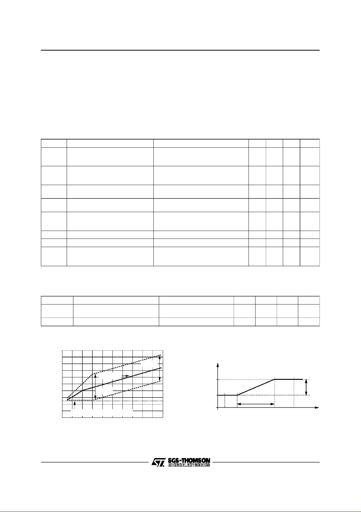
Tx Softclipping(see Figure 2)
Figure2 : TxSoftclipping and Distortion
at I
=20mA
L
2
V
LINE
Distortion
1
)
0.5
RMS
(V
L
V
0.2
0.1
0.05
0.2 0.5 1 2 5 10 20 100
(mV
V
MIC1-MIC2
RMS
)
50
12
10
8
6
4
2
0
) (%)
L
D(V
7092-04.EPS
6/24
TEA7092
TRANSMIT CHARACTERISTICS (continued)
Maximum Level on Line in Tx (see Figure 3)
The minimumoperating voltage of the TEA7092is 2.5V. At low line currentvalue, when the voltageover
the TEA7092is low, thesoftclippingfunctionautomaticallylimitsthe AC dynamicto avoidto reach the 2.5V
limit on the TEA7092.
When the DCvoltageover the TEA7092is high enough, the AC dynamicis limitedat a valuefixed by the
external resistor RSOFTconnectedon PinSOFTL.
The Valueof RSOFT is performed by : RSOFT= (RS x 50E
-6
- 0.8- VacPeak)/ 40E
-6
Tx Characteristics (T
=25°C,f = 1kHz,seeTest 3)
amb
Symbol Parameter Test Conditions Min. Typ. Max. Unit
Gtl
Transmit gain in Handset Mode V
Gtsm
Transmit gain in Handsfree Mode V
Ghl
Ghfm
Gt-6dB Transmit Gain
(-6dB intransmit path)
Zmic
Zhf
Ntx
Nhf
Handset Mic Input Impedance
Handsfree MicInput Impedance
Transmit Noise in Handset Mode
Transmit Noise in Handsfree Mode
Mmic Microphone Mute V
V
Lpeak
Transmit SoftclippingLevel See Figure 2, Vem= -42dBV, IL= 20mA 1.0 1.4 1.8 Vpeak
Transmit Distortion I
Dtx1
Dtx2
Squelch on Transmit Channel (T
amb
=25°C,f = 1kHz, IL=20mA, seeTest3)
= -48dBV
em
= 20mA
I
L
= 90mA
I
L
= -28dBV, Code 0110010
hfin
= 20mA
I
L
= 90mA
I
L
= -48dBV, IL= 20mA
V
em
Code 0110110
Between Pins MIC1, MIC2
Between HFIN and V
= 20mA, Code 0110010
I
L
2kΩ between MIC1 & MIC2
2kΩ between HFIN & V
= -48dBV, IL= 20mA 60 dB
em
= 20mA, see Figure 2
L
= -48dBV
V
em
= -36dBV
V
em
REF
REF
443745394641dB
241725192621dB
567dB
301540205025kΩ
-75
-75
dB
dB
kΩ
dBmp
dBmp
1
%
5
%
The principle of the squelch is to reduce the transmitgain as soon as the amplitude of the signal on the
microphoneis lower than a fixed thresholdvoltage, VT2.
Symbol Parameter Test Conditions Min. Typ. Max. Unit
Gtlmax
Gtlmax-Gsq
Transmit Gain V
em1
V
em2
= -75dBV
= -65dBV
36
45
Gsq Gain Variation See Figure 4 / 9 dB
dB
dB
Figure 3 : Line PeakVoltage versus DC Line
Current
10
V
AC Pe a k
(V)
L
V
8
6
4
2
2.5V Min. Line Pea k Voltage
V
20 40 60 80 1000
DC Mask
AC Peak
IL(mA)
Figure4 : TransmitGain versus Microphone
AC Input Signal
Trans mit
Gain (dB)
Gtlmax
Gtlmax - Gsq
7092-05.EPS
V
em1
Dgt
V
T1
V
T2
Microphone AC Voltage
V
em2
Gst
V
(dBV)
7/24
em
7092-06.EPS
TEA7092
RECEIVECHARACTERISTICS (T
=25°C,f = 1kHz)
amb
Symbol Parameter Test Conditions Min. Typ. Max. Unit
Eff Sidetone Efficiency Test 3, V
Gain
Test 2
Grl
Grs
Grs+6
+6dB Code [0010110]
Distortion Test 2, I
Drx1
Drx2
Nrx Noise Test 2, I
Mrx Mute Test 2, I
Z
Z
OUT
Input Impedance Between Pins SNSL & SNLL 120 150 kΩ
IN
Output Impedance 5 Ω
I
I
I
V
V
= -48dBV, IL= 20mA 26 dB
em
= 20mA
L
= 90mA
L
= 90mA
L
= 20mA
L
= -3dBV
ear
= 0dBV
ear
= 20mA -76 dBmp
L
= 20mA, VL= -9dBV 60 dB
L
5
-1.2
5
6
0.8
6
7
2.8
7
3
5
dB
dB
dB
%
%
The sidetoneof theTEA7092usestwo networks,these twonetworksareinternallymixedbetweenlongline
lengthand short line length.
The following equation givesthe sidetone impedanceversus linecurrent: ZAL = K x ZALL+ (1 - K)x ZASL
K=1forI
=ILL ;K= 0 forIL=ISL,and K varieslinear l ybetween1 and0 when ILvari esbetweenILL and ISL.
L
It is possibleto use only the standardone sidetone conceptby short-circuitedPins SNSL ans SNLL.
Gain Control Inhibition FacilityFor PABXApplication
(T
=25°C,IL=20mA, f = 1kHz / NoAGC mode selected 0010100)
amb
Symbol Parameter Test Conditions Min. Typ. Max. Unit
Gtp Transmit Gain Test 2 Gtl - 3 Gtl- 2 Gtl -1 dB
Grp Receive Gain Test 3 Grl- 3 Grl - 1.4 Grl - 0.5 dB
LOUDSPEAKERAMPLIFIER PART
LoudspeakerAmplifier Channel (T
=25°C,f = 1kHz, RLS=50Ω, Vem=0)
amb
The Loudspeakeramplifier channelhas a maximumgain of 35dBbetween Pin LSIN and Pin LSOUT. This
gain is programmablethrough the serialbus interface, 7 stepsof 4dB each.
To avoid distortion, the output level on the loudspeaker is controlled by a softclippingfunction, the time
constant of thisfeature is connectedto LSSOF pin.
Symbol Parameter Test Conditions Min. Typ. Max. Unit
GAIN VHP/Vac Test 4 IL = 20mA
GLS0 GMAX Code: (0 1 0 0 1 1 1) 33.5 35 36.5 dB
GLS1 GMAX-4dB Code: (01 0 0 1 1 0) 29.5 31 32.5 dB
GLS2 GMAX-8dB Code: (01 0 0 1 0 1) 25.5 27 28.5 dB
GLS3 GMAX-12dB Code: (01 0 0 1 0 0) 21.5 23 24.5 dB
GLS4 GMAX-16dB Code: (01 0 0 0 1 1) 17.5 19 20.5 dB
GLS5 GMAX-20db Code: (0 1 0 0 0 1 0) 13.5 15 16.5 dB
GLS6 GMAX-24dB Code: (01 0 0 0 0 1) 9.5 11 12.5 dB
GLS7 GMAX-28dB Code: (01 0 0 0 0 0) 5.5 7 8.5 dB
Mls Mute Loudspeaker Test 4 -30 dB
lsin Input Impedance 30 40 50 kΩ
PLS1
PLS2
Output Power Test 4, Gain= GLS0, V
IL= 20mA, D ≤ 2%
= 90mA, D ≤ 2%
I
L
= 0.15V
IN
RMS
13
40
18
55
mW
mW
8/24
 Loading...