

RGB HIGH VOLTAGE VIDEO AMPLIFIER
.
BANDWIDTH : 10MHzTYPICAL
.
RISE ANDFALL TIME: 50nsTYPICAL
.
CRT CATHODES CURRENT OUTPUTS FOR
PARALLEL OR SEQUENTIAL CUT-OFF OR
DRIVEADJUSTMENT
.
FLASHOVERPROTECTION
.
POWER DISSIPATION : 3.5W
.
ESD PROTECTED
TEA5101B
PRELIMINARY DATA
DESCRIPTION
The TEA5101B includes three video amplifiers
desi-gnedwith a high voltageDMOS/bipolar technology. It drives directly the three CRT cathodes.
The deviceis protected againstflashovers. Due to
its three cathode current outputs, the TEA5101B
canbe usedwithboth parallel andsequentialsamplingapplications.
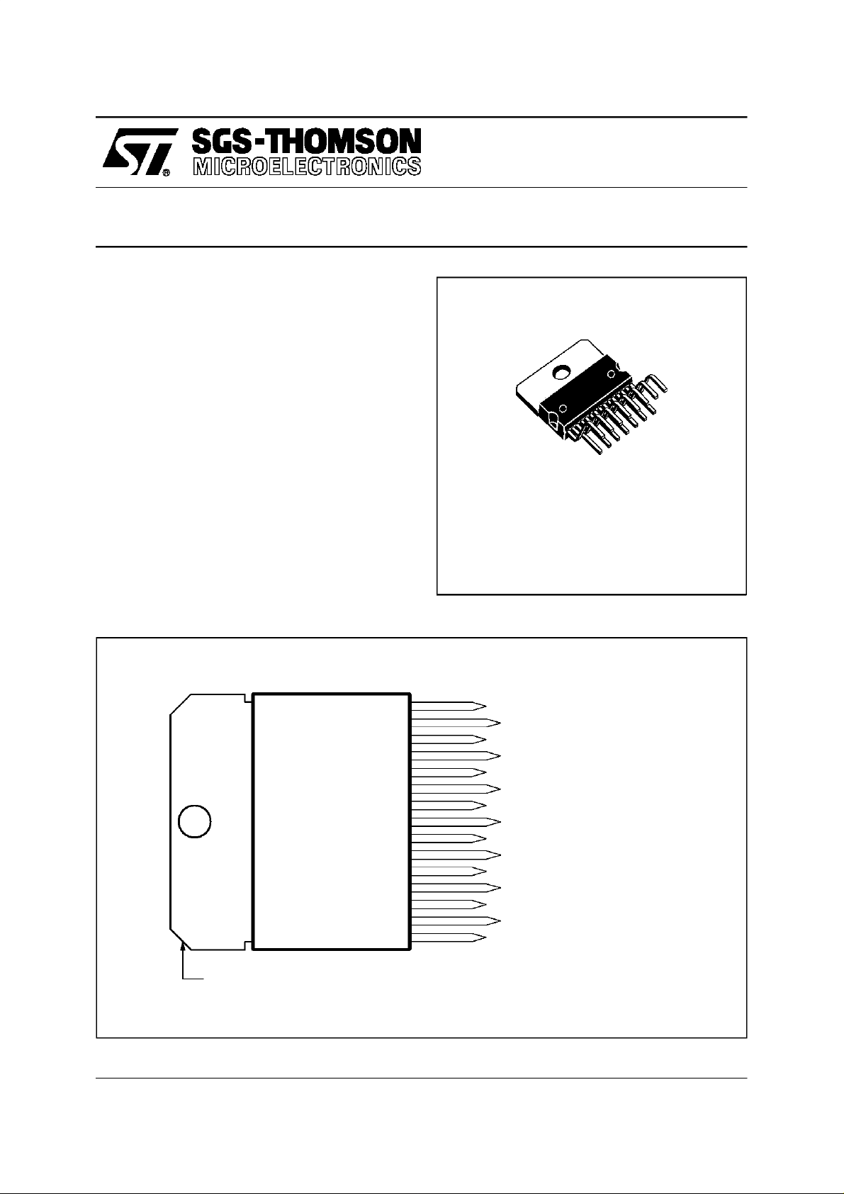
PINCONNECTIONS (topview)
15
14
13
12
11
10
9
8
7
6
5
4
3
2
1
MULTIWATT 15
(Plastic Package)
ORDER CODE : TEA5101B
BLUE FEEDBACK
BLUE CATHODE CURRENT
BLUE OUTPUT
GREEN FEEDBACK
GREEN CATHODE CURRENT
GREEN OUTPUT
RED FEEDBACK
GROUND
RED OUTPUT
RED CATHODE CURRENT
V HIGH VOLTAGE
DD
RED INPUT
GREEN INPUT
V LOW VOLTAGE
CC
BLUE INPUT
Tab connected to Pin 8
May 1996
This isadvance informationon a new product now in development or undergoing evaluation. Detailsare subject to changewithout notice.
5101B-01.EPS
1/6
TEA5101B
PIN FUNCTION
N° Function Description
1 Blue Input Input of the ”blue” amplifier. It is a virtualground with 3.8V bias voltage,
2V
CC
3 Green Input See Pin 1.
4 Red Input See Pin 1.
5V
DD
6 Red Cathode Current Provides the video processor with a copyof the DC current flowing into the red
7 Red Output Output driving the red cathode. Pin7 is internallyprotected against CRT arc
8 Ground Also connected to the heatsink.
9 Red Feedback Output driving the feedback resistor network for the redamplifier.
10 Green Output See Pin 7.
11 Green Cathode Current See Pin 6.
12 Green Feedback See Pin 9.
13 Blue Output See Pin 7.
14 Blue Cathode Current See Pin 6.
15 Blue Feedback See Pin 9.
15 microamperes input bias current with14kΩ input resistance.
Low voltage power supply, typically 12V.
Highvoltage power supply, typically 200V.
cathode, for automatic cut-off or gainadjustment. If this control is not used,
Pin 6 must be grounded.
discharges by a diode limiting the output voltage to V
DD
.
5101B-01.TBL
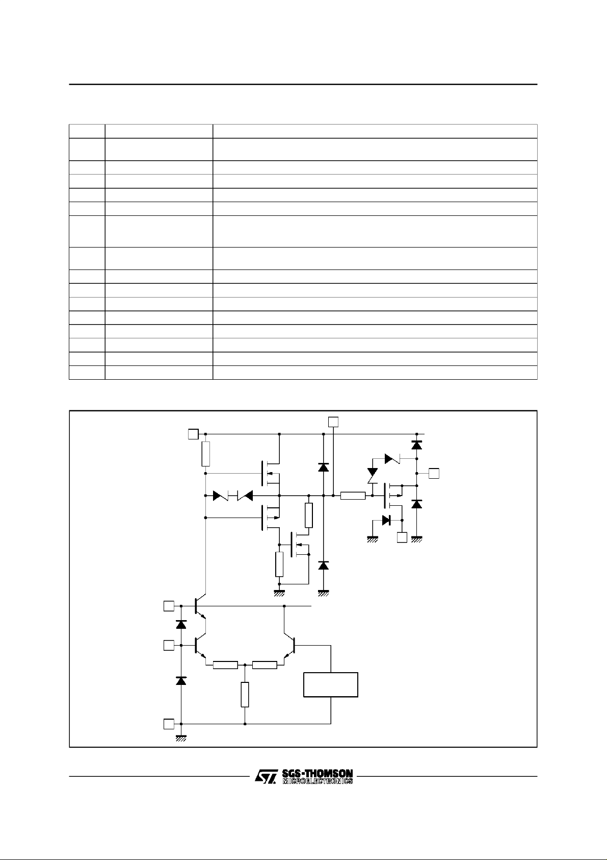
BLOCK DIAGRAM OF EACH CHANNEL
DD
5
40kΩ
2
1
(3, 4)
35Ω 35Ω
350
1kΩ
Ω
0.8kΩ
(12, 9)15V
20k
REFERENCE
VOLTAGE
13
Ω
(11, 6)
(10, 7)
14
2/6
GND
8
5101B-02.EPS
 Loading...