

SGS Thomson Microelectronics TEA2130 Datasheet
TEA2130
TV AND SATELLITE DECOD ER SC ANN ING PR OCESSO R
.
AUTOMATIC TIME CONSTANT SWITCHING
FOR VCR
.
DIGITAL VIDEO IDENTIFICATION CIRCUIT
.
500kHz RESONATOR OSCILLA T OR
.
NO LINE AND FRAME OSCILLATOR ADJUSTMENT
.
DUAL PLL FOR LINE DEFLECTION
.
SUPER SANDCASTLE OUTPUT
.
AUTOMATIC 50Hz/60Hz STANDARD IDENTIFICATION
.
EXCELLENT INTE RLACING CONTROL
.
FRAME SAFETY INPUT
.
FRAME SAWTOOTH GENERATOR
.
FULLY ESD A ND LATCH-UP PROT ECT E D
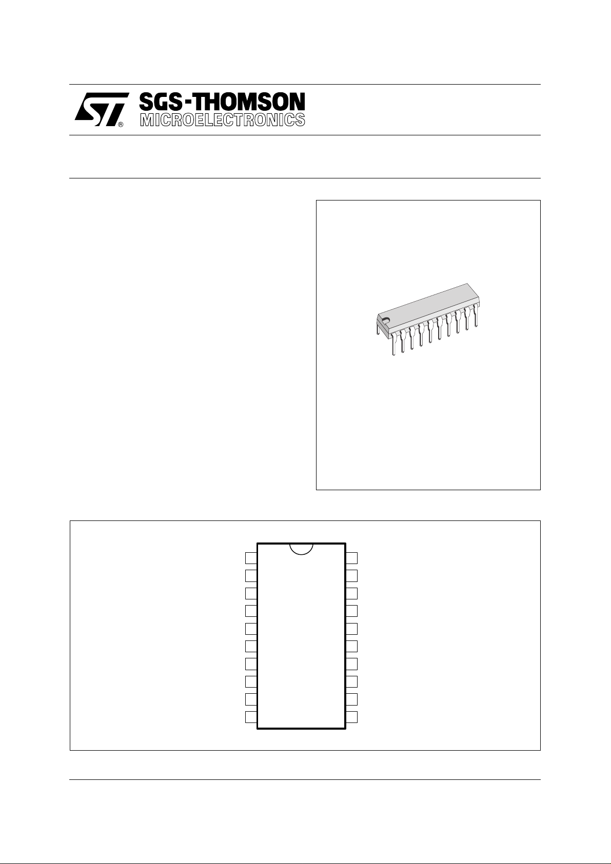
DIP20
(Plastic Package)
DESCRIP TION
The TEA2130 is a complete (horizontal and vertical) deflection processor, for TV applications and
all applications which require a flexible, high performance scanning processor (Satellite Decoder,
Video Multimedia).
PIN CONNECTIONS
REFERENCE VOLTAGE
VCR DETECTOR OUTPUT
Φ1 FILTER
GROUND
V
FRAME SAFETY INPUT
IDENTIFICATION OUTPUT
LINE SAW-TOOTH
CURRENT REFERENCE
LINE MONOSTABLE CAPACITOR
CC
1
2
3
4
5
6
7
8
9
10
20
19
18
17
16
15
14
13
12
11
ORDER CODE : TEA2130
NOISE MEASUREMENT OUTPUT
VIDEO INPUT
50% CAPACITOR
VCO INPUT
FRAME SAW-TOOTH GENERATOR
FRAME SAW-TOOTH OUTPUT
2 FILTER
Φ
LINE FLYBACK INPUT
SUPER SANDCASTLE OUTPUT
LINE OUTPUT
September 1993
2130-01.EPS
1/8
TEA2130
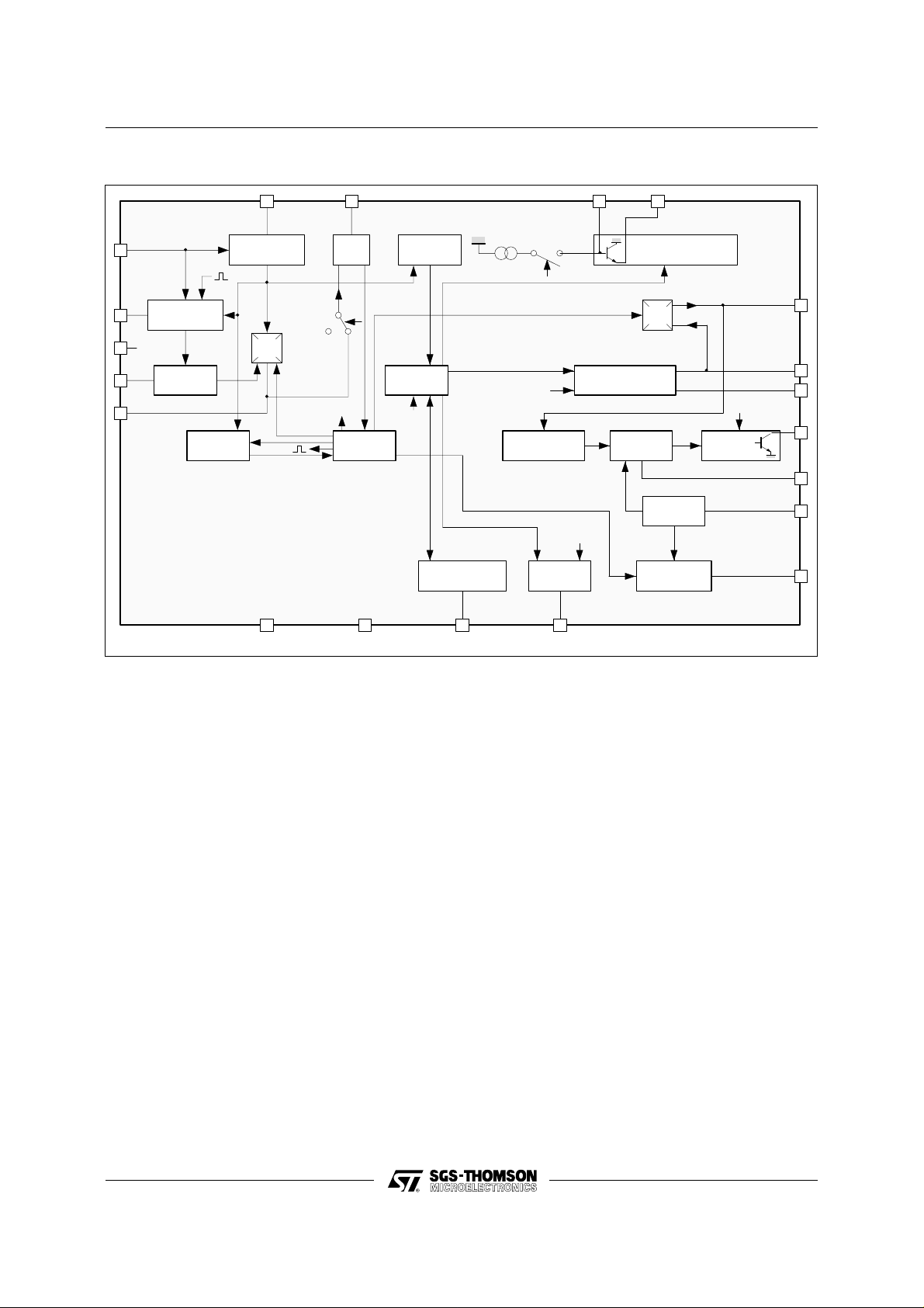
BLOCK DIAGRAM
19
20
1
2
3
NOISE
MEASURMENT
V /2
CC
AUTO VCR
SWIT CH
2µs
DIGITAL MU T
LINE SYNCHRO
SEPARATOR
LS
Φ
1
2µs
Mute
GND
V
REF
500kHz
Burst
ϕ1
1718
VCO
500kHz
Mute
LINE LOGIC
V
CC
ϕ2
FRAME
SEPARATOR
FRAME
LOGIC
Mute
FRAME SECURITY
DETECTION
50/60Hz
6754
Ident 60Hz
Burst
PHASE CONTR O L
LINE OUTPUT
50/60Hz &
MUT OUTPUT
FRAME SAWTOOTH
SUPER SAND
CASTL E G ENERATO R
LINE
MONOST
1.3V
REFERENCE
Mute
RAZ
LINE SAWTOOTH
GENERATOR
1516
GENERATOR
RAZ
Φ
2
VOLTAGE
Inhibition
LINE
OUTPUT
1.3V
14
13
12
11
10
9
8
2130-02.EPS
GENERAL DES CRI PTI O N
Introd uction
This integrated c ircuit us es high dens ity I2L bipolar
technology and combines analog signal processing with digital processing.
Timing signals are obtained from a voltage-c ontrolled oscillator (VCO) operating at 500kHz by means
of a cheap ceramic resonator. This avoid the frequency adjustment normally required with line and
frame oscillators.
A chain of dividers and appropriate logic circuitry
produces very accurate defined sampling pulses
and the necessary timing signals.
Internal Functi o ns
- Horizontal scanning processor
- Frame scanning proc essor
- B class frame output stage using an external
power amplifier with flyback generator
- Line and frame synchronization separation
- Dual phase-locked loop horizontal scanning
- High performance frame and line sync hronization
with interlacing control.
- Supersandcastle generator with reduced burst
gate pulse for 60Hz
- Automatic 50Hz / 60Hz standard identification
- Frame saw-tooth generator
- Digital video identification circuit
- Very steady free running mode of the line and
frame oscillator when no video is detected. This
allows on screen display without phase Jitter in
research mode of the tuner
- Automatic VCR mode recognition for time constant switching
- Frame safety input
WORKING DES CRI PT IO N
Synchronization Separator
Line synchronization separator is clamped to black
level of input video signal with synchronization
pulse bottom level measurement.
The synchronization pulses are divided centrally
between the black level and the synchronization
pulse bottom level, to improve performance on
video signal in noise conditions.
2/8

TEA2130
Frame Synchronizatio n
Frame synchroniz ation is fully integrate d (no external capacitor required).
The frame timing identification logic permits automatic adaptation to 50-60Hz standards or non-interlaced video.
An automatic synchronization window width system provides:
- Fast frame capture (7.3ms wide window)
- Good noise immunity (0.4ms narrow window)
The internal generator starts the discharge of the
sawtooth generator capacitor, so that it is not disturbed by line flyback effects .
Thanks to the logic control, the beginning of the
charge phase does not depend on any disturbing
effect of the line flyback . A 32µs timing is automatically applied on standardized transmissions for
perfect interlacing.
In VCR mode, the discharge time is controlled by
an internal monostable independent of the line
frequency and gives a direct frame synchronization.
Horizontal Scanning
The horizontal scanning frequency is obtained from
the 500kHz VCO.
The circuit uses two PL L:
- The first one controls the frequency
- The second one controls the relative phase of the
output line pulse and the line flyback signals.
The output pulse has a constant duration of 29µs,
independent of V
and of any delay in switching-
CC
off the scanning transistor.
Supersandcastle Generator
This output delivers a 3 level synchronization signal:
- Burst level
- Line blanking level
- Frame blanking level
In the event of vertical scanning failure, the frame
blanking level goes high to protect the tube.
Frame Scanning
The current to charge the frame sawtooth generator is automatically switched to 60Hz operation t o
maintain constant amplitude.
Automatic VCR Mode Recog n ition for Tim e
Constant Switching
- A third phase comparator is used to detect VCR
signals and to switch the φ1 short time constant.
- A noise level measurement is realized on the
video synchronization pulse to inhibit the short
time constant if the noise level is superior to an
adjustable threshold.
- VCR signals are detected if peak to peak signal
on pin 2 is superior to an internal threshold.
This threshold is depending on the noise level. So
with a no noisy video signal, the auto VCR switch
sensitivity is maximum, and it decreases when th e
noise increases.
- The sensitivity of the noise gate and the auto VCR
switch is adjustable by external resistance.
- Long and short time constants can be selected
manually by Pin 20.
Digital Video Ident ificati on
A digital circuit controls the identification signal.
When identification signal is low, the line oscillator
is set on a reference frequency . When identificat ion
signal is high, φ1 is locked and the c atch ing phase
can start. So that, the TEA2130 allowed on screen
displays in a steady way even without video signal
(during tuner research for example).
Identificati o n Ou tp ut
The identification function provides three different
levels :
- 0V : No video identification
- 6V : 60Hz video identification
- 12V : 50Hz video identification
This information may be used for timing research
in the case of frequency or voltage s ynthetizer type
receivers and for audio muting.
ABSOLUTE MAXIMUM RATINGS
Symbol Parameter Value Unit
CC
16
11
13
AMB
Supply Voltage 13.5 V
Pulse/Frame Sawtooth Generator Voltage VCC - 3 V
Output Current 40 mA
Input Current ± 5 mA
Operating Ambient Temperature 0 , + 70
V
V
I
I
T
THERMAL DATA
Symbol Parameter Value Unit
R
th(j-a)
Junction-ambient Thermal Resistance 80
o
o
C/W
C
2130-01.TBL
2130-02.TBL
3/8
 Loading...