

TDA7476
CAR RADIO DIAGNOSTIC PROCESSOR
PRELIMINARY DATA
WIDEOPERATINGVOLTAGERANGE
ST-BYFUNCTION (C-MOS)
LOW QUIESCENT ST-BY CURRENT CON-
SUMPTION
I2C BUS INTERFACE WITH 2 EXTERNALLY
SELECTABLEADDRESSES
UP TO 5 BTL EQUIVALENT INPUTS FOR
FAULT DETECTION IN THE AUDIO CHANNELS
- shortto GND
- shortto Vs
- shortacross the load (at turn-on)
- openload (at turn-on)
2 AUX INPUTS FOR FAULT DETECTION IN
THE ANTENNA AND BOOSTERS SUPPLY
LINE
- shortto GND
- openload
WARNING PIN FUNCTION (interrupt facility)
ACTIVATED IN THE FOLLOWING CONDITION:
- audiochannelshorted to V
S
- audiochannelshorted to GND
- aux input shorted to GND
NOISEFREE DIAGNOSTICSOPERATION
PROTETCTORS
LOADDUMP VOLTAGE
MULTIPOWER BCD TECHNOLOGY
SO24
OPENGND
REVERSEDBATTERY
ESD
DESCRIPTION
The car radio diagnostic processor is an interface
chip in BCD Technology intended for car radio
applications. It is able to detect potential faults
comingfrom any misconnectionin thecar radio or
in the harnesswhen installingthe set.
The device is able to reveal any fault in the loudspeaker lines and in the antenna and booster
supply lines, providing a proper output signal (I
2
C
bus compatible) in order to disable the ICs under
fault and/or to alert µcontroller by means of warning messages.
PIN CONNECTION (Topview)
GND
SDA
SCL
ADD
W
AUX1 OUT
AUX1 IN
AUX2 IN
AUX2 OUT CH1-
5V CH1+
ST-BY T-CAP11 14
S
December 1999
This is preliminary information on a new product now in development or undergoingevaluation.Details are subject to change without notice.
2
3
4
5
6
7
8
9
10
D97AU570
24
23
22
21
20
19
18
17
16
15
1312V
CH5-1
CH5+
CH4+
CH4CH3CH3+
CH2+
CH2-
CURR. SET. RES.
1/15
TDA7476
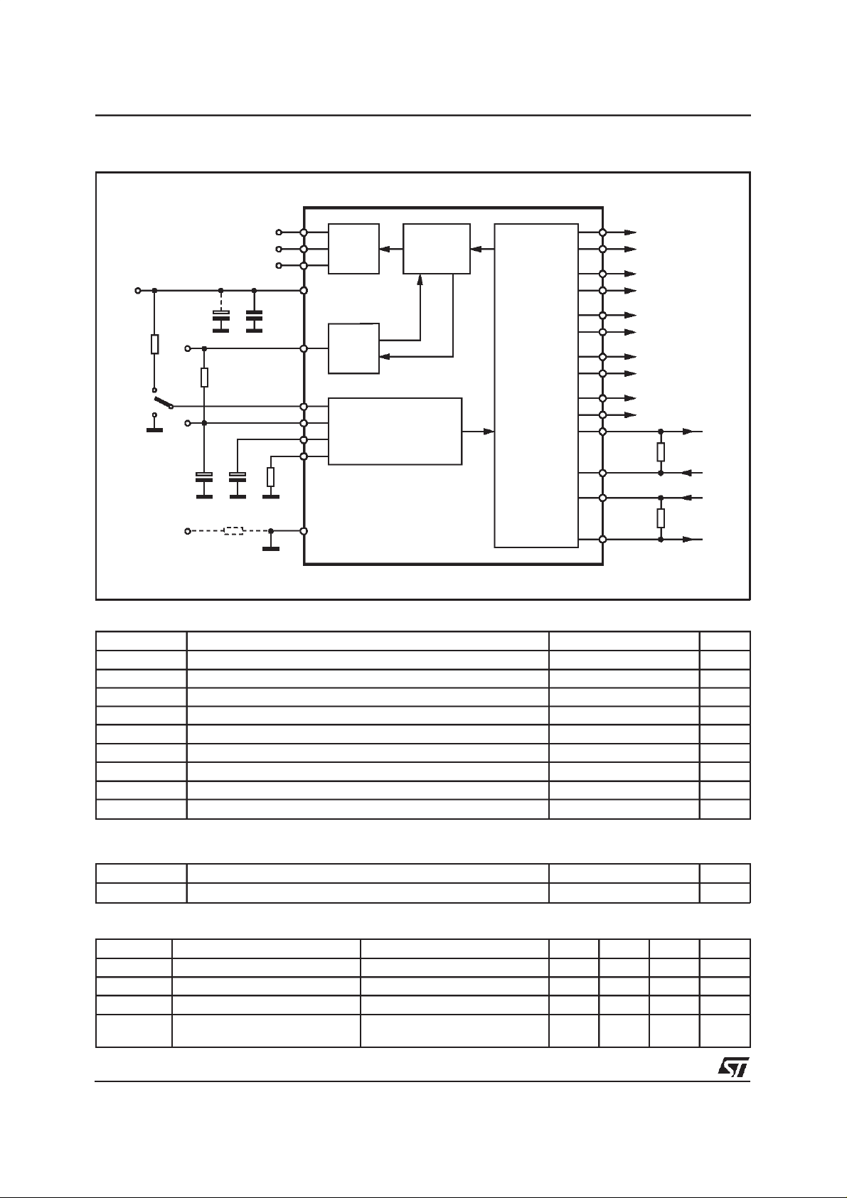
BLOCK DIAGRAM
SDA
SCL
ADD
V
S
C2
100nF
R
C
CS
T
R3
10KΩ
ST-BY
SW1
10KΩ
10∝F
DIG-GND
R4
C1
W
5V
REF
C3
10µF
R5 51Ω
ABSOLUTE MAXIMUM RATINGS
2
3
I2C INTERFACE
4
12
5
DELAY
CURRENT
FORCING
11
10
VOLTAGE
14
TEST SIGNAL GENERATOR
13
19
REGULATOR
&
&
COMPARATORS
24
23
22
21
20
19
18
17
16
15
6
7
8
RSENS1
RSENS2
D96AU499A
CH5
CH4
CH3
CH2
CH1
OUT
AUX1
IN
IN
AUX2
OUT
Symbol Parameter Value Unit
V
V
V
peak
P
T
stg;Tj
V
V
V
V
op
s
tot
SB
SDA
SCL
ADD
Operating Supply Voltage 18 V
DC Supply Voltage 28 V
Peak Supply Voltage t = 50ms 40 V
Total PowerDissipation Tcase = 25°C 1.5 W
Storage and Junction Temperature -40 to 150 °C
Stand-by Pin Voltage 6 V
SDA PinVoltage 6 V
SCL Pin Voltage 6 V
ADD Pin Voltage 6 V
THERMAL DATA
Symbol Parameter Value Unit
R
Th j-amb
ELECTRICALCHARACTERISTICS
Symbol Parameter Test Condition Min. Typ. Max. Unit
IN Stand-By IN Threshold 1.5 V
V
SB
OUT Stand-By OUT Threshold 3.5 V
V
SB
I
SB
Iq Total Quiescent Current Total quiescent Current with
Thermal resistance junction to ambient Max. 85 °C/W
= 14.4V;T
(V
s
=25°;RL=4Ω, unlessotherwise specified.)
amb
Stand-By Current Consumption Stand-By Voltage Pin = 1.5V 100 µA
5mA
TDA7476 not addressed
2/15
TDA7476
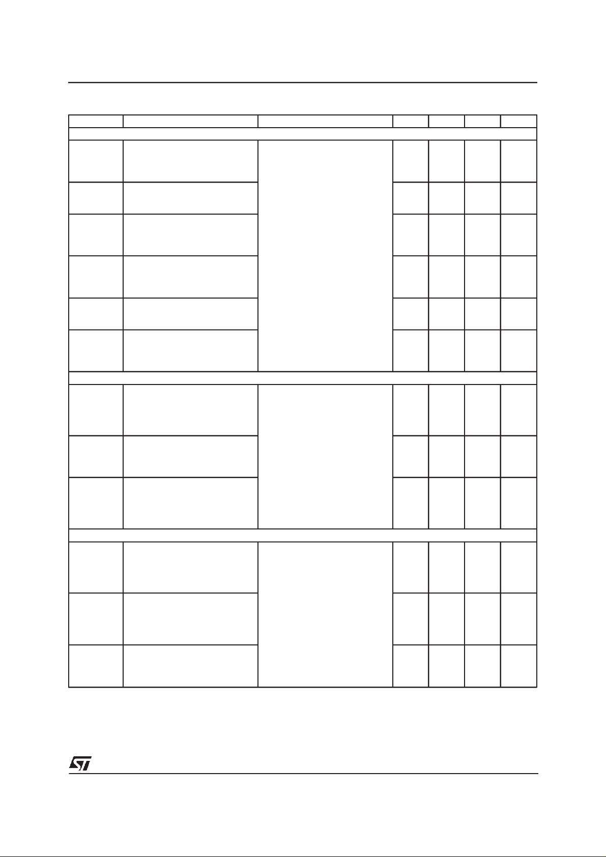
ELECTRICALCHARACTERISTICS (continued)
Symbol Parameter Test Condition Min. Typ. Max. Unit
AUDIO INPUTS CH1, CH2, CH3, CH4,CH5 - TURN ON DIAGNOSTIC
Pgnd Short to GND det.(below this
limit, the Audio Output is
considerd in Short Circuit to
GND)
Pvs Short to Vsdet. (above this
limit, the Audio Output is
considered in Short Circuitto Vs)
Pnop Normal operation thresholds.
(Within these limits, the Audio
Output is considered without
faults)
Lsc Shorted Load det. (voltage
across the Audio Outputs).
Below this limit the load is
considered shorted.
Lop Open Load det. (voltage across
the Audio Outputs). Above this
limit the load is considered open.
Lnop Normal load det. (Voltage
across the Audio Output).
Within these limits the load
resistance is considered normal.
AUX INPUTS AUX1, AUX2 - TURN ON DIAGNOSTIC
Agnd Short to GND det.(voltage
across the sensing resistor).
Above this limit the AUX pin is
considered in Short Circuitto
GND.
Aol Open load det. (voltage across
the sensing resistor). Below this
limit the Aux pin is considered in
Open Load condition.
Anop Normal Operation det. (Voltage
across the sensing resistor).
Within these limits the load
resistance connected to the Aux
pin is considered correct.
AUDIO INPUTS - PERMANENT DIAGNOSTIC
Pgnd Short to GND det.(below this
limit, the Audio Output is
considered in Short Circuitto
Vs) This condition must be true
for a time higher than Tdel
Pvs Short to Vsdet. (above this limit
the Audio Output is considered
in Short Circuit to Vs) This
condition must be true for a time
higher than Tdel
Pnop Normal operation thresholds.
(Within these limits, the Audio
Output is considered without
faults)
Power amplifier in st-by
condition
High side driver ON 0.75 V
Power amplifier ON 0.8 V
Vs-0.7 V
1.2 Vs-1.3 V
550 mV
22 220 mV
0.125 0.5 V
Vs-0.7 V
1.2 Vs-1.3 V
0.8 V
5mV
0.085 V
3/15
TDA7476
ELECTRICALCHARACTERISTICS (continued)
Symbol Parameter Test Condition Min. Typ. Max. Unit
AUX INPUTS - PERMANENT DIAGNOSTIC
Agnd Short to GND det.(above this
limit, the Audio Output is
considered in Short Circuitto
Vs) This condition must be true
for a time higher than Tdel
Aol Open load det. (voltage across
the sensing resistor. Below this
limit the Aux pin is considered in
Open Load condition)
This condition must be true for a
time higher than Tdel
Anop Normal Operation det. (Voltage
across the sensing resistor.
Within these limits the load
resistance connected to the Aux
pin is considered correct)
PERMANENT DIAGNOSTIC - ACQUISITION TIME DELAY
Tdel Acquisition time delay- The
fault is considered true if the
fault condition are present for
more than Tdel without
interruption
PERMANENT DIAGNOSTIC - WARNINGPIN
Vsat Saturation voltage on pin 5 Sink Current at Pin 5 = 1mA 1 V
ADDRESS SELECT
V
ADD
2
I
C BUS INTERFACE
f
SCL
V
IL
V
IH
V
SAT
Voltage on pin 4 Address 0100010X 1.5 V
Clock Frequency 400 KHz
Input Low Voltage 1.5 V
InputHigh Voltage 3 V
Sat Voltage at pin 2 Sink Current at Pin 2 = 5mA 1.5 V
WORKINGPRINCIPLES
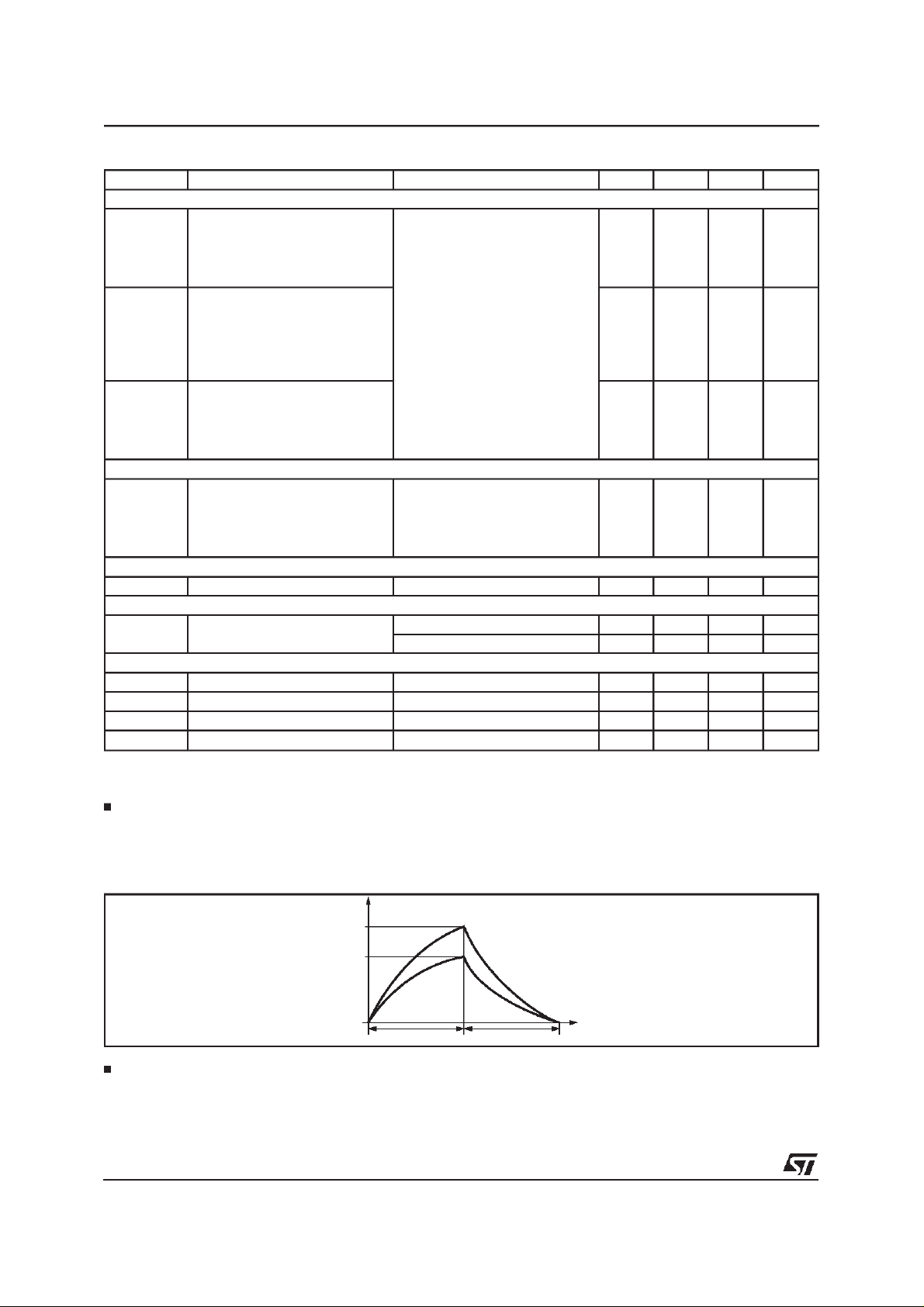
Turn-ondiagnostic - CH1, CH2, CH3,CH4, CH5 - Shorted load/openload detection
To detect a short across the load or an open load, a subsoniccurrent pulse is generated. The information related to the status of the outputs are measured and memorized at the top of the current
pulse (tm in fig.1). The current is sourced by the positive pins (CH1+,...CH5+) and it is sunk by the
correspondingnegativepins (CH1-,...CH5-).
Figure 1.
High side driver ON 0.75 V
0.085 V
0.125 0.5 V
2s
Address 0100011X 3 5 V
I(mA)
I
SOURCE
I
SINK
t
t
m
D97AU571
t
s
(ms)
Isink and Isource are dependingon the external resistor Rcs. The minimum allowed value for Rcs is
1.65KOhm.The relationshipamong Isink,Isource and Rcs is the following:
Isink = (3.3/Rcs)x 11
Isource= 1.5 x Isink
4/15
TDA7476
On bridge (or bridgeequivalent) devices if thereis no short circuit to GND or to Vs, Isourcegoes into
saturation mode (for Vout > 3V), and in the load flows Isink. As the turn-on diagnosticthresholds are
fixed, it is possible to calculatethe ranges of loudspeakerresistance in which short circuit, normal operation and openload are detected.
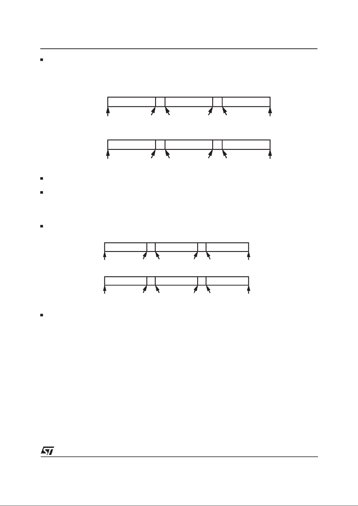
For example, here below are two cases,with Rcs = 3.3KOhm and Rcs = 1.8KOhm. (R
= Vthr*/Isink).
L
Rcs = 3.3kΩ
Rcs = 1.8kΩ
S.C. across Load x Open Load
0Ω 2Ω 20Ω infinite
S.C. across Load x Open Load
0Ω 1.1Ω 11Ω infinite
0.5Ω 50Ω
0.27Ω 27Ω
xNormal Operation
xNormal Operation
D96AU500
The exact values of the above mentioned resistive ranges may vary a little, depending on the power
amplifier used. These valuesfor the variouspossible ST power amplifierswill be communicatedlater.
When single-ended devices are used and the application circuit is as shown in fig. 5,6,it is necessary
to use:
- a greater timing capacitor so that the time t
m
is high andthe outputs of the amplifiers are able to rise
over1V;
- a resistorR
CS 1.5 times higher than thatused for the bridge amplifiers.
In this case, the loudspeaker resistance ranges in which short circuit, normal operation and openload
are detectedwill be as followswith Rcs = 4.7KOhmand Rcs = 2.7KOhm(R
Rcs = 4.7kΩ
S.C. across Load x Open Load
0Ω 1.9Ω 19Ω infinite
0.47Ω 47Ω
xNormal Operation
= Vthr/Isource)
L
Rcs = 2.7k
S.C. across Load x Open Load
Ω
0Ω 1.1Ω 11Ω infinite
0.27Ω 27Ω
xNormal Operation
D96AU501
The exact values of the above mentioned resistive ranges may vary a little, depending on the power
amplifier used. These valueswill be communicatedlater.
Turn-ondiagnostic - CH1, CH2, CH3,CH4, CH5 - Short to GND and Vs.
To detect if there is short circuit to GND or Vs, the subsonic current pulse is exploited. The information
related to the status of the outputsare measured and memorized at the top of the current pulse (tm in
fig.1).If no faults are present,the pins connectedto the audio outputs (CH1,..CH5) will reach about 3V.
If one or more outputsare shorted to GND,these voltagesbecomelower than 3V.
If one or more outputsare shorted to Vs, the output voltageincreases over 3V.
The fault status can be know by sensing the output voltages. The reason way voltage threshold has
been preferred instead of a currentthreshold to declareshort circuit resistorranges is two fold:
1) The amplifier can draincurrent in the resistive path of the short circuit, hence this current and consequentlythe short circuit resistor cannot be determinedwith a sufficientlevel of accuracy.
2) The voltage differencebetweenthe car radio ground (reference)and the position of the chassis of the
car where the loudspeaker line is connected (due to an accidental short circuit) can be up to some
hundredsof mV. This doesnot permit a correctmeasure of the short circuit resistor.
(*) Vthr is the threshold described in the table on page 3/14 - 4/14 (for example Pgnd-min, Pvs - max, Pnop - min,Pnop - max etc..)
5/15
 Loading...