

SGS Thomson Microelectronics TDA7473 Datasheet
QUAD BTL DRIVER WITH VOLTAGE REGULATOR
4 BUILT-INPOWERBRIDGES(4 x 0.6A)
NO EXTERNAL COMPONENTS
SINGLEPOWERSUPPLY
WIDESUPPLY VOLTAGE RANGE (6 TO15V)
5V REGULATOR DRIVER FOR EXTERNAL
PASS TRANSISTOR WITH FOLD-BACK
SHORTCIRCUIT PROTECTION
ADJUSTABLE REGULATOR (2.0 TO 3.6V @
200mA) WITH SHORT CIRCUIT PROTECTION
TDA7473
SO28 (24+2+2)
DESCRIPTION
This device is a quad power driver circuit in BTL
configuration, intended for use as a power driver
for servo systems with a singlesupply.
It’s specially dedicated to compact disc players
and it’s capable of driving focus & tracking actuators sledge & spindle motors.
The regulators are mainly used to have a 5V supply for the power part and a lower programmable
voltagefor the logic circuits.
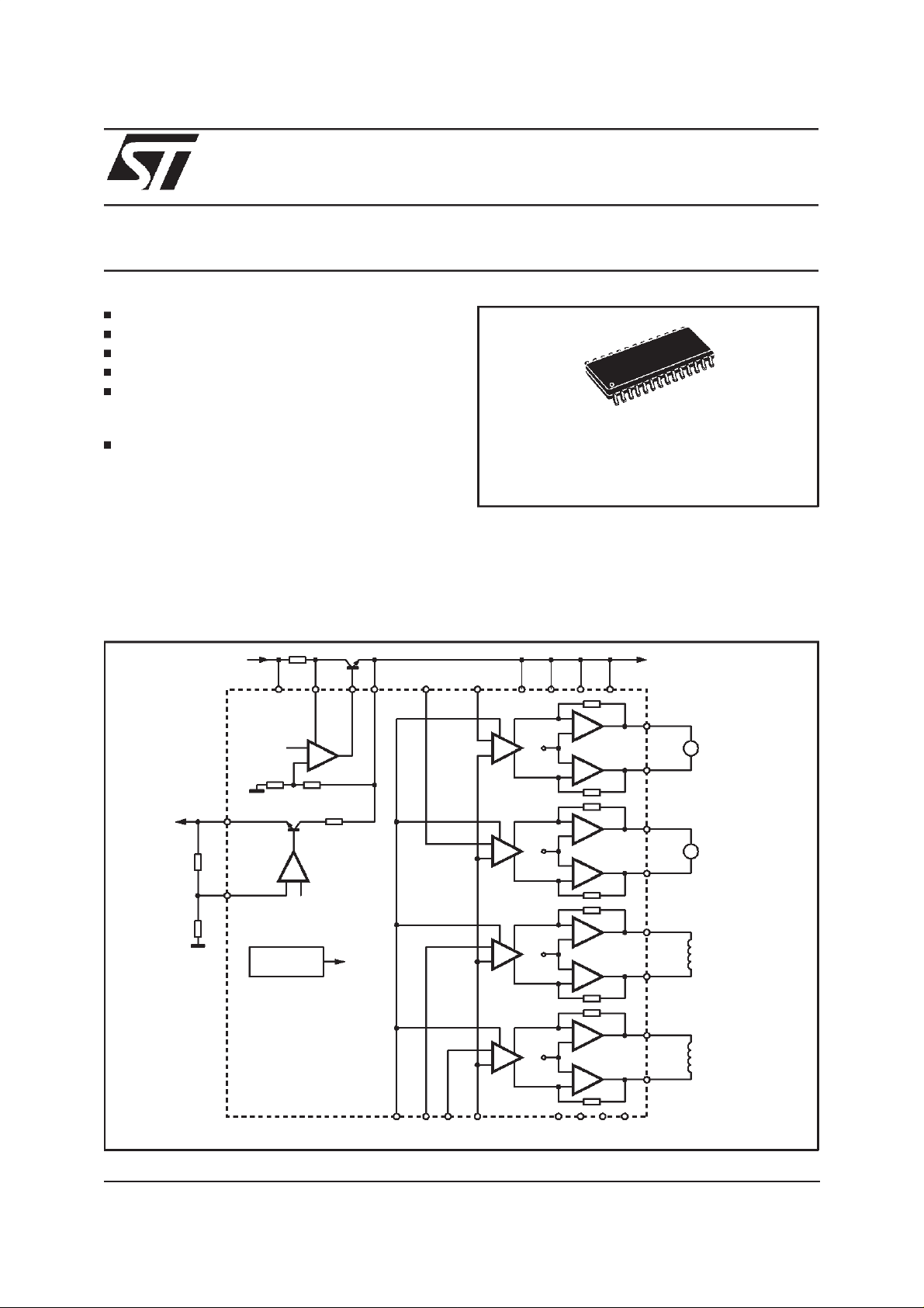
Figure 1: Quad BTL PowerBridges + MultifunctionRegulators.
+
R1
1K
R2
1K
REG
ADJ
VSUP
VBG
REFERENCE
OC
VBG
VBG
5V
VS1 VS2
+
-
+
-
+
-
VS/2
VS/2
VS/2
VS3IN2 IN1DRIV
VS4
-
+
+
-
-
+
+
-
-
+
+
-
OUT 1+
OUT 1-
OUT 2+
OUT 2-
OUT 3+
OUT 3-
SPINDLE
M
MOTOR
SLEDGE
M
MOTOR
TRACKING
ACTUATOR
June 1998
IN3
ST_BY IN4
COMM
REF
-
+
VS/2
+
-
+
-
GND GND GND GND
OUT 4+
OUT 4-
D95AU223B
FOCUS
ACTUATOR
1/5

TDA7473
PIN CONNECTION (Topview)
5V
VSUP
OUT1-
VS1
OUT1+
GND
GND
ADJ
OUT2+ OUT3+
VS2
OUT2- OUT3-
ST_BY
REG
2
3
4
5
6
7
8
9
10
11
12
13
D95AU310A
28
27
26
25
24
23
22
21
20
19
18
17
16
1514
PIN FUNCTIONS
N. Pin Name Description
1 5V 5V regulated input
2 VSUP Positive power supply(battery)
3 OUT1- 1.st channel negative output
4 VS1 1.st channel power supply
5 OUT1+ 1.st channel positive output
6 OC Overcurrent sense input
7 GND Ground
8 GND Ground
9 ADJ Regulated voltage adjust input
10 OUT2+ 2.nd channel positive output
11 VS2 2.nd channel powersupply
12 OUT2_ 2.nd channel negativeoutput
13 ST_BY Stand_by
14 REG Regulated voltage output
15 COMM Common negative input
16 IN2 Positive input for the 2.nd channel
17 OUT3- 3.rd channel negative output
18 VS3 3.rd channel power supply
19 OUT3+ 3.rd channel positive output
20 IN3 Positive input for the 3.rd channel
21 GND Ground
22 GND Ground
23 IN4 Positive input for the 4.th channel
24 OUT4+ 4.th channel positive output
25 VS4 4.th channel power supply
26 OUT4- 4.th channel negative output
27 IN1 Positive input for the 1.st channel
28 DRIV Pass transistor driver
DRIV1
IN1
OUT4VS4
OUT4+
IN4OC
GND
GND
IN3
VS3
IN2
COMM
2/5
 Loading...