

EQUALIZER CARRADIO SIGNAL PROCESSOR
■
3 STEREO INPUTS
■
3 MONO INPUTS
■
DYNAMIC-COMPRESSION-STAGE FOR CD
■
BASS, TREBLE AND LOUDNESS CONTROL
■
EQ-FILTER S FOR SEPARAT E FRONT/REAREQUALIZATION
■
VOICE-BAND-FILTER FOR MI XING-CHANNEL
■
DIRECT MUTE AND SOFTMUTE
■
INTERNAL BEEP
■
FOUR INDEPENDENT SPEAKER-OUTPUTS
■
INDEPEN DENT SECOND SOURCE-SE LECTOR
■
FULL MIXING CAPA BIL ITY
■
PAUSE DETECTOR
Stereodecoder
■
RDS MUTE
■
NO EXTERNAL ADJUSTMENTS
■
AM/FM NOISEBLAN KER WI TH SEVERAL
TRIGGER CONTROLS
■
PROGRAMMABLE MULTI PATH D ETECTOR
■
QUALITY DETECTOR OUTPUT
TDA7405
TQFP44
ORDERING NUMBER: TDA7405
Digital control:
■
I2C-BUS INTERFAC E
DESCRIPTION
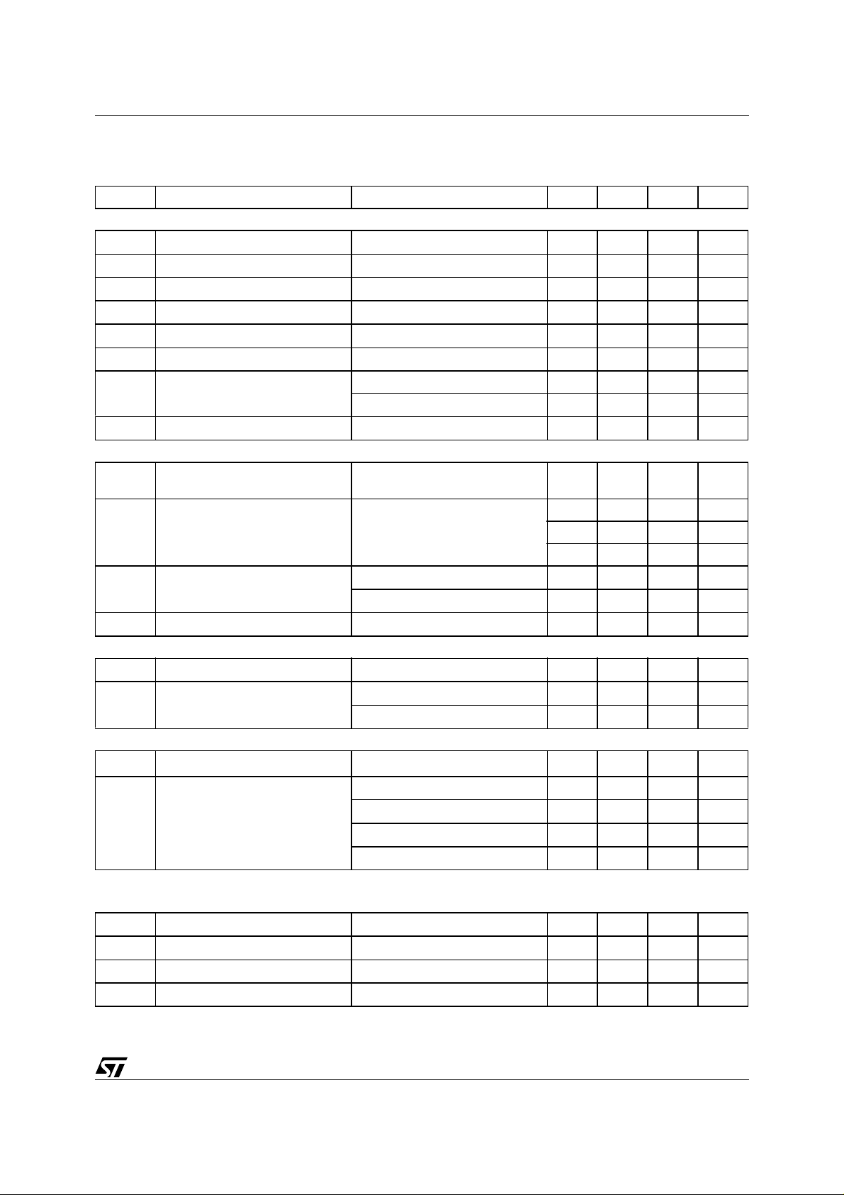
The devic e includes a high performanc e audiopr ocessor
and a st ereodecoder-noiseblanker combination with the
whole low frequency signal processing necessary for
state-of-the-art as well as future carradios. The digital
control allows a programming in a wide range of all the
filter characteristics. Also the stereodecoder part offers
several possibilities of programming especially for the
adaptation to different IF -devices.
BLOCK DIAGRAM
October 2001
1/56

TDA7405
SUPPLY
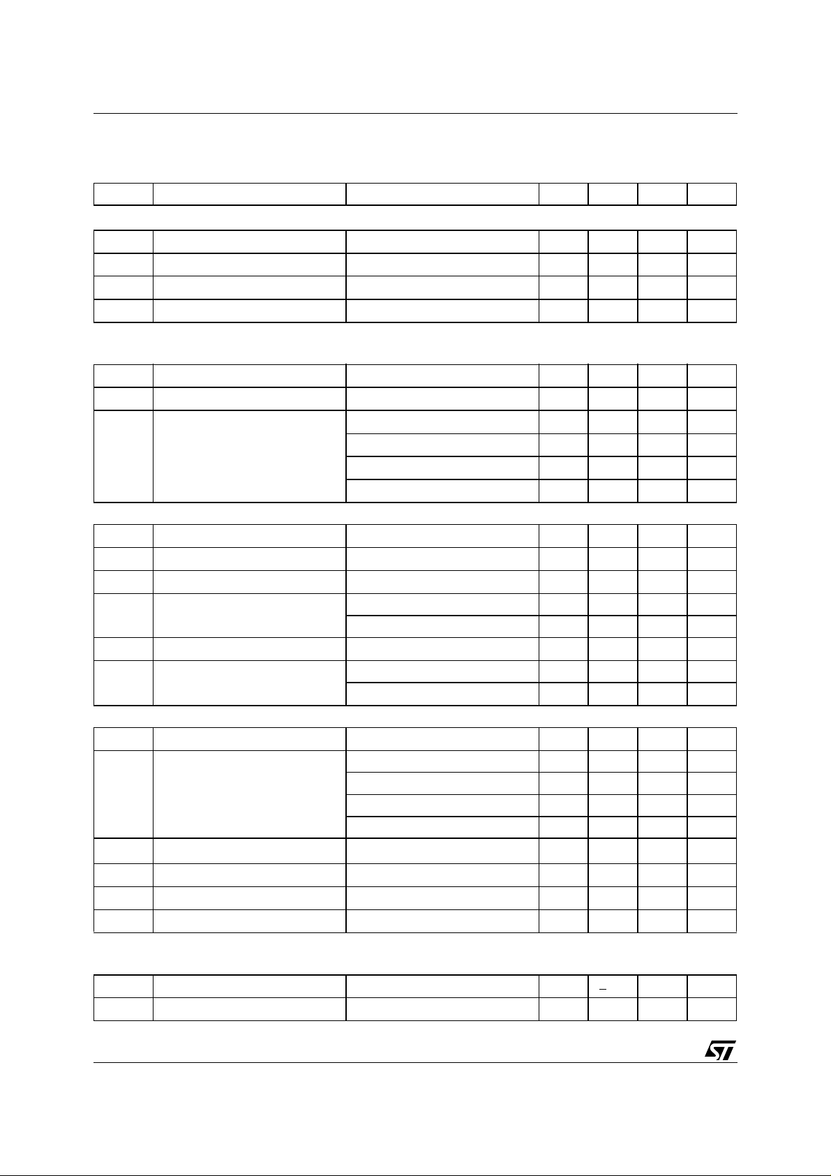
Symbol Parameter Test Condition Min. Typ. Max. Unit
V
Supply Voltage 7.5 9 10.5 V
s
I
Supply Current Vs = 9V 45 65 85 mA
s
SVRR Ripple Rejection @ 1KHz Audioprocessor(all Filters flat) 60 dB
Stereodecoder + Audioprocessor 55 dB
THERMAL DATA
Symbol Parameter Value Unit
R
Th j-pins
Thermal Resistance Junction-pins max 65 °C/W
ABSOLUTE MAXIMUM RATINGS
Symbol Parameter Value Unit
V
Operating Supply Voltage 10.5 V
s
T
T
Operating Temperature Range -40 to 85 °C
amb
Storage Temperature Range -55 to +150 °C
stg
ESD
All pins are protected against ESD according to the MIL883 standard.
PIN CONNECTION
(Top view
)
2/56

TDA7405
BLOCK DIAGRAM
(Enlarged view)
3/56

TDA7405
1 AUDIOPROCESSOR PART
Features:
Input Multiplexer 2 fully differential CD stereo inputs with programmable attenuation
1 single-ended stereo input
2 differential mono input
1 single-ended mono input
In-Gain 0..15dB, 1dB steps
internal Offset-cancellation (AutoZero)
separate second source-selector
Beep internal Beep with 3 frequencies + diagnostic setting (19kHz tone)
Mixing stage Beep, Phone,Navigation and FM mixable to all speaker-outputs (see Figure 20)
programmabe Voice-Band Filter
Loudness programmable center frequency and frequency response
15 x 1dB steps
selectable flat-mode (constant attenuation)
Volume 0.5dB attenuator
100dB range
soft-step control with programmable times
Bass 2nd order frequency response
center frequency programmable in 8 steps
DC gain programmable
± 15 x 1dB steps
Treble 2nd order frequency response
center frequency programmable in 4 steps
± 15 x 1dB steps
Equalizer two stereo equalizing-filters for separate front/rear adaption
1st filter center-frequency programmable i n 16 steps ( 4 steps/octav e, min 63Hz, max
840Hz)
2nd filter center-frequency programmable in 16 steps (4 steps/octave, min 300Hz,
max 4kHz)
quality factor programmable in 4 steps
± 15 x 1dB steps
selectable flat-mode
Speaker 4 independent speaker controls in 1dB steps
control range 95dB
separate Mute
Mute Functions direct mute
digitally controlled SoftMute with 4 programmable mute-times
Pause Detector programmable threshold
Compander dynamic range compression for use with CD
2:1 compression rate
programmable max. gain
4/56
TDA7405
Table 1. ELECTRICAL CHARACTERISTICS
(VS=9V; T
Symbol Parameter Test Condition Min. Typ. Max. Unit
INPUT SELECTOR
R
in
V
CL
S
IN
G
IN MIN
G
IN MAX
G
STEP
V
DC
V
offset
DIFFERENTIAL STEREO INPUTS
R
in
G
CD
CMRR Common Mode Rejection Ratio V
e
NO
DIFFERENTIAL MONO INPUTS
R
in
CMRR Common Mode Rejection Ratio V
BEEP CONTROL
V
RMS
f
Beep
MIXING CONTROL
M
LEVEL
G
MAX
A
MAX
A
STEP
=25°C; RL=10kΩ; all gains=0dB; f=1kHz; unless otherwise specified)
amb
Input Resistance all single ended Inputs 70 100 130 kΩ
Clipping Level 2.2 2.6 V
Input Separation 80 100 dB
Min. Input Gain -1 0 +1 dB
Max. Input Gain 13 15 17 dB
Step Resolution 0.5 1 1.5 dB
DC Steps Adjacent Gain Steps -5 1 5 mV
G
MIN
to G
MAX
-10 1 10 mV
Remaining offset with AutoZero 0.5 mV
Input Resistance
Differential 70 100 130 kΩ
(see Fig. 1)
Gain only at true differential input -1 0 1 dB
-5 -6 -7 dB
-11 -12 -13 dB
= 1V
CM
= 1V
V
CM
@ 1kHz 46 70 dB
RMS
@ 10kHz 46 60 dB
RMS
Output-Noise @ Speaker-Outputs 20Hz - 20kHz, flat; all stages 0dB 9 15 µV
Input Impedance D ifferential 40 56 72 kΩ
= 1V
CM
= 1V
V
CM
Beep Level Mix-Gain = 6dB 250
Beep Frequency f
1. The Level for the 19kHz-Testtone is 2.1V
RMS
Beep1
f
Beep2
f
Beep3
f
Beep4
@ 1kHz 46 70 dB
RMS
@ 10kHz 46 60 dB
RMS
1)
350
500 mV
470 500 530 Hz
740 780 820 Hz
1.7 1.8 1 .9 kHz
18 19 2 0 kHz
Mixing Ratio Main / Mix-Source -6/-6 dB
Max. Gain 13 15 17 dB
Max. Attenuation -83 -79 -75 dB
Attennuation Step 0.5 1 1.5 dB
RMS
5/56
TDA7405
Table 1. ELECTRICAL CHARACTERISTICS
(VS=9V; T
=25°C; RL=10kΩ; all gains=0dB; f=1kHz; unless otherwise specified)
amb
(continued)
Symbol Parameter Test Condition Min. Typ. Max. Unit
)
MULTIPLEXER OUTPUT
R
V
Output Impedance 800 1000 Ω
OUT
R
Output Load Capacitance 2 kΩ
L
C
L
DC Voltage Level 4.3 4.5 4.7 V
DC
2. If confgured as Multip le xer-Output
2
10 nF
LOUDNESS CONTROL
A
A
f
STEP
Peak
Step Resolution 0.5 1 1.5 dB
Max. Attenuation -21 -19 -17 dB
MAX
Peak Frequency f
P1
f
P2
f
P3
f
P4
180 200 220 Hz
360 400 440 Hz
540 600 660 Hz
720 800 880 Hz
VOLUME CONTROL
G
A
A
STEP
Max. Gain 30 32 34 dB
MAX
Max. Attenuation -83 -79.5 -75 dB
MAX
Step Resolution 0 0.5 1 dB
Attenuation Set Error G = -20 to +20dB -0.75 0 +0.75 dB
E
A
G = -80 to -20dB -4 0 3 dB
Tracking Error 2dB
E
T
V
DC Steps Adjacent Attenuation Steps 0.1 3 mV
DC
From 0dB to G
MIN
0.5 5 mV
SOFT MUTE
A
MUTE
Mute Attenuation 80 100 dB
Delay Time T1 0.48 1 ms
T
D
T2 0.96 2 ms
T3 70 123 170 ms
T4 200 324 600 ms
V
TH low
V
TH high
R
V
Low Threshold for SM-Pin
High Threshold for SM - Pin 2.5 V
Internal pull-up resistor 32 45 58 kΩ
PU
Internal pull-up Voltage 3.3 V
PU
3. The SM-Pin is active low (M ut e = 0)
3)
1V
BASS CONTROL
C
RANGE
A
STEP
Control Range ±14 +15.5 ±16 dB
Step Resolution 0.5 1 1.5 dB
6/56

TDA7405
Table 1. ELECTRICAL CHARACTERISTICS
(VS=9V; T
=25°C; RL=10kΩ; all gains=0dB; f=1kHz; unless otherwise specified)
amb
(continued)
Symbol Parameter Test Condition Min. Typ. Max. Unit
f
Q
DC
C
BASS
GAIN
Center Frequency f
Quality Factor Q
C1
f
C2
f
C3
f
C4
f
C5
f
C6
f
C7
f
C8
1
Q
2
Q
3
Q
4
Bass-DC-Gain DC = off -1 0 +1 dB
54 60 66 Hz
63 70 77 Hz
72 80 88 Hz
81 90 99 Hz
90 100 110 Hz
117 130 143 Hz
135 150 165 Hz
180 200 220 Hz
0.9 1 1.1
1.1 1.25 1.4
1.3 1.5 1.7
1.8 2 2.2
DC = on 4 4.4 6 dB
TREBLE CONTROL
C
RANGE
A
STEP
PAUSE DETECTOR
V
Control Range ±14 +15 ±16 dB
Step Resolution 0.5 1 1.5 dB
Center Frequency f
f
C
4)
Zero Crossing Threshold Window 1 40 mV
TH
C1
f
C2
f
C3
f
C4
81012kHz
10 12.5 15 kHz
12 15 18 kHz
14 17.5 21 kHz
Window 2 80 mV
Window 3 160 mV
I
DELAY
V
Pull-Up Current 15 25 35 µA
Pause Threshold 3.0 V
THP
4. If configured as Pause-Output
SPEAKER ATTENUATORS
R
G
A
A
STEP
A
MUTE
V
Input Impedance 35 50 6 5 kΩ
in
Max. Gain 14 15 16 dB
MAX
Max. Attenuation -83 -79 -75 dB
MAX
Step Resolution 0.5 1 1.5 dB
Output Mute Attenuation 80 90 dB
Attenuation Set Error 2dB
E
E
DC Steps Adjacent Attenuation Steps 0.1 5 mV
DC
7/56

TDA7405
Table 1. ELECTRICAL CHARACTERISTICS
(VS=9V; T
=25°C; RL=10kΩ; all gains=0dB; f=1kHz; unless otherwise specified)
amb
(continued)
Symbol Parameter Test Condition Min. Typ. Max. Unit
MONO VOICE BANDPASS
f
f
Highpass corner frequency f
HP
Lowpass corne r frequenc y f
LP
HP1
f
HP2
f
HP3
f
HP4
f
HP5
f
HP6
f
HP7
f
HP8
LP1
f
LP2
81 90 99 Hz
120 135 150 Hz
162 180 198 Hz
193 215 237 Hz
270 300 330 Hz
405 450 495 Hz
540 600 660 Hz
675 750 825 Hz
2.7 3 3.3 kHz
5.4 6 6.6 kHz
COMPANDER
G
max. Compander Gain Vi < -46dB 19 dB
MAX
Vi < -46dB, Anti-Clip=On 29 dB
t
t
V
C
Attack time t
Att
Release time t
Rel
Compander Reference Input-
REF
Level (equals 0dB)
Compression Factor Output Signal / Input Signal 0.5
F
Att1
t
Att2
t
Att3
t
Att4
Rel1
t
Rel2
t
Rel3
t
Rel4
V
REF1
V
REF2
V
REF3
6ms
12 ms
24 ms
49 ms
390 ms
780 ms
1.17 s
1.56 s
0.5 V
1.0 V
2.0 V
AUDIO OUTPUTS
V
R
V
Clipping Level d = 0.3% 2.2 2.6 V
CLIP
R
Output Load Resistance 2 kΩ
L
C
Output Load Capacitance 10 nF
L
Output Impedance 30 120 Ω
OUT
DC Voltage Level 4.3 4.5 4.7 V
DC
GENERAL
e
Output Noise BW = 20Hz - 20kHz;output muted 3 15 µV
NO
BW = 20Hz - 20kHz
all gains = 0dB
10 20 µV
single ended inputs
RMS
RMS
RMS
RMS
8/56

TDA7405
Table 1. ELECTRICAL CHARACTERISTICS
(VS=9V; T
=25°C; RL=10kΩ; all gains=0dB; f=1kHz; unless otherwise specified)
amb
(continued)
Symbol Parameter Test Condition Min. Typ. Max. Unit
S/N Signal to Noise Ratio all gains = 0dB
= 2V
flat; V
O
RMS
bass, treble at +12dB;
a-weighted; V
d distortion V
S
Channel Separation left/right 80 100 dB
C
Total Tracking Error AV = 0 to -20dB -1 0 1 dB
E
T
= 1V
IN
V
= 1V
OUT
= -20 to -60dB -2 0 2 dB
A
V
; all stages 0dB 0.005 0.1 %
RMS
; Bass & Treble = 12dB
RMS
= 2.6V
O
RMS
106 dB
100 dB
0.05 0.1 %
9/56

TDA7405
2 DESCRIPTION OF THE AUDIOPROCESSOR PART
2.1 Input stages
In the basic configuration two full-differential, tw o mono-differential, one single ended stereo and one singleended mono input are available. In addition a dedicated input for the stereodecoder MPX-signal is present.
Figure 1. Input stages
2.1.1 Full-differential stereo Input 1 (FD1)
The FD1-input is implemented as a buffered full-differential stereo stage with 100kΩ input-impedance at each
input. The attenuation is programmable in 3 steps from 0 to -12dB in order to adapt the incoming signal level.
A 6dB attenuation is included in the differ ential stage, the additi onal 6dB are done by a following r esi stive di vider. This input is also configurable as two single-ended stereo inputs (see pin-out).
2.1.2 Full-differential stereo Input 2 (FD2)
The FD2-input has the same general structure as FD1, but with a programmable attenuation of 0 or 6dB embedded in the differential stage.
10/56

TDA7405
2.1.3 Mono-differential Input 1 (MD1)
The MD1-input is designed as a basic differential stage w ith 56kΩ input-impedance. This input is configurable
as a single-ended stereo input (see pin-out).
2.1.4 Mono-differential Input 2 (MD2)
The MD2-input has the same topology as MD1, but without the possibility to configure it to single ended.
2.1.5 Single-ended stereo Input (SE1), single-ended mono input (AM) and FM-MPX input
All single ended inputs offer an input impedance of 100kW. The AM-pin can be connected by software to the
input of the stereodecoder in order to use the AM-Noiseblanker and AM-High-Cut feature.
2.2 AutoZero
The AutoZero allows a reduction of the number of pins as wel l as external c omponents by c anceling any offset
generated by or before the In-Gain-stage (Please notice that externally generated offsets, e.g. generated
through the leakage current of the coupling capacitors, are not canceled).
The auto-zeroing is started every time the DATA-BYTE 0 is selected and needs max. 0.3ms for the alignment.
To avoid audible clicks the Audioprocessor is muted befor e the loudness stage during this time. The AutoZerofeature is only present in the main signal-path.
2.2.1 AutoZero for Stereodecoder-Selection
A special procedure is recommended for selecting the stereodecoder at the main input-selector to guarantee
an optimum offset-cancellation:
(Step 0: SoftMute or Mute the signal-path)
Step 1: Temporary deselect the stereodecoder at all input-selectors
Step 2: Configure the stereodecoder via IIC-Bus
Step 3: Wait 1ms
Step 4: Select the stereodecoder at the main input-selector first
The root cause of this procedure is, that after muting the stereodecoder (Step 1), the internal stereodecoder
filters have to settle in order to perform a proper offset-cancellation.
2.2.2 AutoZero-Remain
In some cases, for example if the µP is executing a refresh cycle of the IIC-Bus-programming, it is not useful
to start a new AutoZero-action because no new source is selected and an undesired mute would appear at the
outputs. For such applications the A631 could be switched in the AutoZero-Remain-Mode (Bit 6 of the subaddress-byte). If this bit is set to high, the DATABYTE 0 could be loaded without invoking the AutoZero and the
old adjustment-value remains.
2.3 Pause Detector / MUX-Output
The pin number 40(Pause/MUX) is configurable for two different functions:
1. During Pause-Detector OFF this pin is used as a mono-output of the main input-selector. This signal is
often used to drive a level-/equalizer-display on the carradio front-panel.
2. During Pause-Detector ON the pin is used to define the time-constant of the detector by an external capacitor.
The pause-detector is driven by the internal stereodecoder-outputs in order to use pauses in the FM-signal for
alternate-frequency-jumps. If the signal-level of both stereodecoder channels is outside the programmed voltage-window, the external capacitor is abruptly dis charged. Inside the pause-condition the capacitor is sl owly recharged by a constant current of 25µA. The pause information is also available via IIC-Bus (see IIC-Bus
programming).
11/56

TDA7405
2.4 Loudness
There are four parameters programmable in the loudness stage:
2.4.1 Attenuation
Figure 2 shows the attenuation as a function of frequency at fP = 400Hz.
Figure 2. Loudness Attenuation @ fP = 400Hz
0.0
-5.0
-10.0
dB
-15.0
-20.0
-25.0
10.0 100.0 1.0K 10.0K
Hz
2.4.2 Peak Frequency
Figure 3 shows the four possible peak-frequencies at 200, 400, 600 and 800Hz
Figure 3. Loudness Center frequencies @ Attn. = 15dB
0.0
-5.0
dB
-10.0
12/56
-15.0
-20.0
10.0 100.0 1.0K 10.0K
Hz

2.4.3 Loudness Order
Different shapes of 1st and 2nd-Order Loudness
Figure 4. 1st and 2nd Order Loudness @ Attn. = 15dB, fP=400Hz
TDA7405
0.0
-5.0
dB
-10.0
-15.0
-20.0
10.0 100.0 1.0K 10.0K
Hz
2.4.4 Flat Mode
In flat mode the loudness stage works as a 0dB to -19dB attenuator.
2.5 SoftMute
The digitally controlled SoftMute stage allows muting/demuting the signal with a I2C-bus programmable slope.
The mute process can either be activated by the SoftMute pin or by the I2C-bus. This slope is reali zed in a special S-shaped curve to mute slow in the critical regions (see Figure 5). For timing purposes the Bit of the I2Cbus output register is set to 1 from the start of muting until the end of de-muting.
Figure 5. Softmute-Timing
Note: Pleas e notice that a s tarted Mute -action is alway s terminated and could not be interrupt ed by a change of t he m ute -signal.
13/56

TDA7405
2.6 SoftStep-Volume
When the volume-level is changed audible clicks could appear at the output. The root cause of those clicks
could either be a DC-Offset before the volume-stage or the sudden change of the envelope of the audiosignal.
With the SoftStep-feature both kinds of clicks could be reduced to a minimum and are no more audible. The
blend-time from one step to the next is programmable in four steps.
Figure 6. SoftStep-Timing
1dB
0.5dB
SS Time
-0.5dB
-1dB
Note: For steps more than 0.5dB the SoftStep mode should be deactivated because it could generate a hard 1dB step during the blend-time
2.7 Bass
There are four parameters programmable in the bass stage:
2.7.1 Attenuation
Figure 7 shows the attenuation as a function of frequency at a center frequency of 80Hz.
Figure 7. Bass Control @ fC = 80Hz, Q = 1
15.0
10.0
5.0
dB
0.0
-5.0
14/56
-10.0
-15.0
10.0 100.0 1.0K 10.0K
Hz

2.7.2 Center Frequency
Figure 8 shows the eight possible center frequencies 60, 70, 80, 90, 100, 130, 150 and 200Hz.
Figure 8. Bass center Frequencies @ Gai n = 14dB, Q = 1
15.0
12.5
10.0
7.5
dB
5.0
2.5
0.0
TDA7405
10.0 100.0 1.0K 10.0K
Hz
2.7.3 Quality Factors
Figure 9 shows the four possible quality factors 1, 1.25, 1.5 and 2.
Figure 9. Bass Quality factors @ Gain = 14dB, fC = 80Hz
15.0
12.5
10.0
7.5
5.0
2.5
0.0
10.0 100.0 1.0K 10.0K
15/56

TDA7405
2.7.4 DC Mode
In this mode the DC-gain is increased by 4.4dB. In addition the programmed center frequency and quality factor
is decreased by 25% which can be used to reach alternative center frequencies or quality factors.
Figure 10. Bass normal and DC Mode @ Gain = 14dB, fC = 80Hz
15.0
12.5
10.0
7.5
5.0
2.5
0.0
10.0 100.0 1.0K 10.0K
Note: The center frequency, Q and DC- m ode can be set full y independently.
2.8 Treble
There are two parameters programmable in the treble stage:
2.8.1 Attenuation
Figure 11 shows the attenuation as a function of frequency at a center frequency of 17.5kHz.
Figure 11. Tr ebl e C ontrol @ fC = 17.5kHz
15.0
10.0
5.0
0.0
-5.0
16/56
-10.0
-15.0
10.0 100.0 1.0K 10.0K

2.8.2 Center Frequency
Figure 12 shows the four possible center frequencies 10k, 12.5k, 15k and 17.5kHz.
Figure 12. Treble Center Frequencies @ Gain = 14dB
15.0
12.5
10.0
7.5
5.0
2.5
0.0
TDA7405
10.0 100.0 1.0K 10.0K
2.9 EQ-Filter
There are two EQ-Filters present in the A631: one for the High-Frequency-Range and one for the Low-Fr equency-Range with a certain overlap. They ar e programmable in c enter -frequeny ( 4 frequencies /octave) , in Q(4 settings) and i n Attenuation (1dB-steps). In addition several configurations are possible to use the filters i n the fr ontor rear-path.
Table 2. Gain, Center Frequency and Quality Factor of Equalizer Filters
Parameter Min Max Unit
Gain -15 15 dB
Center Frequency Filter 1 63 840 Hz
Center Frequency Filter 2 300 4000 Hz
Quality Factor 1 4
17/56
 Loading...