

SGS Thomson Microelectronics TDA7402 Datasheet
CARRADIO SIGNAL PROCESSOR
■
3 STEREO INPUTS
■ 3 MONO INPUTS
■
DYNAMIC-COMPRESSION-STAGE FOR CD
■
SOFTSTEP-VOLUME
■
BASS, TREBLE AND LOUDNESS CONTROL
■ VOICE-BAND-FILTER
■
DIRECT MUTE AND SOFTMUTE
■
INTERNAL BEEP
■ FOUR INDEPENDENT SPEAKER-OUTPUTS
■
STEREO SUBWOOFER OUTPUT
■
INDEPENDENT SECOND SOURCESELECTOR
■
FULL MIXING CAPABILITY
■
PAUSE DETECTOR
TDA7402
PRODUCT PREVIEW
TQFP44
ORDERING NUMBER: TDA7402
Digital Control:
I2C-BUS INTERFACE
Stereodecoder:
■
RDS MUTE
■ NO EXTERNAL ADJUSTMENTS
■
AM/FM NOISEBLANKER WITH SEVERAL
TRIGGER CONTROLS
■ PROGRAMMABLE MULTIPATH DETECTOR
■
QUALITY DETECTOR OUTPUT
DESCRIPTION
The device includes a high performance audioprocessor and a stereodecoder-noiseblanker combination with the whole low frequency signal processing
necessary for state-of-the-art as well as future carradios. The digital control allows a programming in a
wide range of all the filter characteristics. Also the
stereodecoder part offers several possibilities of programming especially for the adaptation to different
IF-devices.
March 2000
This ispreliminary information ona new product now in development. Details are subject to change without notice.
1/59
TDA7402
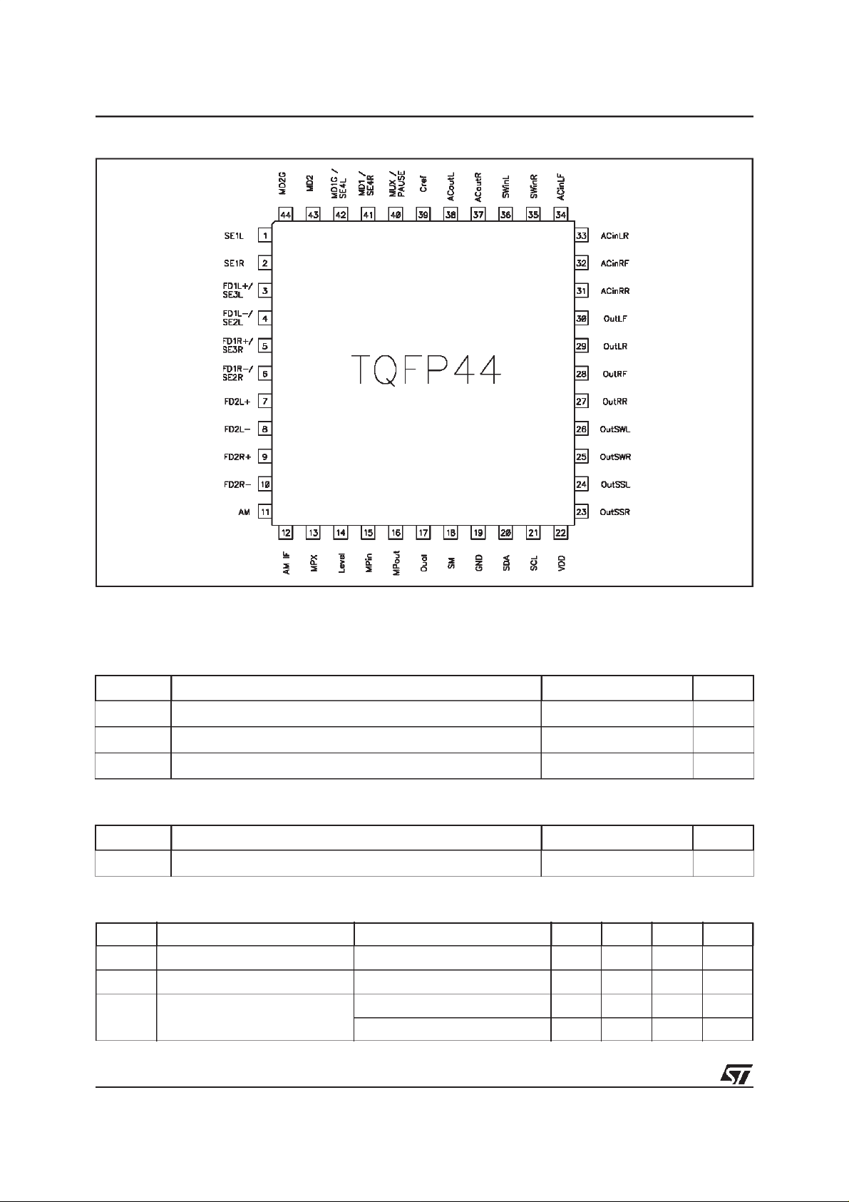
PIN CONNECTION (Top view)
ESD:
All pins are protected against ESD according to the MIL883 standard.
ABSOLUTEMAXIMUM RATINGS
Symbol Parameter Value Unit
T
V
amb
T
stg
Operating Supply Voltage 10.5 V
S
Operating Temperature Range -40 to 85 °C
Storage Temperature Range -55 to +150 °C
THERMAL DATA
Symbol Parameter Value Unit
R
th j-pins
Thermal Resistance Junction-pins max 65 °C/W
SUPPLY
Symbol Parameter Test Condition Min. Typ. Max. Unit
V
SVRR Ripple Rejection @ 1kHz Audioprocessor (allFilters flat) 60 dB
Supply Voltage 7.5 9 10 V
S
I
Supply Current VS=9V 50 mA
S
Stereodecoder + Audioprocessor 55 dB
2/59

BLOCK DIAGRAM
TDA7402
3/59

TDA7402
Audioprocessor Part Features:
Input Multiplexer 2 fully differential CD stereo inputs with programmable attenuation
1 single-ended stereo input
2 differential mono input
1 single-ended mono input
In-Gain 0..15dB, 1dB steps
internal Offset-cancellation (AutoZero)
separate second source-selector
Beep internal Beep with 4 frequencies
Mixing stage Beep, Phone and Navigation mixable to all speaker-outputs
Loudness programmable center frequency and frequency response
15 x 1dB steps
selectable flat-mode (constant attenuation)
Volume 0.5dB attenuator
100dB range
soft-step control with programmable times
Compander dynamic range compression for use with CD
2:1 compression rate
programmable max. gain
Bass 2nd order frequency response
center frequency programmable in 8 steps
DC gain programmable
+ 15 x 1dB steps
Treble 2nd order frequency response
center frequency programmable in 4 steps
+15 x 1dB steps
Voice Bandpass 2nd order butterworth highpass filter with programmable cut-off frequency
2nd order butterworth lowpass filter with programmable cut-off frequency
selectable flat-mode
Speaker 4 independent speaker controls in 1dB steps
control range 95dB
separate Mute
Subwoofer single-ended stereo output
independent stereo level controls in 1dB steps
control range 95dB
separate Mute
Mute Functions direct mute
digitally controlled SoftMute with 4 programmable mute-times
Pause Detector programmable threshold
4/59

TDA7402
ELECTRICAL CHARACTERISTICS
VS= 9V; T
Symbol Parameter Test Condition Min. Typ. Max. Unit
INPUT SELECTOR
=25°C; RL=10kΩ; all gains = 0dB; f = 1kHz; unless otherwise specified
amb
R
V
S
G
IN MIN
G
IN MAX
G
STEP
V
V
offset
Input Resistance all single ended Inputs 70 100 130 kΩ
in
Clipping Level 2.2 2.6 V
CL
Input Separation 80 100 dB
IN
Min. Input Gain -1 0 +1 dB
Max. Input Gain 15 dB
Step Resolution 1 dB
DC Steps Adjacent Gain Steps 1 mV
DC
Remaining offset with AutoZero 0.5 mV
DIFFERENTIAL STEREO INPUTS
R
Input Resistance
in
(see Figure 1)
G
Gain only at true differential input 0 dB
CD
CMRR Common Mode Rejection Ratio V
RMS
to G
G
MIN
MAX
6mV
Differential 70 100 130 kΩ
-6 dB
-12 dB
CM
=1V
@ 1kHz 46 70 dB
RMS
e
Output-Noise @ Speaker-Outputs 20Hz - 20kHz, flat; all stages 0dB 9 µV
NO
DIFFERENTIAL MONO INPUTS
R
Input Impedance Differential 40 56 k
in
CMRR Common Mode Rejection Ratio V
BEEP CONTROL
V
f
Beep
RMS
Beep Level Mix-Gain = 6dB 350 mV
Beep Frequency f
MIXING CONTROL
M
LEVEL
Mixing Ratio Main / Mix-Source -6/-6 dB
V
CM
CM
V
CM
Beep1
f
Beep2
f
Beep1
f
Beep1
=1V
=1V
=1V
@ 10kHz 46 60 dB
RMS
@ 1kHz 40 70 dB
RMS
@ 10kHz 40 60 dB
RMS
600 Hz
780 Hz
1.56 kHz
2.4 kHz
Ω
5/59

TDA7402
ELECTRICAL CHARACTERISTICS
(continued)
Symbol Parameter Test Condition Min. Typ. Max. Unit
G
A
MAX
A
STEP
MULTIPLEXER OUTPUT
R
R
C
V
Max. Gain 15 dB
MAX
Max. Attenuation -79 dB
Attennuation Step 1 dB
1
Output Impedance 225 Ω
OUT
Output Load Resistance 2 k
L
Output Load Capacitance 10 nF
L
DC Voltage Level 4.5 V
DC
LOUDNESS CONTROL
A
A
f
STEP
MAX
Peak
Step Resolution 1 dB
Max. Attenuation 19 dB
Peak Frequency f
P1
f
P2
f
P3
200 Hz
400 Hz
600 Hz
Ω
VOLUME CONTROL
G
A
MAX
A
STEP
E
E
V
Max. Gain 15.5 dB
MAX
Max. Attenuation 79.5 dB
Step Resolution 0.5 dB
Attenuation Set Error G = -20 to +20dB -0.75 0 +0.75 dB
A
Tracking Error 2dB
T
DC Steps Adjacent Attenuation Steps 0.1 3 mV
DC
SOFT MUTE
A
MUTE
T
Mute Attenuation 80 100 dB
Delay Time T1 0.48 ms
D
f
P4
800 Hz
G = -80 to -20dB -4 0 3 dB
From 0dB to G
MIN
0.5 5 mV
T2 0.96 ms
T3 123 ms
T4 324 ms
V
6/59
TH low
Low Threshold forSM-Pin
2
1V
TDA7402
ELECTRICAL CHARACTERISTICS
(continued)
Symbol Parameter Test Condition Min. Typ. Max. Unit
V
TH high
R
V
Notes: 1. If configured as Multiplexer-Output
High Threshold for SM - Pin 2.5 V
Internal pull-up resistor 32 45 58 k
PU
Internal pull-up Voltage 3.3 V
PU
2. The SM-Pin is active low (Mute = 0)
BASS CONTROL
C
RANGE
A
STEP
Control Range +15 dB
Step Resolution 1 dB
Center Frequency f
f
C
C1
f
C2
f
C3
f
C4
f
C5
f
C6
f
C7
60 Hz
70 Hz
80 Hz
90 Hz
100 Hz
130 Hz
150 Hz
Ω
Q
DC
BASS
Quality Factor Q
Bass-DC-Gain DC = off 0 dB
GAIN
TREBLE CONTROL
C
RANGE
A
STEP
Control Range +15 dB
Step Resolution 1 dB
Center Frequency f
f
C
f
C8
1
Q
2
Q
3
Q
4
200 Hz
1
1.25
1.5
2
DC = on 4.4 dB
C1
f
C2
f
C3
f
C4
10 kHz
12.5 kHz
15 kHz
17.5 kHz
7/59
TDA7402
ELECTRICAL CHARACTERISTICS
(continued)
Symbol Parameter Test Condition Min. Typ. Max. Unit
PAUSE DETECTOR
V
Zero Crossing Threshold Window 1 40 mV
TH
1
Window 2 80 mV
Window 3 160 mV
I
DELAY
V
Pull-Up Current 15 25 35 µA
Pause Threshold 3.0 V
THP
SPEAKER ATTENUATORS
R
G
A
MAX
A
STEP
A
MUTE
E
V
Input Impedance 35 50 65 kΩ
in
Max. Gain 15 dB
MAX
Max. Attenuation 79 dB
Step Resolution 1 dB
Output Mute Attenuation 80 90 dB
Attenuation Set Error 2dB
E
DC Steps Adjacent Attenuation Steps 0.1 5 mV
DC
Notes: 1. If configured as Pause-Output
AUDIO OUTPUTS
V
R
CLIP
R
C
V
Clipping Level d = 0.3% 2.2 2.6 V
Output Load Resistance 2 kΩ
L
Output Load Capacitance 10 nF
L
Output Impedance 30 120 W
OUT
DC Voltage Level 4.5 V
DC
VOICE BANDPASS
f
Highpass corner frequency f
HP
HP1
f
HP2
f
HP3
f
HP4
f
HP5
f
HP6
f
HP7
f
HP8
RMS
90 Hz
135 Hz
180 Hz
215 Hz
300 Hz
450 Hz
600 Hz
750 Hz
8/59
TDA7402
ELECTRICAL CHARACTERISTICS
(continued)
Symbol Parameter Test Condition Min. Typ. Max. Unit
f
Lowpass corner frequency f
LP
LP1
f
LP2
3kHz
6kHz
SUBWOOFER ATTENUATORS
R
G
A
ATTN
A
STEP
A
MUTE
E
V
Input Impedance 35 50 65 k
in
Max. Gain 15 dB
MAX
Max. Attenuation 79 dB
Step Resolution 1 dB
Output Mute Attenuation 80 90 dB
Attenuation Set Error 2dB
E
DC Steps Adjacent Attenuation Steps 1 5 mV
DC
SUBWOOFER Lowpass
f
Notes: 1. If programmed as Subwoofer Diff.-Output
DIFFERENTIAL OUTPUTS
Lowpass corner frequency f
LP
1)
LP1
f
LP2
f
LP3
80 Hz
120 Hz
160 Hz
Ω
R
R
C
LMAX
C
DLMAX
V
Offset
R
V
e
load resistance at each output 1V
L
load resistance differential 1V
DL
Capacitive load at each output C
Capacitive load differential C
DC Offset at pins Output muted -10 10 mV
Output Impedance 30 Ω
OUT
DC Voltage Level 4.5 V
DC
Output Noise Output muted 6 µV
NO
COMPANDER
G
max. Compander Gain Vi < -46dB 19 dB
MAX
; ACcoupled; THD=1% 1 k
RMS
; ACcoupled; THD=1% 2 kΩ
2V
RMS
; ACcoupled; THD=1% 2 kΩ
RMS
; ACcoupled; THD=1% 4 k
2V
RMS
at each Output to Ground 10 nF
Lmax
between Output terminals 5 nF
Lmax
Vi < -46dB, Anti-Clip=On 29 dB
Ω
Ω
9/59

TDA7402
ELECTRICAL CHARACTERISTICS
(continued)
Symbol Parameter Test Condition Min. Typ. Max. Unit
V
t
Att
t
Rel
REF
Attack time t
Release time t
Compander Reference Input-
Att1
t
Att2
t
Att3
t
Att4
Rel1
t
Rel2
t
Rel3
t
Rel4
V
REF1
6ms
12 ms
24 ms
49 ms
390 ms
780 ms
1.17 s
1.56 s
0.5 V
Level (equals 0dB)
C
Notes: 1. If programmed as Subwoofer Diff.-Output
Compression Factor Output Signal / Input Signal 0.5
F
V
V
REF2
REF3
1.0 V
2.0 V
GENERAL
RMS
RMS
RMS
e
Output Noise BW = 20Hz - 20kHz
NO
all gains = 0dB single endedinputs
S/N Signal to Noise Ratio all gains = 0dB
flat; V
O
=2V
RMS
bass, treble at +12dB;
a-weighted; V
V
IN
OUT
=1V
=1V
RMS
RMS
d distortion V
12dB
S
E
Channel Separation left/right 100 dB
C
TotalTracking Error AV= 0 to -20dB 0 1 dB
T
= -20 to -60dB 0 2 dB
A
V
output muted
10
3
µV
µV
106 dB
100 dB
= 2.6V
O
RMS
; all stages 0dB 0.005 %
; Bass & Treble =
0.05 %
10/59

TDA7402
1.0 DESCRIPTION OF THE AUDIOPROCESSOR PART
1.1 Input stages
In the basic configuration two full-differential, two mono-differential, one single ended stereo and one singleended mono input are available. In addition a dedicated input for the stereodecoder MPX-signal is present.
Figure 1. Input-stages
Full-differential stereo Input 1 (FD1)
The FD1-input is implemented as a buffered full-differential stereo stage with 100kΩinput-impedance at each
input. The attenuation is programmable in 3 steps from 0 to -12dB in order to adapt the incoming signal level.
A 6dB attenuation is included in the differential stage, the additional 6dBare done by a following resistive divider. This input is also configurable as two single-ended stereo inputs (see pin-out).
Full-differential stereo Input 2 (FD2)
The FD2-input has the same general structure as FD1, but with a programmable attenuation of 0 or 6dB embedded in the differential stage.
11/59

TDA7402
Mono-differential Input 1 (MD1)
The MD1-input is designed as a basic differential stage with 56kΩ input-impedance. This input is configurable
as a single-ended stereo input (see pin-out).
Mono-differential Input 2 (MD2)
The MD2-input has the same topology as MD1, but without the possibility to configure it to single ended.
Single-endedstereo Input (SE1), single-ended mono input (AM) and FM-MPX input
All single ended inputs offer an input impedance of 100kΩ. The AM-pin can be connected by software to the
input of the stereo-decoder in order to use the AM-noiseblanker and AM-High-Cut feature.
1.2 AutoZero
The AutoZero allows a reduction of the number of pins as well as external components by canceling any offset
generated by or before the In-Gain-stage (Please notice that externally generated offsets, e.g. generated
through the leakage current of the coupling capacitors, are not canceled).
The auto-zeroing is started every time the DATA-BYTE 0 is selected and needs max.
To avoidaudible clicks the Audioprocessor is muted before the loudness stage during this time. The AutoZerofeature is only present in the main signal-path.
0.3ms for the alignment.
AutoZero for Stereodecoder-Selection
A special procedure is recommended for selecting the stereodecoder at the main input-selector to guarantee
an optimum offset-cancellation:
(Step 0: SoftMute or Mute the signal-path)
Step 1: Temporary deselect the stereodecoder at all input-selectors
Step 2: Configure the stereodecoder via IIC-Bus
Step 3: Wait 1ms
Step 4: Select the stereodecoder at the main input-selector first
The root cause of this procedure is, that after muting the stereodecoder (Step 1), the internal stereodecoder
filters have to settle in order to perform a proper offset-cancellation.
AutoZero-Remain
In some cases, for example if the µP is executing a refresh cycle of the IIC-Bus-programming, it is not useful
to start a new AutoZero-action because no new source is selected and an undesired mute would appear at the
outputs. For such applications the A619 could be switched in the
dress-byte). If this bit is set to high, the DATABYTE 0 could be loaded without invoking the AutoZero and the
old adjustment-value remains.
AutoZero-Remain-Mode (Bit 6 of the subad-
1.3 Pause Detector / MUX-Output
The pin number 40(Pause/MUX) is configurable for two different functions:
1. During Pause-Detector OFF this pin is used as a mono-output of the maininput-selector. This signal is often
used to drive a level-/equalizer-display on the carradio front-panel.
2. DuringPause-Detector ON the pin isused todefine the time-constant ofthe detector by an externalcapacitor.
The pause-detector is driven by the internal stereodecoder-outputs in order to use pauses in the FM-signal
for alternate-frequency-jumps. If the signal-level of both stereodecoder channels is outside the programmed
voltage-window, the external capacitor is abruptly discharged. Inside the pause-condition the capacitor is
slowly recharged bya constant current of 25µA. The pause information is also available via IIC-Bus (see IICBus programming).
12/59

1.4 Loudness
There are four parameters programmable in the loudness stage:
1.4.1 Attenuation
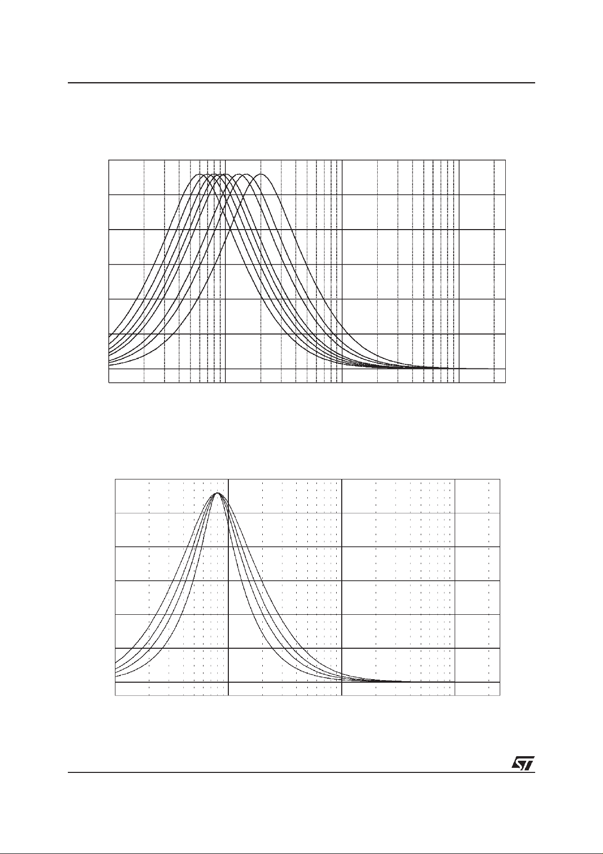
Figure 2 shows the attenuation as a function of frequency at fP= 400Hz
Figure 2. Loudness Attenuation @ fP= 400Hz.
0.0
-5.0
-10.0
dB
-15.0
-20.0
TDA7402
-25.0
10.0 100.0 1.0K 10.0K
Hz
1.4.2 Peak Frequency
Figure 3 shows the four possible peak-frequencies at 200, 400, 600 and 800HzFigure 3: Loudness Center frequencies @ Attn. = 15dB
Figure 3. Loudness Center frequencies @ Attn. = 15dB.
0.0
-5.0
dB
-10.0
-15.0
-20.0
10.0 100.0 1.0K 10.0K
Hz
13/59

TDA7402
1.4.3 Loudness Order
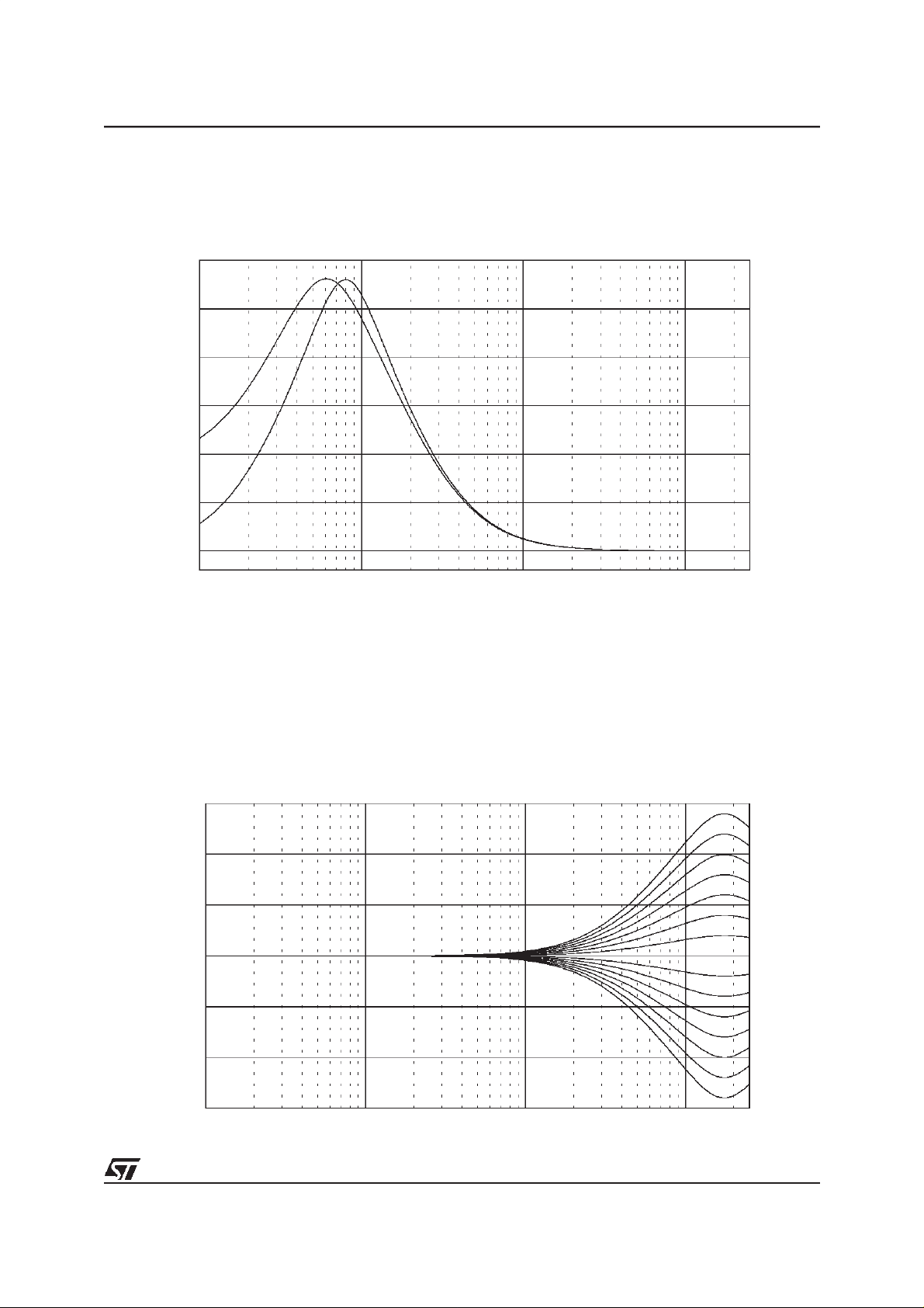
Different shapes of 1st and 2nd-Order Loudness
Figure 4. 1st and 2nd Order Loudness @ Attn. = 15dB, fP=400Hz
0.0
-5.0
dB
-10.0
-15.0
-20.0
10.0 100.0 1.0K 10.0K
1.4.4 Flat Mode
In flat mode the loudness stage works as a 0dB to -19dB attenuator.
Hz
1.5 SoftMute
The digitally controlled SoftMute stage allows muting/demuting the signal with a I2C-bus programmable slope.
The mute process can either be activated by the SoftMute pin or by the I
2
C-bus. This slope is realized in a spe-
cial S-shaped curve to mute slow in the critical regions (see Figure 5).
For timing purposes the Bit0 of the I
2
C-bus output register is setto 1 from the start ofmuting until the end of de-
muting.
Figure 5. Softmute-Timing
Note: Please notice that a started Mute-action is always terminated and could not be interrupted by a change of the mute -signal.
14/59

TDA7402
1.6 SoftStep-Volume
When the volume-level is changed audible clicks could appear at the output. The root cause of those clicks
could either be a DC-Offset before the volume-stage or the sudden change of the envelope of the audiosignal.
With the SoftStep-feature both kinds of clicks could be reduced to a minimum and are no more audible. The
blend-time from one step to the next is programmable in four steps.
Figure 6. SoftStep-Timing
1dB
0.5dB
SS Time
-0.5dB
-1dB
Note: For steps more than 0.5dB theSoftStep mode should bedeactivated because it could generate a hard 1dB stepduring the blend-time.
1.7 Bass
There are four parameters programmable in the bass stage:
1.7.1 Attenuation
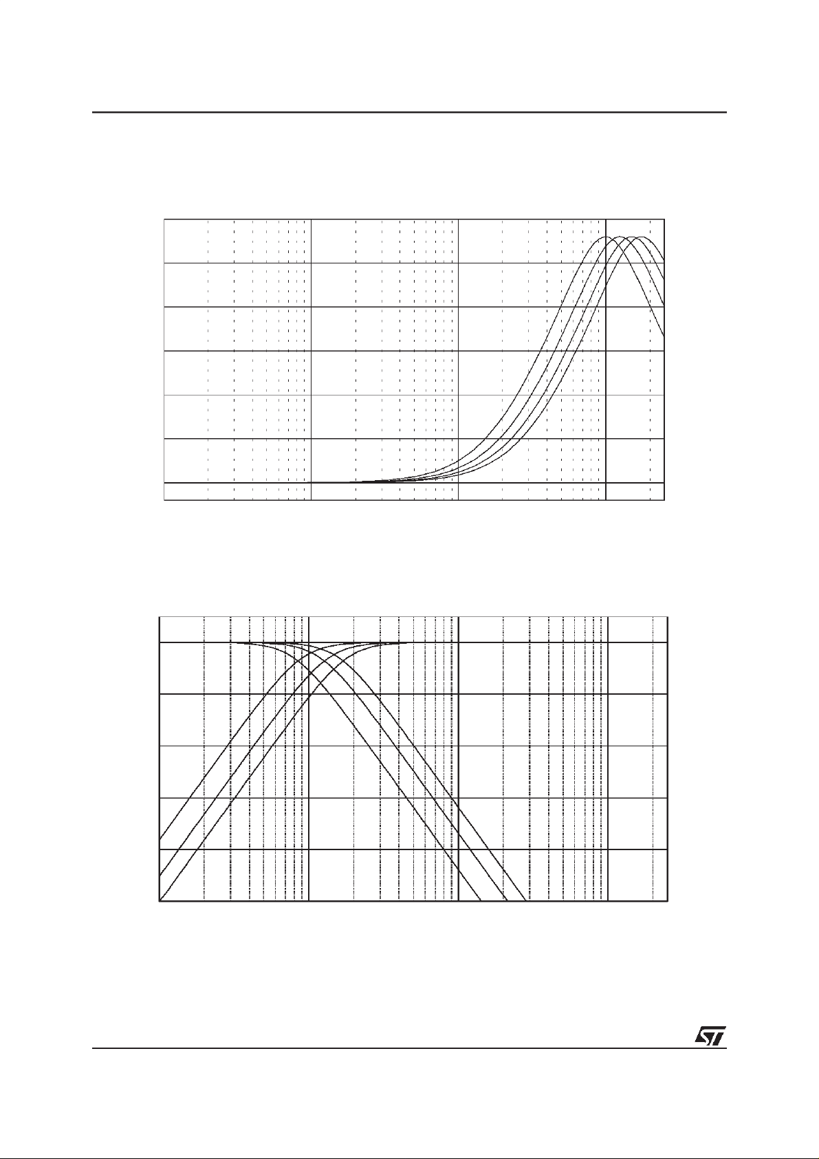
Figure 7 shows the attenuation as a function of frequency at a center frequency of 80Hz.
Figure 7. Bass Control @ fC= 80Hz, Q = 1
15.0
10.0
5.0
dB
0.0
-5.0
-10.0
-15.0
10.0 100.0 1.0K 10.0K
Hz
15/59
TDA7402
1.7.2 Center Frequency
Figure 8 shows the eight possible center frequencies 60, 70, 80, 90, 100, 130, 150 and 200Hz.
Figure 8. Bass center Frequencies @ Gain = 14dB, Q = 1
15.0
12.5
10.0
7.5
dB
5.0
2.5
0.0
10.0 100.0 1.0K 10.0K
Hz
1.7.3 Quality Factors
Figure 9 shows the four possible quality factors 1, 1.25, 1.5 and 2.
Figure 9. Bass Quality factors @ Gain = 14dB, fC= 80Hz
15.0
12.5
10.0
7.5
5.0
2.5
0.0
16/59
10.0 100.0 1.0K 10.0K
TDA7402
1.7.4 DC Mode
In this mode the DC-gainis increased by 4.4dB. In addition the programmed center frequency and quality factor
is decreased by 25% which can be used to reach alternative center frequencies or quality factors.
Figure 10. Bass normal and DC Mode @ Gain = 14dB, fC= 80Hz
15.0
12.5
10.0
7.5
5.0
2.5
0.0
10.0 100.0 1.0K 10.0K
Note: The center frequency, Q and DC-mode can be set fully independently.
1.8 Treble
There are two parameters programmable in the treble stage:
1.8.1 Attenuation
Figure 11 shows the attenuation as a function of frequency at a center frequency of 17.5kHz.
Figure 11. Treble Control @ fC= 17.5kHz
15.0
10.0
5.0
0.0
-5.0
-10.0
-15.0
10.0 100.0 1.0K 10.0K
17/59
TDA7402
1.8.2 Center Frequency
Figure 12 shows the four possible center frequencies 10k, 12.5k, 15k and 17.5kHz.
Figure 12. Treble Center Frequencies @ Gain = 14dB
15.0
12.5
10.0
7.5
5.0
2.5
0.0
10.0 100.0 1.0K 10.0K
1.9 Subwoofer Application
Figure 13. Subwoofer Application with LPF 80/120/160Hz and HPF 90/135/180Hz
0.0
-10.0
-20.0
dB
-30.0
-40.0
-50.0
10.0 100.0 1.0K 10.0K
Hz
Both filters, the lowpass- as well as the highpass-filter, have butterworth characteristic so that their cut-off frequencies are not equal but shifted by the factor 1.125 to get a flat frequency response.
18/59
 Loading...