

.EXCELLENTVERSATILITYIN USE
.HIGHOUTPUTCURRENT (upto 1.5 A)
.
LOW QUIESCENTCURRENT
.LOWREFERENCE VOLTAGE(1.32V)
.
EXCELLENTPARAMETERS STABILITYVERSUSAMBIENTTEMPERATURE
.
START/STOPFUNCTION (TTL levels)
.DUMPPROTECTION
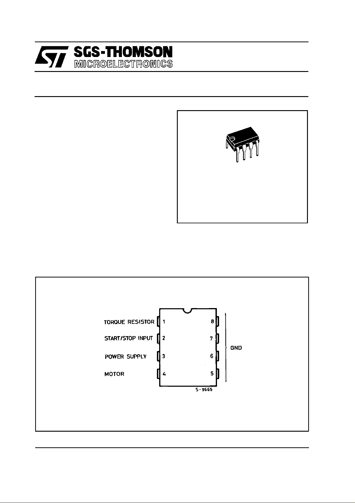
TDA7275A
MOTORSPEED REGULATOR
DES CRIP TION
TheTDA7275Ais a linearintegratedcircuitinminidip plasticpackage.It is intendedfor useasspeed
regulatorforDCmotorsof recordplayers,tape and
cassetterecorders.
Thedumpprotectionmakeitparticularlysuitablefor
car radioapplications.
PIN CONNE CTION (top view)
MINIDIP
(4 + 4 )
ORDERING NUMBER : TDA7275A
May 1997
1/9
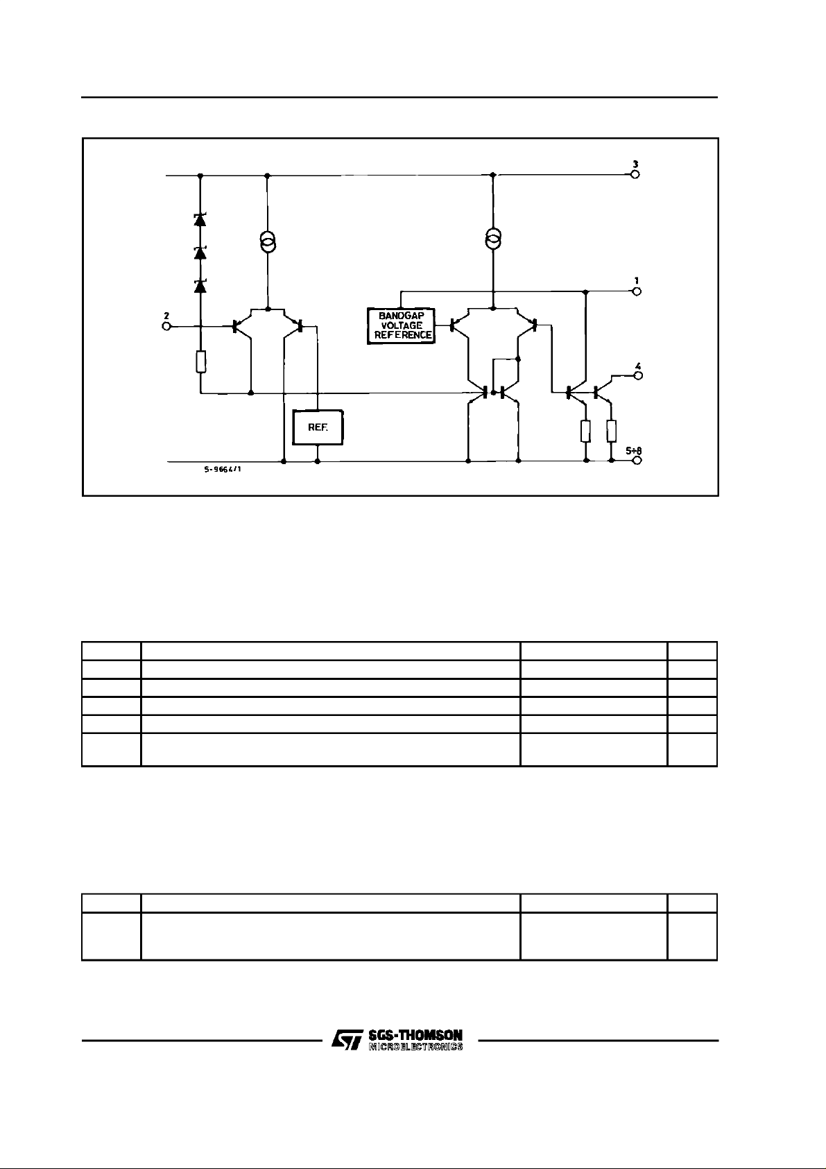
TD A 7275A
SCHEMATI C DIAGRAM
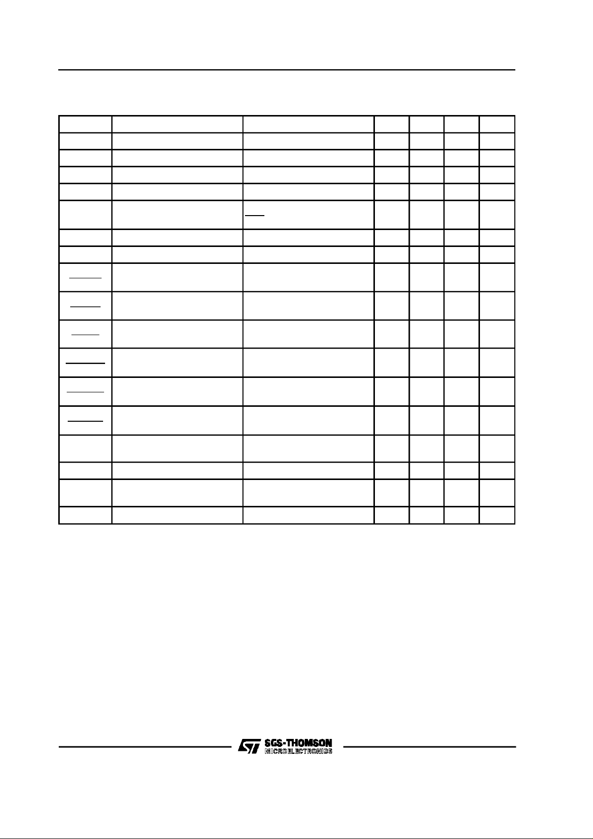
ABSOLUTE MAXIMUM RATINGS
Symbol Parameter Value Unit
Supply Voltage 19 V
V
S
Peak Supply Voltage (for 50ms) 45 V
V
S
Maximum Output Current 1.5 A
I
M
Operating Temperature Range –30 to +85 °C
T
op
Power Dissipation at T
P
tot
at T
amb
pins
=70°C
=70°C
1
4
THERMAL DATA
Symbol Parameter Value Unit
R
thj-amb
R
thj-pins
Thermal Resistance Junction-ambient
Max.
Thermal Resistance Junction -pins Max.
80
20
C/W
°
C/W
°
W
W
2/7
TD A7275A
ELECTRICAL CHARACTERISTICS (Refer to test circuit, VS= 12V, T
=25°C unless otherwise
amb
specified, refer to test circuit)
Symbol Parameter Test Condition Min. Typ. Max. Unit
V
V
I
q+Id
I
I
ms
V
K=I
∆K⁄ ∆V
K
∆K ⁄∆I
K
∆K⁄∆
K
V
∆
ref
V
∆V
ref
V
V
∆
ref
V
V
Supply Voltage Range 8 18 V
S
Reference Voltage IM= 0.1A 1.05 1.22 1.35 V
ref
Total Quiescent Current IM= 0.1mA 2 mA
Quiescent Current IM= 0.1mA 1 mA
d
Starting Motor Current
Saturation Voltage IM= 0.5A 1.7 2 V
4
Reflection coefficient IM= 0.1A 18 20 22 –
M/IT
S
M
T
⁄
V
Line Regulation IM= 0.1A
∆
S
ref
⁄
∆I
Load Regulation IM= 25 to 200mA –0.01 %/mA
M
ref
⁄
T
Temperature Coefficient IM= 0.1A
∆
ref
Motor ”Stop” (Acc. Following
2
V
∆
ref
–50%
=
V
ref
I
= 0.1A
M
= 8 to 16V
V
S
I
= 25 to 200mA –0.05 %/mA
M
= 0.1A
I
M
= –30 to +85°C
T
op
= 8 to 16V
V
S
= –30 to +85°C
T
op
1A
0.5 %/V
0.02 %/°C
0.04 %/V
0.02 %/°C
1V
data or grounded)
I
V
Motor ”Stop” V2 = 1V –0.05 mA
2
Motor ”Run” (Acc. Following
2
data or open)
I
Motor ”Run” V2 = 1.5V –0.1 mA
2
1.5 V
3/7

TD A 7275A
Figure1:Test Circu it .
Figure2:Appl ica t i o n Circuit.
–R
Ttyp.=Ktyp.RMtyp.
if RT>K
minRMmin
instabilitymay accur.
– A diodeacrossthe motorcouldbe necessarywith certainkind of motor.
4/7

TD A7275A
Figure 3
: QuiescentCurrentvs.
Supplyvoltage.
Figure 5 : SpeedVariationvs.
Torque(V
= 12 V).
S
Figure 4 :
SpeedVariationvs.
SupplyVoltage.
5/7

TD A 7275A
MINIDIP PACKAGE MECHANICAL DATA
DIM.
MIN. TYP. MAX. MIN. TYP. MAX.
A 3.3 0.130
a1 0.7 0.028
B 1.39 1.65 0.055 0.065
B1 0.91 1.04 0.036 0.041
b 0.5 0.020
b1 0.38 0.5 0.015 0.020
D 9.8 0.386
E 8.8 0.346
e 2.54 0.100
e3 7.62 0.300
e4 7.62 0.300
F 7.1 0.280
I 4.8 0.189
L 3.3 0.130
Z 0.44 1.6 0.017 0.063
mm inch
6/7

TD A7275A
Information furnished is believed to be accurate and reliable. However, SGS-THOMSON Microelectronics assumes no responsibility for
the consequences of use of such information nor for any infringement of patents or other rights of third parties which may result from its
use. No license is granted by implication or otherwise under any patent or patent rights of SGS-THOMSON Microelectronics. Specification
mentioned in this publication are subject to change without notice. This publication supersedes and replaces all information previously
supplied. SGS-THOMSON Microelectronics products are not authorized for use as critical components in life support devices or systems
without express writtenapproval of SGS-THOMSON Microelectronics.
Australia - Brazil - Canada - China - France - Germany - Hong Kong - Italy - Japan - Korea - Malaysia - Malta - Morocco -
The Netherlands - Singapore - Spain - Sweden - Switzerland - Taiwan - Thailand - United Kingdom - U.S.A.
1997 SGS-THOMSON Microelectronics – Printed in Italy – All Rights Reserved
SGS-THOMSON Microelectronics GROUP OF COMPANIES
7/7
 Loading...