

SGS Thomson Microelectronics STV8203 Datasheet
MULTISTANDARDTV SOUNDDEMODULATOR
.
PERFORMS FM MONO, FM 2 CARRIERS
ANDNICAMRECEPTION
.
B/D/G/H/I/K/K1/K2/L/L’
.
UPTO 500kHzDEVIATIONFM DEMODULA TOR
.
ALL PRE AND POST-PROCESSING INTEGRATEDFILTERS,ALIGNMENTFREE
.
STANDARDRECOGNITIONFLAG
.
SINGLEQUARTZ CRYSTAL
.
I2C BUSCONTROLLED
.
AMAND DOUBLESCARTAUDIO MATRIX
.
STAND-BYWITH THRU MODE
.
SINGLEBIT DACS
.
EASY IMPLEMENTATION OF AUTOSTANDARDMODE
.
ADVANCED OPERATING MODE FOR FULL
CUSTOMIZATION
.
SIFAGC WITHWIDE RANGE
STV8203
PRELIMINARY DATA
SHRINK42
(Plastic Package)
ORDER CODE : STV8203
DESCRIPTION
The STV8203provides all the necessary circuitry
for demodulationof all Nicamand Germanstereo
audiotransmission. It is very suitable forTV applicationsas well as for VCR, Personal Computer or
Set Top Box applications. Different transmission
standardsare automaticallydetectedand demodulated without user intervention. The recovered
audio signals can be made available in analog
form. More, the STV8203integrates an audio matrixwith a THRU modewhen the IC is in stand-by.
Very flexible applications are possible thanks to
smart I
appropriateaudio processingICs.
January 1999
This is advance information on a new product now in developmentor undergoing evaluation. Detailsare subject to change without notice.
2
C program modes and large choice of
TQFP44 (10 x 10 x 1.4mm)
(Full Plastic Quad Flat Pack)
ORDER CODE : STV8203D
1/31
STV8203
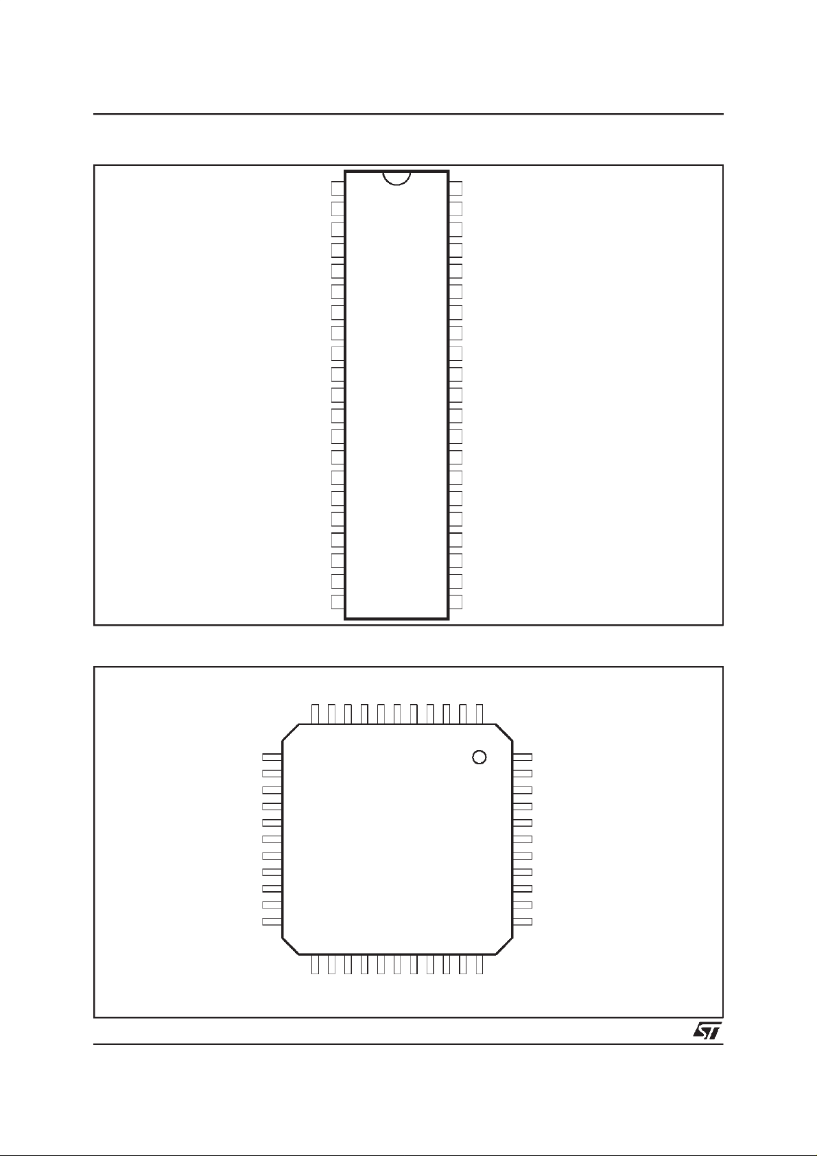
SDIP42PIN CONNECTIONS
CAP5
SIF1
CAP6
SIF2
GND3
MOUT
MIN
CAP8
LIL1
LIR1
GND4
LIL2
LIR2
CAP2
CAP1
AOL1
AOR1
CAP4
AOL2
AOR2
1
2
3
4
5
6
7
8
9
10
11
12
13
14
15
16
17
18
19
20
21 22
CC
42 GND2
41
DV
DD5
REG
40
CAP3
39
NC
38
SCL
37
SDA
36
NOT USED
35
XIN
34
XOUT
33
GND1
32
NC
31
NC
30
NC
29
NC
28
NC
27
NC
26
NC
25
NC
24
RESET
23
CAP7AV
8203-01.EPS
TQFP44PIN CONNECTIONS
MOUT
MIN
CAP8
LIL1
LIR1
GND4
LIL2
LIR2
CAP2
CAP1
AOL1
2/31
GND3
SIF2
SIF1
CAP6
12
13
14
15
16
17
18
19
20
21
22
23 24 25 26 27 28 29 30 31 32 33
AOL2
CAP4
AOR1
AOR2
CAP5
NC
GND2
CC
AV
DD5
DV
CAP7
CAP3
REG
NC
RESET
NC
NC
NC
1234567891011
44
43
42
41
40
39
38
37
36
35
34
NC
SCL
SDA
NOT USED
XIN
XOUT
GND1
NC
NC
NC
NC
NC
8203-02.EPS
PIN LIST
Pin Number
SDIP42 TQFP44
1 7 CAP5 Analog Decoupling for ADC SupplyRegulator Output
2 8 SIF1 Analog Subcarrier 1 Input
3 9 CAP6 Analog Decoupling for Input Amplifier Reference
4 10 SIF2 Analog Subcarrier 2 Input
5 11 GND3 Power Ground for Input Amplifier
6 12 MOUT Analog Mono Audio Output
7 13 MIN Analog Mono Audio Input
8 14 CAP8 Analog ADC VtopDecoupling
9 15 LIL1 Analog Line 1 Left Input (SCART 1)
10 16 LIR1 Analog Line 1 Right Input (SCART 1)
11 17 GND4 Power Audio Ground
12 18 LIL2 Analog Line 2 Left Input (SCART 2)
13 19 LIR2 Analog Line 2 Right Input (SCART 2)
14 20 CAP2 Analog Decoupling forAudio Matrix
15 21 CAP1 Analog Decoupling forBandgap Reference
16 22 AOL1 Analog Line 1 Left Output (SCART 1)
17 23 AOR1 Analog Line 1 Right Output (SCART 1)
18 24 CAP4 Analog Audio Matrix V
19 25 AOL2 Analog Line 2 Left Output (SCART 2)
20 26 AOR2 Analog Line 2 Right Output (SCART 2)
- 27 NC - Not Connected
21 28 AV
22 29 CAP7 Analog Decoupling forDigital Regulator Output
23 30 RESET Input Power On Reset
24 31 NC - Not Connected
25 32 NC - Not Connected
26 33 NC - Not Connected
27 34 NC - Not Connected
28 35 NC - Not Connected
29 36 NC - Not Connected
30 37 NC - Not Connected
31 38 NC - Not Connected
32 39 GND1 Power Digital Ground
33 40 XOUT Analog Crystal Oscillator Output
34 41 XIN Analog Crystal OscillatorInput
35 42 Not used Input To be connected to ground
36 43 SDA Bi-directional I
37 44 SCL Input I
- 1 NC - NotConnected
38 2 NC - Not Connected
39 3 CAP3 Analog Decoupling for Digital 3V (regulator output)
40 4 REG Analog Base Drive for External Regulator Transistor
41 5 DV
42 6 GND2 Power Digital Ground
Name Type Function
(5V)
DD
CC
DD5
Power Audio Matrix Supply
2
C SerialData
2
C SerialClock
Power 5V Supply
STV8203
8203-01.TBL
3/31
STV8203
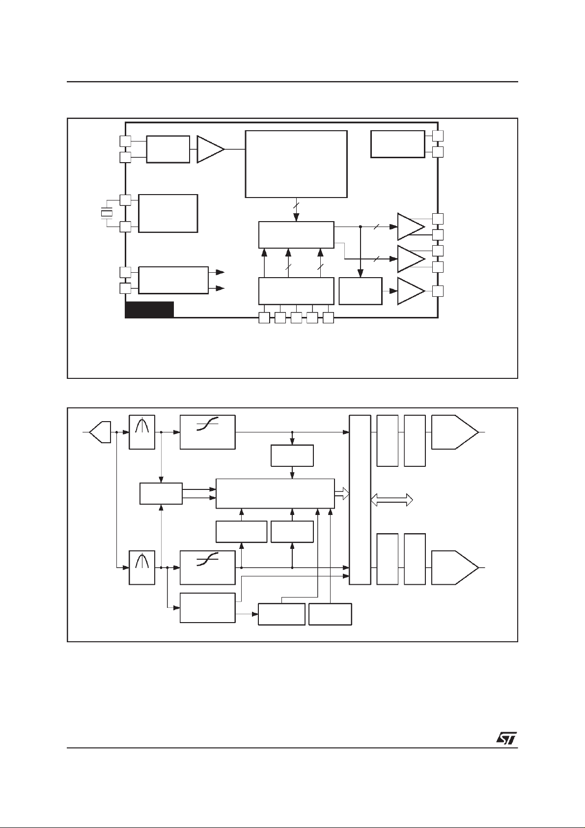
BLOCKDIAGRAM
SIF1
SIF2
ANALOG
SWITCH
AGC
Sub
IN
DEMODULATOR CORE *
XTAL
DV
AV
DD5
CC
CRYSTAL
OSCILLATOR
POWER SUPPLY
REGULATORS
Digital
Analog
STV8203
* See Demodulator Core Block Diagram
DEMODULATORCORE BLOCKDIAGRAM
Sub
ADC
IN
BAND
PASS
FM
DISCRIMINATOR
FM / NICAM
2
AUDIO MATRIX
22
PRE-SCALING
MONO IN
SCART1 IN L
SCART1 IN R
NOISE*
ESTIMATION
SCART2 IN L
L1, R1
(L1 + R1)/2
SCART2 IN R
2
C BUS
I
INTERFACE
2
2V
2
2V
1V
SIGNAL
SHAPING
RMS
RMS
RMS
PRE-SCALING
SDA
SCL
SCART1 OUT L
SCART1 OUT R
SCART2 OUT L
SCART2 OUT R
MONO OUT
ONE BIT
SIGMA
DELTA
DAC
8203-03.EPS
Channel 1
* Data also available throught I
4/31
LEVEL *
ESTIMATOR
BAND
PASS
DISCRIMINATOR
2
C Bus
FM
NICAM QPSK
AND
DECODER
SOUND STANDARD MANAGEMENT
IDENTIFICATION,
CHANNEL CONTROL, MUTE, ...
PILOT *
RECOGNITION
NOISE*
ESTIMATION
QPSK LOCK *
DETECTION
BIT ERROR
RATE *
DIGITAL CHANNEL MATRIX AND AUTOSWITCH
SIGNAL
SHAPING
2
I
C Bus
ONE BIT
SIGMA
DELTA
PRE-SCALING
DAC
Channel 2
8203-04.EPS
FUNCTIONAL DESCRIPTION
Ascanbe seen fromthe blockdiagram,theinputto
the demodulatorsection is selectablefrom one of
twoI.F.sourcesviathe I
2
Cbus.Theselectedsignal
is then passed through an AGC block, having a
range of 28dB, before being digitised in the
ADCunit.Asinglequartzcrystal(suggestedvalue:
between24.712MHzand 27MHz)is usedforthe all
thedigitalprocessing,includingdemodulation,identification, control, filtering. This has the advantage
ofa singleclocksignalsourceforthewholeICwhich
eliminates problems of multiple clock. The single
clock canbe chosento minimize interferencein the
TVIF andRF stagesof the tuner system.
Thedemodulatorsystemcan identifyand demodulateallthestandarddescribedintheTable1. Theresult of the recognition is flagged up to the host
system via the I
2
C buscommunicationsystem.
In the case of NICAM transmissions, in the event
of a failure of the received signal or a degradation
ofthe bit error rate (BER)belowa prescribedlevel,
thesystem will automaticallydefault to the reserve
soundtransmission on mono FM or AM.
For FM demodulation, the discriminator can normallyhandlesignalshaving250kHzdeviation.This
covers all European standards, and ensure an
optimizedcompromise for thesignal to noiseratio
inonehand,andovermodulationintheotherhand.
However, it is possible to extand the deviation
rangeupto 500kHz(I
2
Cprogrammable)in orderto
coverrequests of some broadcasters.
Fully automatic standard recognition and setting
canbe achieveusing simple routines.
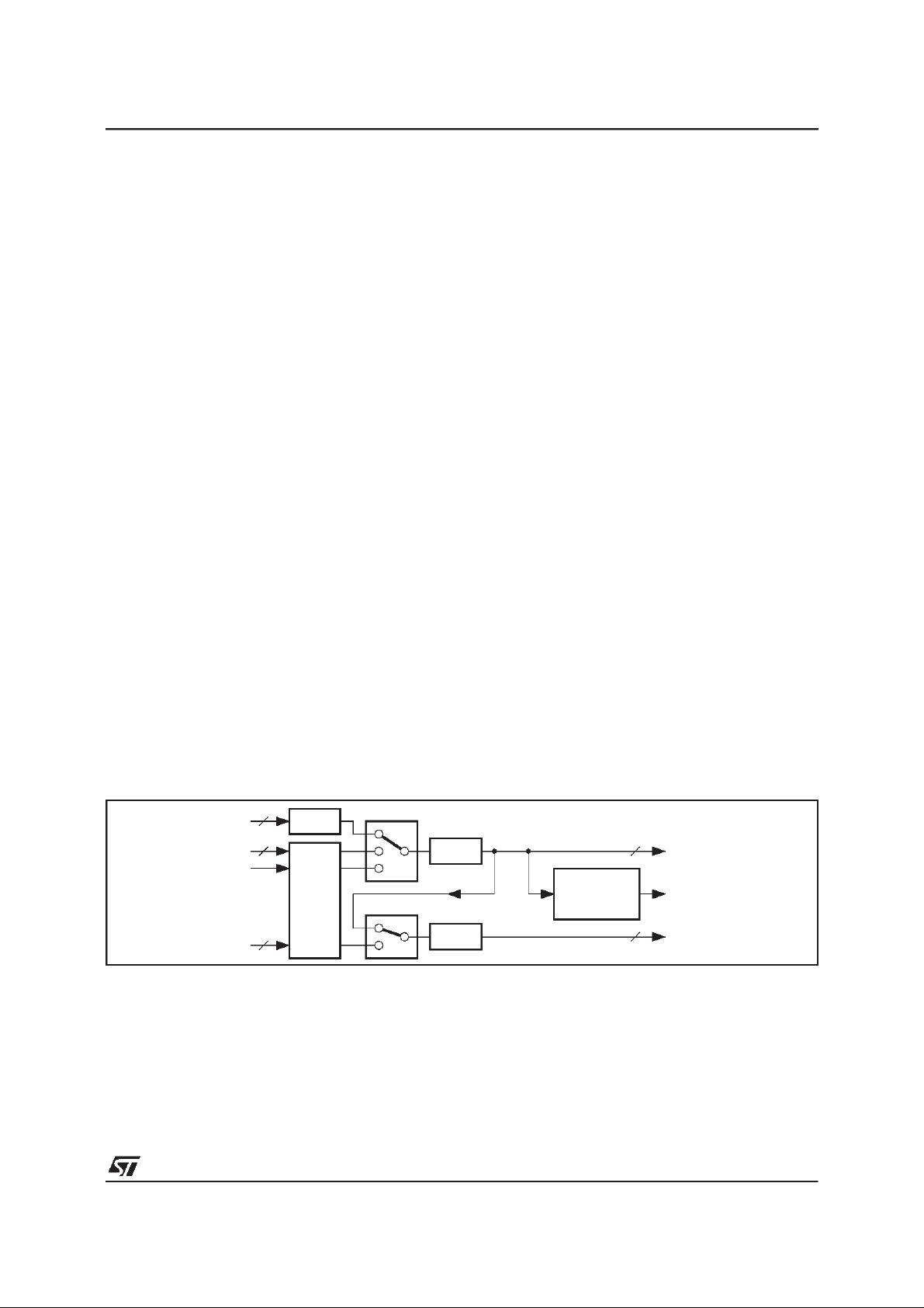
Figure1 : AudioMatrix
2
DAC
LI2(SCART2)
MIN
LI1(SCART1)
MUTE
2
S1
GAIN
± 6dB
2
S2
Appropriate de-emphasis networks in the digital
domain are applied to the resulting demodulated
signals (50µs, J17), followed by dematrixing if required. The digital datastream is then passed
through2 x 16bits DACs before the audio matrix.
All thisfirst section is workingat 3.3Vthanks to an
integratedvoltageregulator.In stand-bymode,the
voltage regulator pulls the voltage down to zero,
ensuringno power dissipationin thispart.
An audio matrix allows the selection of inputs appliedontheoutputsSCART1,SCART2andMONO
accordingto the diagram shown in Figure1.
The ”MOUT”outputs eitherthe signal L1, or R1 or
(L1+R1)/2.Thisallowstorecordtheselectedchannel in monomode, for exampleon thelinear channel of a VCR simultanously with the stereo mode.
Maximumoutput swingis 1V
RMS
.
The audio matrixsection has its own power supply
regulator,allowing to keep this part working even
when the rest is instand-bymode. Thisachievesa
”THRU” mode from input ”SCART1” to output
”SCART2”andinput”SCART2”tooutput”SCART1”.
The maximumoutput swing of both SCART1 and
SCART2is 2V
RMS
.
Remark : Circuit operationis possible with only a
single5V supply.In thiscase, the AV
CC
is connectedto 5V.Maximumoutput swingis then
limitedto 1V
anda 6dBattenuationis automat-
RMS
ically added to the DAC output. In that case, the
resistorshown as R2 =39Ωin theApplicationDiagram (between Pin 8 and Pin 21) must be replace
by a short circuit to avoid clipping.
MUTE
MUTE
L1/R1
L1,R1,
(L1 + R1)/2
SELECTOR
L2/R2
2
2
AO1(SCART1)
MOUT
AO2(SCART2)
STV8203
supplypin
8203-05.EPS
5/31
STV8203
FUNCTIONAL DESCRIPTION(continued)
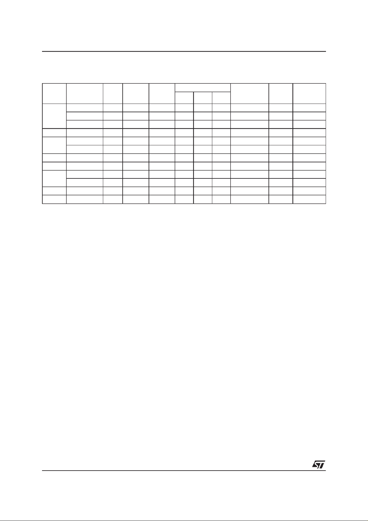
Table1 :DemodulatedTV SoundNorms
Type
System Sound Type
FM mono 5.5
B/G
FM/NICAM 5.5 5.850 27 50 80 J17 40
FM 2 carriers A2 5.5 5.742 27 50 80 50µs 54.6875
B/H FM/NICAM 5.5 5.850 27 50 80 J17 40
FM mono 6.5
D/K
FM/NICAM 6.5 5.850 27 50 80 J17 40
D/K1 FM 2 carriers A2* 6.5 6.258 50µs 54.6875
D/K2 FM 2 carriers 6.5 6.742 50µs 54.6875
FM/NICAM 6.0 6.552 27 50 80 J17 100
I
FM mono 6.0 50µs
L NICAM 6.5 (1) 5.850 J17 40
M/N FM mono 4.5 (2) 15 25 50 (2)
Notes : 1. STV8203 performs only limitedAM demodulation. Report to Application Note.
2. 50µs only, instead of 75µs.
Name
Carrier 1
(kHz)
Carrier 2
(kHz)
FM Deviation (kHz)
Nom. Max. Over
Deemphasis Roll-off
Frequency
Pilot
(kHz)
6/31
USINGSTV8203
1 - Hardware
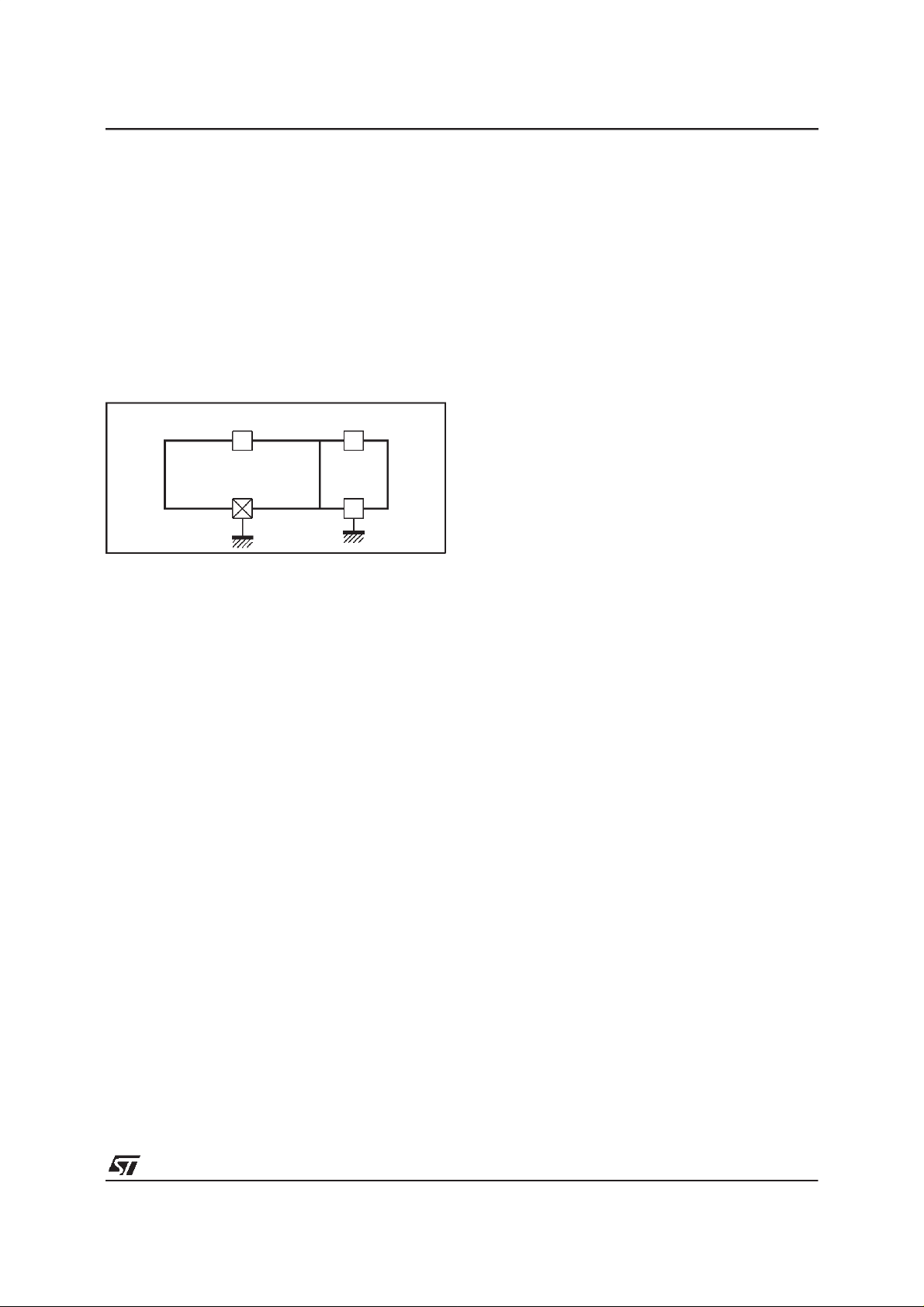
1.a - PowerSupplies (see Figure 2)
TheIC is usingtwo mainpower supplies:
-DV
supplies all the digital part V
DD5
Nom.
=5V.
This power supply can be switched-off in standby mode.
-AV
suppliestheaudio matrixpart : ifV
CC
Nom.
then the output voltage swing on outputpins can
reach2V
RMS
,ifV
swing on outputpins can reach 1V
=5Vthentheoutputvoltage
Nom.
RMS
.
Figure2
DV
DD5
41
DEMODULATION
ANDCONTROLPART
Pins5-32-42
GND
AV
CC
21
AUDIO
MATRIX
11
GND
=8V
STV8203
between stereo or mono signals in the playback
modein case of marginalnoise conditions.
1.d - Stand-by
Stand-bywith THRU mode : theanalogpartof the
device has its own power supply (AV
thispart to keepworkingevenwhenthedigitalpart,
powered by the 5V power supply (DV
stand-by.
In this case, the audio matrix is put in a special
setting:
- LIL1 to AOL2,
- LIR1 to AOR2,
- LIL2 to AOL1,
- LIR2 to AOR1,
- input gain = 0dB.
This allows to achieve a ”THRU” mode from
SCART1 input to SCART2 output and SCART2
input to SCART1 output, providing a copy facility
fromSCARTINto SCARTOUT.
8203-06.EPS
) allowing
CC
DD5
), is in
1.b- Sound Subcarrier Filters
Sound demodulation and decoding are very easy
withthisdeviceprovidingallthenecessaryfunctions
for that purpose, including the channel filters.
TheseFIRbase-bandfiltersgivethe bestselectivity
ofthedesiredchannelandprovidesinNICAMmode
thecorrectcosine roll-off response.
This implies that no external filters are required
(exceptmay be a simplehigh-passfilter,ifthe saw
filters and sound IF demodulators used in the applicationcreate picture interferences).
Thefilterscan beautomaticallyset forB/G/H/I/L/L’
standards.They can alsobe easily tuned through
2
C for M, D, K, K1.
I
1.c- AudioMatrix
The mono output (MOUT) can output L1, R1 or
(L1+R1)/2 signal.A typicalapplicationis the possibilityto recorda selectedchannelin monomodeon
thelineartrackofa VCRseparatelyfromtherecordingofthestereosignal,providingthefacilitytoselect
2 - Software
Twomodes of operationare available:
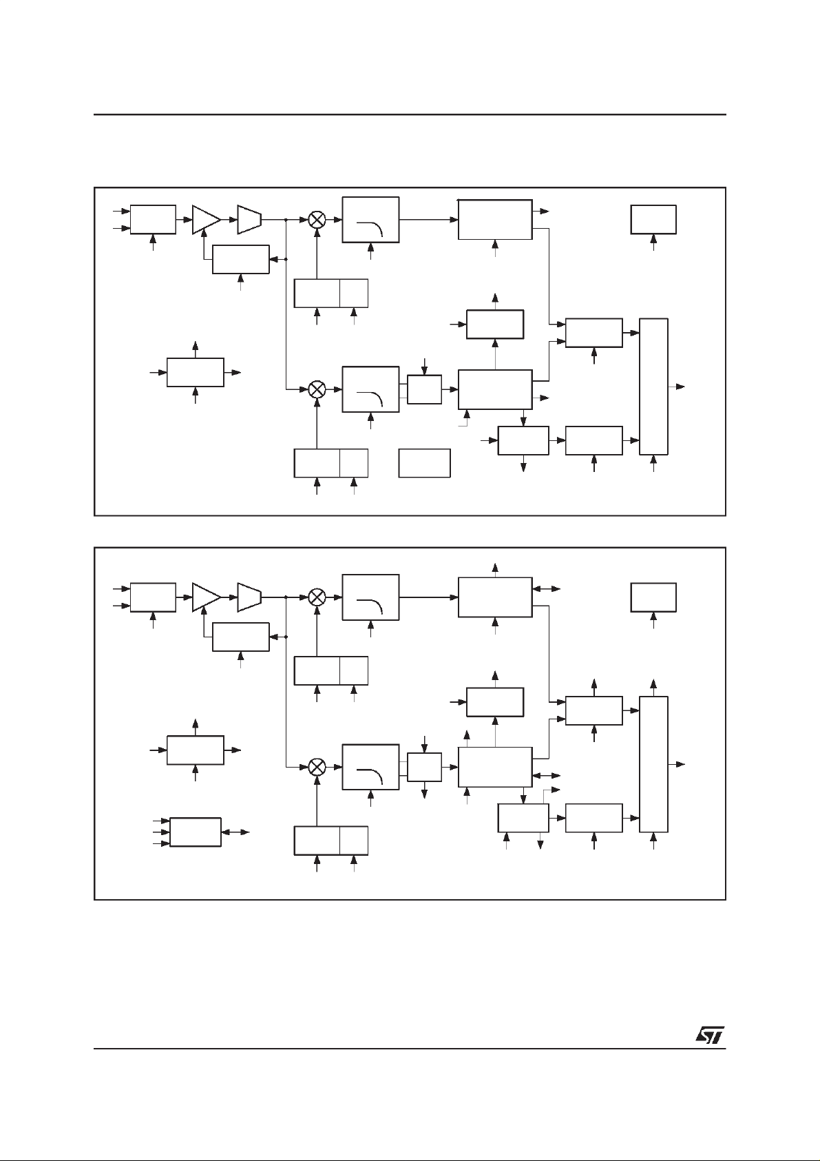
2.a - OptimizedProgram Mode
Fourstandardshavedefaultsettingstoredin order
to allow a very easy programmation. Only some
registersmay have to be programmed(these registersare shownin bold in theFigure3)but inmost
cases, the reset values will be sufficient. In Figure3, CTLand STATrepresentregisterswhich are
controlledby the ”standardprocessor”.These registers are located between address 23Hex and
3CHex in thecomplete list of registers.
2.b - AdvancedOperationMode
In that mode, all the read/write registers (as mentionned in the complete list) can be programmed
manuallyand changedfromtheir reset values.
The additionnal registers accessible in this mode
are shown in bold in Figure 4. This mode can be
selectedby putting the bits [3:0] of AO-CONTROL
registerto 0.
7/31
STV8203
USINGSTV8203 (continued)
Figure3 : Optimized Program Mode
IF1
IF2
INPUT
SWITCH
PRE-LINE-IN
STAT
AGC
AO-STAT0
AO-STAT1
AO-STAT2
AUTO
STANDARD
AO-CONTROL
AO-TIMEOUT
ADC
LEVEL
DETECTOR
AGCC
AGCS
CTL
CH1
DCO
COARSE
CTL
CH2
DCO
COARSE
Figure4 : AdvancedOperation Mode
IF1
IF2
INPUT
SWITCH
AGC
ADC
CH1
CHANNEL
FILTERFIR1
CTL
DCO
FINE
CTL
CHANNEL
FILTERFIR2
CTL
DCO
FINE
CTLCTL
CHANNEL
FILTERFIR1
ZWEITON
CTL
AGC
INPUT
CETH2
SQTH2
CLOCK
CONTROL
PLL
DEMODULATOR
FM
CETH1 - SQTH1
STAT
ZWEITON
DETECTOR
PLL
DEMODULATOR
FM/QPSK
NICON
STAT(2)
PLL
DEMODULATOR
FM
NICAM
DECODER
STAT
STAT
STAT
CRF1
FM
PRESCALE
PRE-FM
NICAM
PRESCALE
PRE-NICAM
AUDIO
MATRIX
PRE-LINE-IN
AUD-MX-CNT
DE-EMPHASIS
SWITCHDE-MATRIX
CTL
AUDIO
MATRIX
To
DAC’s
8203-07.EPS
PRE-LINE-IN
STAT
(1),(2) or (3)
FFFIXL
FFFIXH
FCFIX
(1)
Bitsin AO-STAT0
(2) Bitsin AO-STAT1
(3) Bitsin AO-STAT2
AO-STAT0
AO-STAT1
AO-STAT2
AUTO
STANDARD
AO-CONTROL
AO-TIMEOUT
CLOCK
CONTROL
LEVEL
DETECTOR
AGCC
AGCS
CTL
SRF
DCO
CH2
DCO
DCO
FINE
FILTERFIR2
DCO
FINE
COARSE
COFQ1 FIFQ1
COARSE
COFQ2 FIFQ2
FIR1CO-7
CHANNEL
FIR2CO-7
ZWEITON
IAGCR
IAGCC
AGC
INPUT
IAGCS
CETH1- SQTH1
ACOEFF1 - BCOEFF1
STAT(2)
ZWEITON
DETECTOR
STAT(2)
PLL
DEMODULATOR
FM/QPSK
CETH2
SQTH2
ACOEFF2
BCOEFF2
SCOEFF
NICAM
DECODER
NICON ERR-
COUNT
PRE-LINE-IN
AUD-MX-CNT
FMDC1/2 STAT(1)
FM
PRESCALE
PRE-FM
CRF2
STAT(3)
NICAM
PRESCALE
PRE-NICAM
DE-EMPHASIS
SWITCHDE-MATRIX
STD-CT-IIS
To
DAC’s
8203-08.EPS
8/31
USINGSTV8203 (continued)
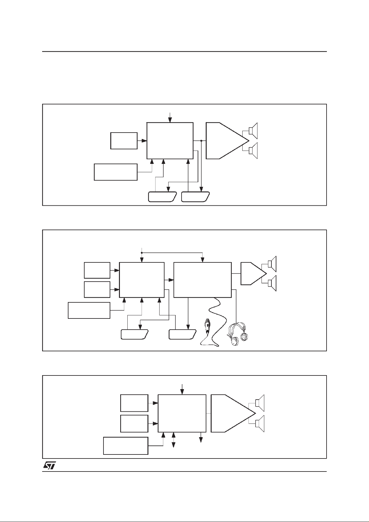
3 - Example of Applications
3.a - VeryLow Cost TVApplication
Figure5
2
C Control
I
STV8203
TUNER1
QSS I.F.
AM
DEMODULATOR
3.b- High-End TV Application
Figure6
TUNER 1
QSS I.F.
TUNER 2
QSS I.F.
AM
DEMODULATOR
MULTISTANDARD
MULTISTANDARD
2
C Control
I
SOUND
PROCESSOR
STV8203
SOUND
PROCESSOR
STV8203
SCART1 SCART2
AUDIO
PROCESSOR
SURROUND/KARAOKE
SRS
TDA7466
AUDIO
AMPLIFIER
TDA7495
2x7W
8203-09.EPS
R
2 x 25W
L
3.c - TVApplication in PC
Figure7
DEMODULATOR
SCART1 SCART2
I2C Control
TUNER1
QSSI.F.
TUNER2
QSSI.F.
MULTISTANDARD
SOUND
PROCESSOR
STV8203
AM
I2S Bus
Analog
AudioOut
8203-10.EPS
AUDIO
AMPLIFIER
TDA7495
8203-11.EPS
9/31
STV8203
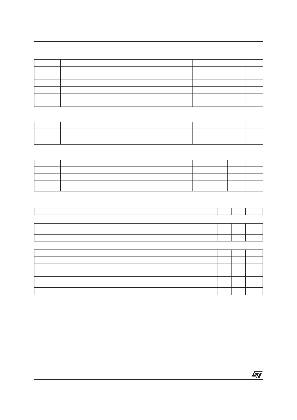
ABSOLUTE MAXIMUMRATINGS
Symbol Parameter Value Unit
AV
DD5
DV
DD5
AV
CC
P
tot
T
oper
T
stg
THERMAL DATA
Symbol Parameter Value Unit
R
th (j-p)
RECOMMENDEDOPERATING CONDITIONS
Symbol Parameter Min. Typ. Max. Unit
AV
DD5
DV
DD5
AV
CC
Analog Supply Voltage 7 V
Digital Supply Voltage 7 V
Scart Interface Supply Voltage 9.5 V
Power Total Dissipation 0.8 W
Operating Temperature 0, +70
Storage Temperature -20, +150
Junction to PinsThermal Resistance Max.
Analog V
Digital V
DD
DD
Audio Interface Supply for 2V
for 1V
RMS
RMS
SDIP42
TQFP44
outputs
outputs
4.75 5.0 5.25 V
4.75 5.0 5.25 V
7.6
4.75
55
68
8.0
5.0
8.4
5.25
o
C
o
C
°C/W
°C/W
V
V
8203-02.TBL
8203-03.TBL
8203-04.TBL
ELECTRICAL CHARACTERISTICS (T
=25oC, unless otherwise specified)
amb
Symbol Parameter Test Conditions Min. Typ. Max. Unit
GENERAL
I
I
Input Currenton AV
AIN
DIN
CC
AVCC=5V
=8V
AV
CC
DV
= 5V 120 mA
DD5
58
75
IF INPUTS
R
C
Input Resistance 6 kΩ
IN
Input Capacitance 10 pF
IN
SWISO Switch Isolation f = 10MHz 40 dB
SIF FR Input Frequency Range For FM demodulation 4 8 MHz
V
IN (Min.)
V
IN (Max.)
Minimum InputLevel
Maximum Input Level
25
630
mV
mV
AGC AGC Range 28 dB
mA
mA
RMS
RMS
8203-05.TBL
10/31
 Loading...