

SGS Thomson Microelectronics STV300NH02L Datasheet
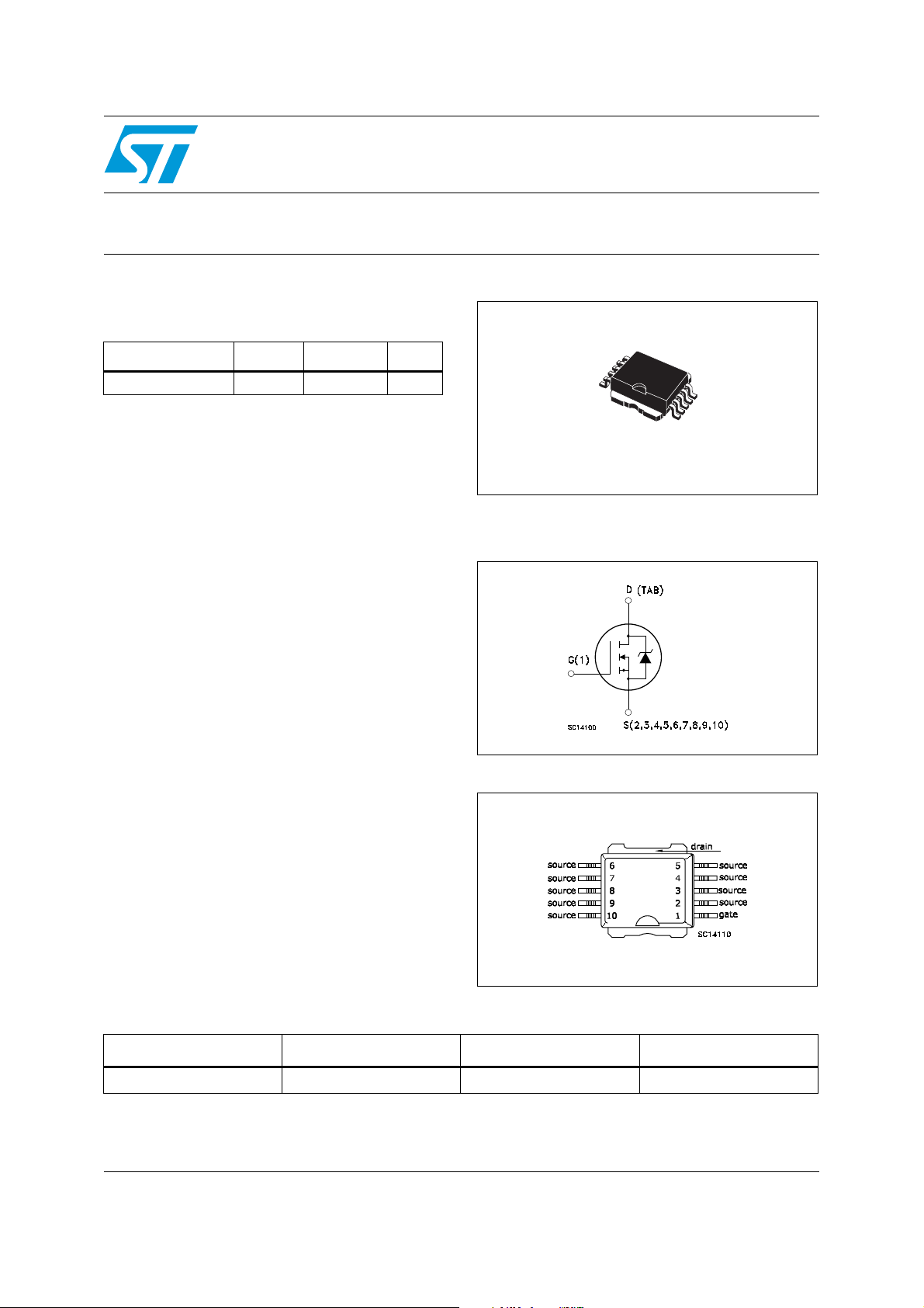
N-channel 24V - 0.8mΩ - 280A - PowerSO-10
Features
Typ e V
STV300NH02L 24V 0.001Ω 280A
■ R
DS(on)*Qg
■ Conduction losses reduced
■ Low profile, very low parasitic inductance
■ Switching losses reduced
industry’s benchmark
DSS
Applications
■ Switching applications
–OR-ing
■ Specially designed and optimized for high
efficiency DC/DC converters.
R
DS(on)
STV300NH02L
STripFET™ Power MOSFET
I
D
10
1
PowerSO-10
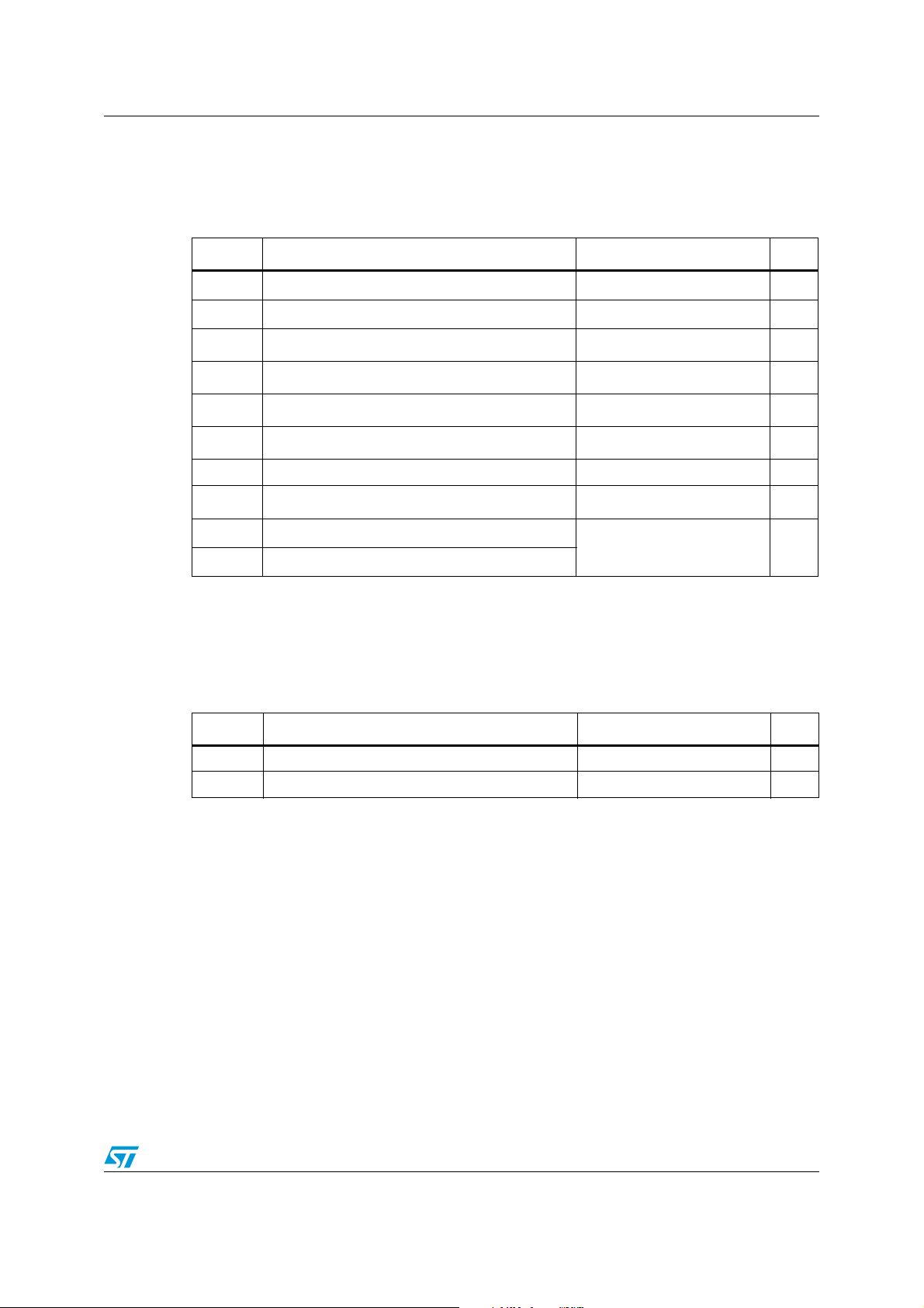
Figure 1. Internal schematic diagram
Description
This product utilizes the latest advanced design
rules of ST’s proprietary STripFET™ technology.
This is suitable for high current OR-ing
application.
Figure 2. Connection diagram (top view)
Table 1. Device summary
Order code Marking Package Packaging
STV300NH02L 300NH02L PowerSO-10 Tape & reel
September 2007 Rev 2 1/12
www.st.com
12

Content STV300NH02L
Content
1 Electrical ratings . . . . . . . . . . . . . . . . . . . . . . . . . . . . . . . . . . . . . . . . . . . . 3
2 Electrical characteristics . . . . . . . . . . . . . . . . . . . . . . . . . . . . . . . . . . . . . 4
2.1 Electrical characteristics (curves) . . . . . . . . . . . . . . . . . . . . . . . . . . . . . 5
3 Test circuits . . . . . . . . . . . . . . . . . . . . . . . . . . . . . . . . . . . . . . . . . . . . . . 8
4 Package mechanical data . . . . . . . . . . . . . . . . . . . . . . . . . . . . . . . . . . . . . 9
5 Revision history . . . . . . . . . . . . . . . . . . . . . . . . . . . . . . . . . . . . . . . . . . . 11
2/12
STV300NH02L Electrical ratings
1 Electrical ratings
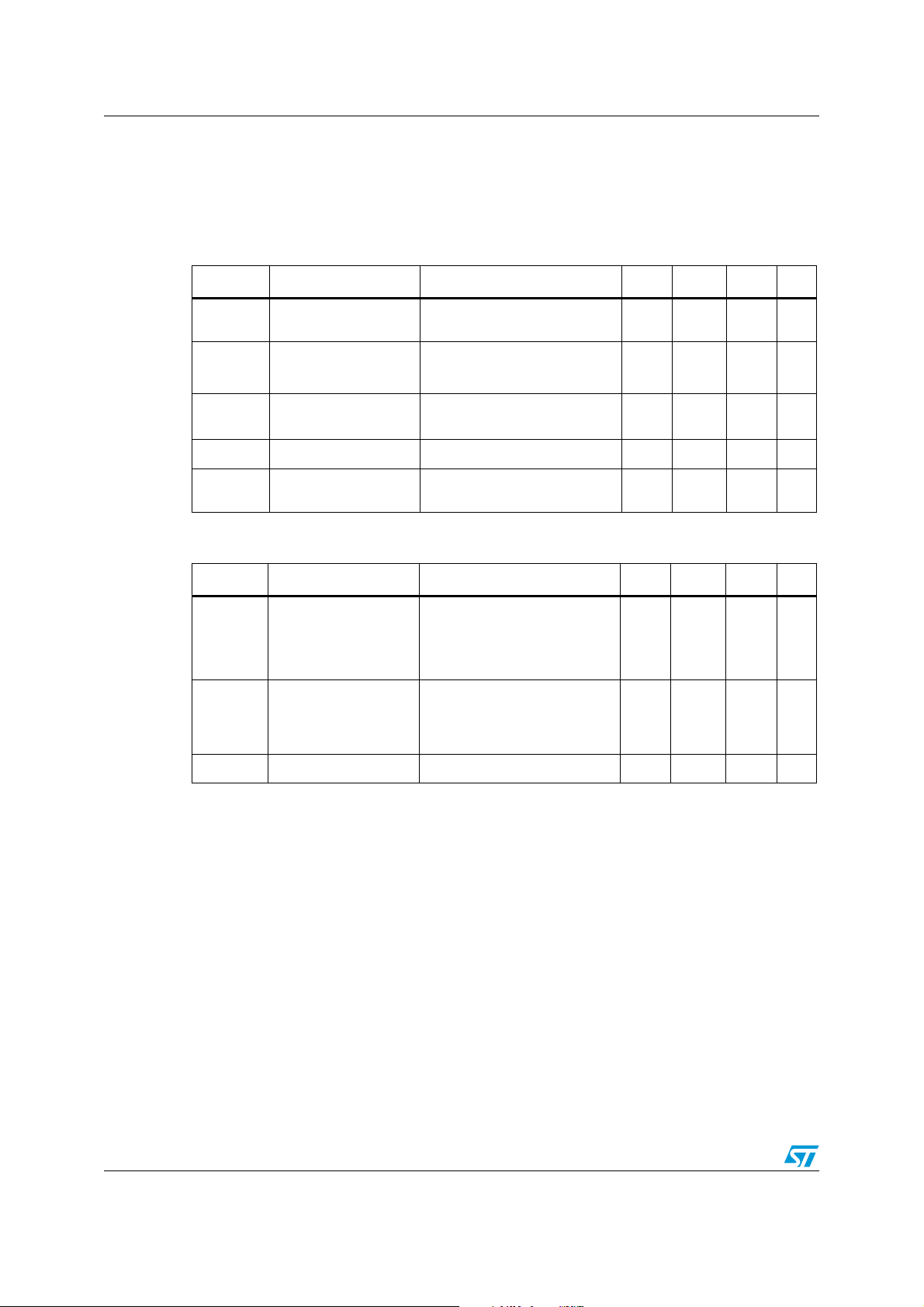
Table 2. Absolute maximum ratings
Symbol Parameter Value Unit
P
V
V
I
I
I
DM
TOT
D
D
Drain-source voltage (vgs = 0)
DS
Gate-source voltage ± 20 V
GS
(1)
Drain current (continuous) at TC = 25°C
(1)
Drain current (continuous) at TC = 100°C
(2)
Drain current (pulsed) 1120 A
(3)
Total dissipation at TC = 25°C
24 V
280 A
200 A
300 W
Derating factor 2 W/°C
(4)
E
AS
T
1. This value is limited by package
2. Pulse with limited by safe operating area
3. This value is rated according to Rthj-c
4. Starting Tj = 25°C, ID = 60A, VDD = 20V
Single pulse avalanche energy 1.6 J
Storage temperature
stg
T
Operating junction temperature
j
-55 to 175 °C
Table 3. Thermal data
Symbol Parameter Value Unit
Rthj-case Thermal resistance junction-case max 0.5 °C/W
Rthj-amb Thermal resistance junction-ambient max 50 °C/W
3/12
Electrical characteristics STV300NH02L
2 Electrical characteristics
(Tcase =25°C unless otherwise specified)
Table 4. On /off states
Symbol Parameter Test conditions Min. Typ. Max. Unit
V
(BR)DSS
I
DSS
I
GSS
V
GS(th)
R
DS(on)
Drain-source
breakdown voltage
Zero gate voltage
drain current (VGS = 0)
Gate body leakage
current (V
DS
= 0)
Gate threshold voltage
Static drain-source on
resistance
= 1mA, VGS= 0
I
D
V
= Max rating,
DS
V
= Max rating, Tc=125°C
DS
= ± 20V
V
DS
V
= VGS, ID = 250µA
DS
VGS= 10V, ID= 80A
24 V
1
10µAµA
±100 nA
11.52V
0.8 1 mΩ
Table 5. Dynamic
Symbol Parameter Test conditions Min. Typ. Max. Unit
C
C
C
Q
Q
Q
R
Input capacitance
iss
Output capacitance
oss
Reverse transfer
rss
capacitance
g
Total gate charge
Gate-source charge
gs
Gate-drain charge
gd
Gate input resistance
G
= 15V, f = 1 MHz, VGS =0
V
DS
= 12V, ID= 120A,
V
DD
= 10V
V
GS
(see Figure 15)
= 0V, f = 1 MHz, VGS =0
V
DS
7055
3251
307
109
30
26
4.4 Ω
pF
pF
pF
nC
nC
nC
4/12
 Loading...