

BUS CONTROLLED PAL/SECAM/NTSC TV PROCESSOR
.
I2C BUS CONTROL OF ALL FUNCTIONS
.
INTEGRATED FILTERS
(TRAP,BANDPASS, CLOCHE)
.
INTEGRATED LUMINANCEDELAYLINE
.
PAL/SECAM/NTSCCHROMADEMODULATORS
.
AUTOMATIC CUT-OFF CURRENTLOOP
.
TWORGB INPUTS
.
SVHSSWITCH
.
TWOPLLs HORIZONTALDEFLECTION
.
VERTICALCOUNT DOWN
.
VERYFEW EXTERNALCOMPONENTS
DESCRIPTION
The STV2118Bis a fully bus controlled IC for TV
luma, chroma and deflectionprocessing.
Used withSTV8224 (PIF/SIF/switches), TDA1771
or TDA8174(framebooster),STV2180(delayline),
it allows to design a PAL/SECAM/NTSC
(BGDKILMN) set with very few external components and no adjustment.
STV2118B
SHRINK42
(Plastic Package)
ORDER CODE : STV2118B
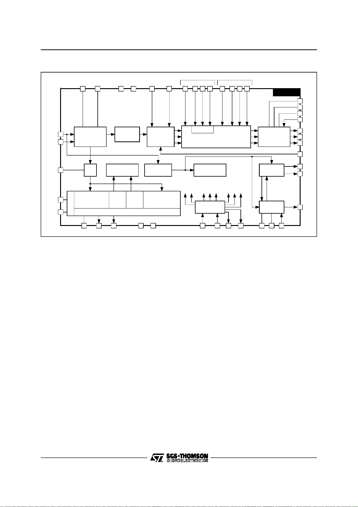
PINCONNECTIONS
CHROMA/SCANNING GROUND
ACC CONTROLCAPACITOR
CLOCHE FILTER TUNING
VOLUME ANDMUTE CONTROL VOLTAGE
IF STANDARD AND SWITCH S ELECTION
EXTERNAL BLUE INPUT
EXTERNAL GREEN INPUT
EXTERNAL RGB INSERTION
CVBS OR LUMINANCE INPUT
3.58MHz XTAL
4.43MHz XTAL
CHROMA LOOP FILTER
DATAWIRE I
CLOCK WIRE I
OSD GREEN INPUT
OS D RGB INSERTION
EXTERNAL RED INPUT
2
C BUS
2
C BUS
FILTER TUNING
OS D BLUE INPUT
OS D RED INPUT
ACC
SDA
SCL
VOL
SWI
1
2
3
4
5
6
7
8
9
10
11
12
13
14
15
16
17
18
19
20
21 22
GND2 V
CXTL2
CXTL1
CLPF
FTUN1
FTUN2
BOSD
GOSD
ROSD
FBOSD
BEXT
GEXT
REXT
FBEXT
Y/CVBS
GND1
42
41
40
39
38
37
36
35
34
33
32
31
30
29
28
27
26
25
24
23
CC2
BYO
RYO
RYI
BYI
LFB/SC
HOUT
VOUT
VAMP
SLPF
SXTL
BCL
ICAT
RO
GO
BO
CR
CB
CG
CHR/SVHS
V
CC1
CHROMA/SCANNING/BUS SUP P LY
B-Y OUTPUT
R-Y OUTPUT
R-Y INPUT
B-Y INPUT
LINE FLYBACK INPUT/SANDCASTLE OUTPUT
HORIZONTAL OUTP UT
VERTICAL OUTPUT
AMPLITUDE CONTROL VOLTAGE
SCANNING LOOP FILTER
503kHz CERAMIC
BEAM CURRENT LIMITER
CATHODE CURRENT MEASUREMENT
RED OUTPUT
GREEN OUTPUT
BLUE OUTPUT
RED CUT-OFF CAPACITOR
BLUE CUT-OFF CAPACITOR
GREEN CUT-OFF CAPACITOR
CHROMINANCE INPUT/SVHS SELECTION
VIDEO SUP PLYBUS/VIDEO GROUND
2118B-01.EPS
June 1996
1/25
STV2118B
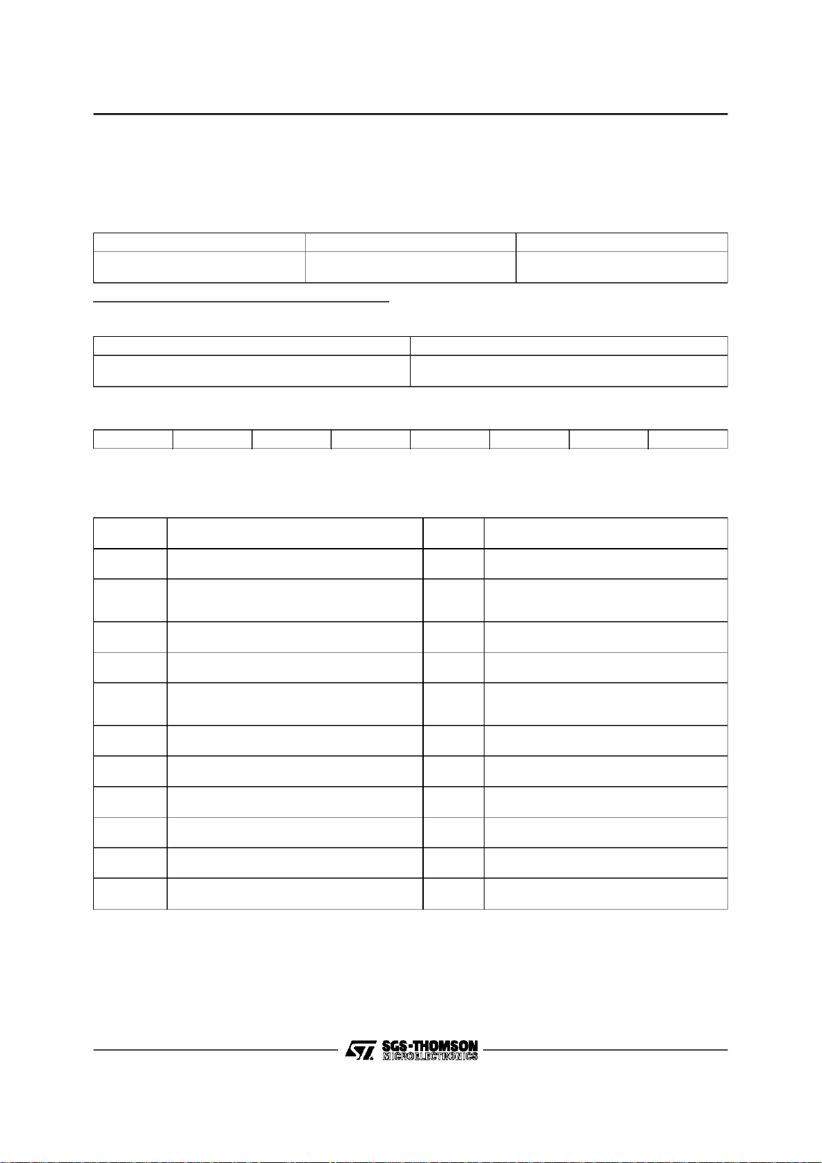
BLOCK DIAGRAM
FILTER
TUNING
89
2
3
FILTER TUNING
TRAP BANDP ASS
CLOCHE
SVHS SWITCH
CHR
ACC5
SECAM
DEMODULATOR S
PLL
Y/CVBS
CHR
ACC
CXTAL2
CXTAL1
20
23
CLOCHE
TUNING
Y
IDENTIFICATION
DELAYLINE INTERFACE
V
V
CC1
22 42 19 18 17 1639 38
DELAY
LINE
SHARP NESS
STANDARD
SECAM
KILLER
NTSC
KILLER
CC2
PAL/
R-Y B-Y
SATURATION
BRIGHTNE SS
SEPARATOR
DEMODULATOR S
MATRIX
CONTRAST
SYNC
PAL/NTSC
EXTERNAL OS D
FB RGBFBRG B
Contras t
IDENTIFICATION
SHARP
HUE
DECODER
15 14 13 12
RGB SWITCHES
VIDEO
BRIG
SAT
CONT
BUS
STD
DRIVE
CUT-OFF
STV2118B
BLANKING
AUTO CUT-OFF
BLACK&WHITE
CONTRO L
FRAME
SCANNING
LINE
SCANNING
25
CB
CG
24
26
CR
30
ICAT
29
R
28
G
27
B
BCL
31
VOUT
35
34
VAMP
36
HOUT
44041
21 1 373332
GND2 SWI VOLCLPF R-Y B-Y
GND1
6 7 11 10
SDA SCL
SXTAL SLPF
LFB/SC
2118B-02.EPS
2/25

FUNCTIONAL DESCRIPTION
1 - DEFLECTION CIRCUIT
Note : [X,Y] : line number referred to the internal
line counternumbering
- Fullyintegratedsynch. separator,withalowpass
filter, a blacklevelalignmentof the Y/CVBSinput,
a slicing level at 2/3,1/3 of the sync. pulseamplitude.
- Frame sync. pulse locked on 2 f
frequency to
H
perfect interlace.
- 500kHzVCOwithan externalceramicresonator.
- Twophase locked loops
• thefirst PLLlocksthe VCO on thevideo signal
frequency,
• thesecondPLLcompensatestheline transistor
storage time.
- Three time constants for the first PLL.
• thelong timeconstantisused for normal opera-
tion
• the short time constant is automatically used
during the frameretraceand in searchmode of
VCR when theframe pulse is outside[258,264]
and [309,314].
• verylongtimeconstantwhenno video recogni-
tion
Timeconstants in normaloperation
(automatic selection of time constants) :
50Hzinput signal :
- short time constant : [306, 21]
- longtime constant : the restof the field
60Hzinput signal :
- short time constant : [0, 16]
- longtime constant : the restof the field
• inhibitionof the first PLL :
the first locked loop is opened from line 309 to
line 4.5(or314)in50Hzmode.It is openedfrom
line 258 to line 5.5 (or 264) in 60Hz mode.
• thetime constantsvaluesare chosenbymeans
of external components.
• possibility to force the short time constant
through the bus.
• possibility to force the very long time constant
through the bus.
- Video identification : coincidence detector between the line synchro top and a line frequency
windowfromthefirst PLL.Thevideoidentification
statusisavailableinthe outputregisterof the I
2
C
bus decoder.
- Generation of burst gate pulses and line frequency signals from the first PLL to drive the
STV2118B
chroma and video circuits. The burst gate pulse
is alsosent to the sandcastlegenerator.
- Framesynchrowindow :
[248, 352] catching
- Field frequency selectionwindows :
[248, 288] 60Hz mode selection if two
consecutive frame pulses occur
insidethiswindow,otherwise50Hz
mode selection.
[288, 352] 50Hz mode selection window
- frameblanking pulse :
from line 0 to 21 in50Hzmode
from line 0 to 16 in60Hzmode
- Verticaloutput pulse is 10.5 lineslong.
- Horizontal output pulse : 28µs line pulse on an
open collectoroutput;
- Start up circuit: the horizontaloutput is at a high
level when V
shutting down, horizontal pulses are disabled
when V
CC
- Soft-startcircuit : the duty cycleof the horizontal
output is78 %(Thigh/(Thigh+TLow))whenV
is lower than (0.75 x V
time.
During the falling time, a 78% duty cycle HOUT
pulse is provided when V
(0.60 x V
CC2
- Possibilityto disable the horizontal output pulse
through the bus (forcea high level onHOUT).
- Horizontalposition adjustmentcontrolled by bus.
- Buscontrolledoutputvoltagetoadjustthevertical
amplitude;this voltagepermitsto adjusttheslope
of the verticalsawtoothgeneratedbythe external
frame booster.
- Buscontrolledvertical position; thehigh levelof
the vertical pulse permits to adjust the vertical
position.
- Bus controlled 4/3-16/9 selection : the low level
of theverticalpulseis0.1Vwhen16/9isselected,
2V when4/3 is selected.
- Combined flyback input and sandcastle output
(Pin 37).
Two thresholds on LFB/SCO Pin : The lowest
threshold(0.7V) permits to extractthelineblanking pulse; the highest threshold (2V) permits to
extract the line pulse for PLL2.
The sandcastlesignalat Pin 37is usedto control
the externalbaseband chromadelay line.
increases from 0 to 6.8V. On
CC
isbelow 6.2V.
), during the rising
CC2
CC1
).
CC1
is lower than
3/25

STV2118B
FUNCTIONAL DESCRIPTION (continued)
2 - FILTERS
- Integrated trap filter :
f
−3dB
1
f
f
o
−3dB
−
f
o
Q =
Centerfrequency : - 4.43MHz,
- 4.25MHz, for SECAM
- Integratedchromabandpass :
Q = 3.5
Centerfrequency: 4.43MHz, 3.58MHz
- Integratedcloche filter for SECAM:
Q=16
Centerfrequency: 4.286MHz
- Integrateddelay line :
Bandwidth = 8MHz
- Integratedlow passfilter fordeflection part.
- All filtersare tunedwith a referencephaselocked
loop.
The PLL consists of a lowpass filter, a phase
comparator,a loop filter (an external capacitor).
The reference signal is the continuous carrier
wave from the VCO (4.43MHz or 3.58MHz). The
PLLadjusts the center frequency of the lowpass
so that it is equal to the reference signal. The
tuningvoltageof thePLLisusedtoadjustallother
filters.Theclochefilteris finetuned witha second
PLLoperating during frame retrace.
3 - VIDEO CIRCUIT
- 2 RGB inputs : RGB (OSD) input has priority
againstthe RGBext. Maximum contraston RGB
(OSD).-12dB range contrast control on RGBext.
Q = 1.7 at sharp.min
Q = 3.0 at sharp. max
3.58MHzfor PAL, NTSC
(f
= 3MHz ; -20dB
-3dB
rejection between 4.1MHz
and 4.4MHz)
Possib ility to disable the RGBext insertio n
through the bus.
- Oversizeblanking capabilityon FB(OSD)(Pin15)
input. The RGB ouputs will be blankedwhen the
voltageon Pin15 willexceedthe secondthreshold at 1.9V (blanking threshold) : the whole field
is blankedbutnotthe insertedcut-off pulses.The
OSDinsertion thresholdis 0.7V.
- Automaticcut-off current loop : 2V cut-off range.
Sequential cut-off current measurement during
the three lines after the frame blanking signal.
Leakage current measurementduring the frame
blanking,memorizationon an internal capacitor.
- Possibility to force through the bus the inserted
cut-off pulses on lines 23/24/25(CCIR) in 50Hz
and 60Hzmode.
- Warmup detector.
- Beamcurrent limiter DC voltageinput.
The beam current limiter control voltage will act
on contrast first, then the brightness will be decreasedwhen contrastattenuationreaches-5dB.
- Bus control of the red, green and blue channel
gain (White pointadjustment)
- Buscontrolofthe red andgreen DC levels (black
point adjustment)
- PAL and SECAM matrix, specific NTSC matrix
when demodulationangles are (0
o
,104o).
- Switch-offof the trap filterin SVHSmode.
- Buscontrolledcontraston luminance
(20dBrange)
- Buscontrolledsaturation (50dB range)
- Bus controlled brightness : 40% range at maximum contrast.
- Bus controlled sharpness (peaking); sharpness
active in PAL/NTSC standardonly.
- Noisecoring function on sharpness.
4/25

FUNCTIONAL DESCRIPTION (continued)
4 - CHROMACIRCUIT
4.1 - PAL/SECAM/NTSC Decoders
- SVHS inputs ; bus controlledSVHS mode.
- 30dB range ACC
- Use of an exter nal base ba nd d elay l ine
(STV2180recommended)
- Automaticstandardidentification,with possibility
to force the standard throughthe bus.
4.2 - PAL/NTSC Decoders
- ACC doneby peakdetector on synchronousdemodulationof the burst
- Fullyintegrated killer functions.
- VCO using two standard crystals: 4.43MHzand
3.58MHz. One crystal is internally selected dependingon the standard selection.
XTALSPECIFICATION:
Frequency:
4.433619MHz(PAL/SECAM)
3.579545MHz(NTSC M)
3.575611MHz(PAL M)
3.582056MHz(PALN)
Vibrationmode : Fondamental,seriesresonance
(no serial capacitor)
Motionalcapacity : 13fF ±3fF
Resonanceresistance: < 70Ω
Shunt capacitance : < 7pF
Spuriousresponse : No resonanceat 3*f
o
-0
and ±90odemodulationangles for PAL
o
-(0
,90o)or(0o,104o) = demodulation angles for
NTSC. The selection of 90
o
or 104ois made
±3kHz
o
through the bus.
- Buscontrol Hueadjustment in NTSC mode.
4.3 - SECAM Decoder
- ACC
- Fullyintegrated killer
- Twointegrateddiscriminatorswith two PLL
- Integrateddeemphasis
STV2118B
4.4 - Standard Identification
- Sequentialidentification.
- 3 identification sequences : XTAL1 (4.43MHz)
mode to identify either PAL or NTSC, XTAL2
(3.58MHz)mode to identifyeither PALor NTSC,
SECAM mode(XTAL1 selection).
- PAL/NTSCpriority
- the SECAM mode is locked after two identified
SECAM sequences
- the SECAM mode can beselected in50Hz only
- Blanking of the (R-Y) and B-Y) outputs during
color search mode.
5 - OTHER FUNCTIONS : IF CONTROLS
5.1 - Volume Control and Mute
Thevolumecontrol voltagerangeon Pin 10isfrom
0.5V to 5V. A low voltage on Pin 10 (below 0.2V)
will mute the FM demodulator of the IF circuit
STV8224. It will put the volume at the minimum
level and thus there will be no sound either in TV
mode or SCARTmode.
The volume controlvoltageand the mute level are
controlledby thebus.
5.2- IFStandard and TV/SCART ModeSelection
The selection of IF standard (positive or negative
visionmodulation)and theTV/SCARTmode is controlledbythe bus.Theselectionisconvertedinfour
voltageson Pin 21.
The lowest voltage selects the TV mode and the
NEGATIVE vision modulation.
The highest voltage (open collector output with
internal pull-upresistorto V
mode and the NEGATIVE visionmodulation.
The two other intermediate voltages select either
TV mode and POSITIVE vision modulation or
SCARTmode and POSITIVE visionmodulation.
) selects the SCART
CC
5/25
STV2118B
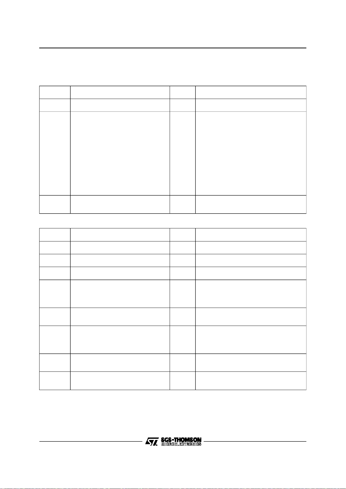
I2C BUS SPECIFICATION
GeneralComments
SlaveAddress : 8A (HEX) (1000101X)
WRITEMODE DATA FORMAT
Slave Address Register Address Data
1000 1010
(8A)
The not used bits indata byte must be put to ”0”.
READ MODE DATAFORMAT
Slave Address Data
1000 1011
(8B)
MSB on the left, LSBon theRight.
MSB LSB
XXXXXXXX
X :not significant bit - S : significant bit
Input Signals (Write Mode)
VIDEO
Address
Dec (HEX)
0 (00) Contrast 5 XXX0 0000 = -20dB
0 (00) External Fast Blanking Enable 1 XXSX XXXX
1 (01) Saturation 6 XX00 0000 = -44dB
2 (02) Brightness 5 XXX0 0000 = -20%
2 (02) RGB Outputs Blanking 1 XXSX XXXX
3 (03) Red Drive Adjust(white point red adjust) 6 XX00 0000 = -6dB
4 (04) Red Cut-off Adjust 6 XX00 0000 = +150mV
5 (05) Green Drive Adjust (white point green adjust) 6 XX00 0000 = -6dB
6 (06) Green Cut-off Adjust 6 XX00 0000 = +150mV
7 (07) Blue Drive Adjust (white pointblue adjust) 6 XX00 0000 = -6dB
8 (08) Sharpness 3 XXXX X000 = Peaking Min.
Description
XXS SSSS
(from 00 to 11HEX)
Data
(Bits)
XXSS SSSS
(6 significant bits Max.)
SSSS SSSS
(8 significant bits)
Comments
XXX1 1111 = 0dB
0 = RGBext insertion enable
1 = RGBext insertion disable
XX11 1111 = +6dB
XXX1 1111 = +20%
0 = Normal mode
1 = Blanking active
XX11 1111 = 0dB
XX11 1111 = -150mV
XX11 1111 = 0dB
XX11 1111 = -150mV
XX11 1111 = 0dB
XXXX X111 = Peaking Max.
6/25
I2C BUS SPECIFICATION (continued)
Input Signals (Write Mode) (continued)
CHROMA
Address
Dec (HEX)
Description
9 (09) Hue 6 XX00 0000 = -45
10 (0A) StandardSelection 4 XXXX SSSS
10 (0A) SVHS Selection 1 XXXS XXXX
Data
(Bits)
XX11 1111 = +45
0000 = PAL/XTAL1 (4.43MHz)
0001 = PAL/XTAL2 (3.58MHz)
0010 = NTSC/XTAL1/90
0011 = NTSC/XTAL2/90
0100 = SECAM/XTAL1
1010 = NTSC/XTAL1/104
1011 = NTSC/XTAL2/104
011X = Auto/90
111X = Auto/104
0101 = Not allowed
1000 = Not allowed
1001 = Not allowed
1100 = Not allowed
1101 = Not allowed
0 = No SVHS (CVBS mode)
1 = SVHS mode
STV2118B
Comments
o
o
o
o
o
o
o
o
DEFLECTION
Address
Dec (HEX)
Description
11 (0B) HorizontalShift 6 XX00 0000 = -2.5µs
12 (0C) Vertical Amplitude 6 XX00 0000 = 1.2V
13 (0D) Vertical Position 3 XXXX X000 = 3.8V
13 (0D) 50/60Hz Selection 2 XXXS SXXX
13 (0D) Horizontal Output (HOUT) Safety 1 XXSX XXXX
14 (0E) PLL1 Time Constant 2 XXXX XXSS
14 (0E) Interlace 1 XXXX XSXX
14 (0E) 4/3 16/9 Selection 1 XXXX SXXX
Data
(Bits)
XX11 1111 = +2.5µs
XX11 1111 = 6.2V
XXXX X111 = 6.3V
00 = Auto
01 = 60Hz
10 = 50Hz
11 = Auto
0 = Normal mode
1 = HOUT disabled (high level)
00 = Normal mode (Auto)
01 = Short time constant
10 = Very long time constant
11 = PLL1 inhibition(open loop)
0 = Interlace
1 = DE-Interlace
0 = 4/3 (V
1 = 16/9 (V
OUT-Low
OUT-Low
Comments
= 2V)
= 0.1V)
7/25
STV2118B
I2C BUS SPECIFICATION (continued)
Input Signals (Write Mode) (continued)
OTHERS
Address
Dec (HEX)
15 (0F) Volume 6 XX00 0000 = 0.5V
16 (10) Mute 1 XXXX XXXS
16 (10) IF Standard / AV Switch 2 XXXX XSSX
16 (10) Not Used 1 XXXX SXXX
16 (10) Cut-off PulsePosition 1 XXXS XXXX
17 (11) Only for Test 6 XXSS SSSS
Description
Data
(Bits)
XX11 1111 = 5V
0 = Mute not active
1 = Mute active
00 = INT/FM (negative)
01 = INT/AM (positive)
10 = EXT/AM (positive)
11 = EXT/FM (negative)
S = 0 defaultvalue
0 = lines 23/24/25 in50Hz, lines 18/19/20 in
60Hz
1 = lines 23/24/25 both in 50Hz and 60Hz
00 0000 = Test mode not active
Comments
Output Signals (ReadMode)
READ REGISTER
Description Data (Bits) Comments
Field Frequency 1 XXXX XXXS
Video Identification 1 XXXX XXSX
SVHS Status 1 XXXX XSXX
Standard Status 3 XXSS SXXX
Circuit Identification 2 SSXX XXXX
1 = 50Hz
0 = 60Hz
1 = No Identification
0 = Video Identification
1 = No SVHS
0 = SVHS
111 = PAL/XTAL1 (4.43MHz)
110 = NTSC/XTAL1
101 =SECAM/XTAL1
011 = PAL/XTAL2 (3.58MHz)
010 = NTSC/XTAL2
X00 = Color off
11 = STV2118B/2116/2112
10 = STV2116A
01 = STV2112A
00 = STV2216
8/25
 Loading...