

SGS Thomson Microelectronics STV0681A Datasheet

March 2003 ADCS 7283313C 1/44
STV0681
DUAL-MODE DIGITAL CAMERA CO-PROCESSOR
®
DESCRIPTION
STMicroelectronics Imaging Division has produced
the camera co-processor STV0681 which, used
with CIF/VGA sensors as part of a low cost dualmode camera chipset, allo ws a new line of low cost
cameras or toy products to be brought to the
market. STV0681 is a mask ROM version of
STV0680B, programmed with v3.00 Firmware.
FEATURES
ST have maintained the standard features already
available in the successful STV068B chipset,
including:
● Support for VV6411 (CIF) and VV6501 (VGA)
CMOS imaging sensors.
● Support for SDRAM sizes 16MBit (up to 20
CIF images) or 64Mbit (up to 80 CIF or 26
VGA images).
● Low resolution “economy” mode allows for
more images to be stored.
● High frame rate web cam (tethered video)
over USB.
● Audio record/playback and “Delete Last”
function
● Custom sounds playback (e.g. “Talking” or
“Musical” camera)
● Support for an OEM Flashgun module
● Automatic anti-flicker exposure control.
● Image up load over RS232 or USB.
● Driver support for Win98/Win2k/WinME and
MacOS 8.6/9.0/9.1.
● Continuous capture while untethered (except
when Flashgun enabled) and downl oading to
AVI file format
● Power-saving “stand-by” mode which
maintains memory contents.
● Simple user interface including 2 buttons,
status LCD display, and buzzer.
● Evaluation Kit (EVK) available.
● Software De velo pment Kit (S DK) allo ws OEM
PC Software applications to be written.
● Quick Power Down (by holding M ode Butto n).
● “Delete Last” Function
Audio Record and Playback
The enhanced features included in STV0681 allow
audio memos to be recorded at a sampling rate of
11kHz, by adding a microphone and comparator
chip, and by utilizing the pre-amplifier included in
CIF/VGA sensors such as VV6411 and VV6501
respectively.
These sounds can be uploaded to the PC ov er USB
or RS232, and played back using a Software
application developed by the OEM using the SDK.
Demonstration PC software with source code is
available with the Evaluation Kit (EVK). With
suitable OEM software, the camera could even be
used to record comments about pictures or video
clips in a “dictaphone” fashion, with the audio
commentary played back when viewing the
pictures/video.
Recorded audio sounds can also be pla yed b ack on
the camera, with the addition of an amplifier chip
and speaker or headphone socket.
By auto-detecting hardware, STV0681 will only
enable these additional functions if audio har dw are
is fitted. Actual hardware implementation is the
subject of a separate STV0681 Reference design
(see
Chapter 10
).
Evaluation Kit and Reference Design
Evaluation kits are available for STV0681 features.
Precise design guidelines are a vailable from ST as
a reference design manual (see
Chapter 10
).
Note: Simultaneous audio record and
continuous video capture is not possible.

STV0681
2/44 ADCS 7283313C
Table of Contents
Chapter 1 Introduction . . . . . . . . . . . . . . . . . . . . . . . . . . . . . . . . . . . . . . . . . . . . . . . . . . . . . .5
1.1 Digital camera chipset ..........................................................................................................5
1.2 Key system features .............................................................................................................6
Chapter 2 Detailed Features . . . . . . . . . . . . . . . . . . . . . . . . . . . . . . . . . . . . . . . . . . . . . . . . . .9
2.1 Sensor type and image formats ...........................................................................................9
2.2 User interface .....................................................................................................................10
2.3 Battery level detect and USB auto-switch ..........................................................................12
2.4 Audio record and playback .................................................................................................12
2.5 PC interface options and software support ........................................................................13
2.6 Anti-flicker exposure and gain control ................................................................................14
Chapter 3 Camera Modes of Operation . . . . . . . . . . . . . . . . . . . . . . . . . . . . . . . . . . . . . . . .15
3.1 Modes available .................................................................................................................15
3.2 Description of modes .........................................................................................................16
Chapter 4 STV0681 Hardware Interfaces . . . . . . . . . . . . . . . . . . . . . . . . . . . . . . . . . . . . . . .18
4.1 Sensor interface .................................................................................................................18
4.2 Memory interface ...............................................................................................................18
4.3 USB interface ...................................................................................... ........... ........... .........21
4.4 UART module for RS232 interface .....................................................................................22
4.5 Power management and battery type ................................................................................23
4.6 Quartz crystal .....................................................................................................................24
4.7 Numeric LCD interface .......................................................................................................24
4.8 Switches and LED’s ...........................................................................................................25
4.9 Flashgun hardware interface ..............................................................................................26
4.10 IR filter .......................................... ......................................................................................26
Chapter 5 Customising the STV0681 . . . . . . . . . . . . . . . . . . . . . . . . . . . . . . . . . . . . . . . . . .27
5.1 External EEPROM .............................................................................................................27
5.2 EEPROM data format ........................................................................................................28
5.3 Programming the EEPROM ............................................................................................... 28

ADCS 7283313C 3/44
STV0681
Chapter 6 Software support . . . . . . . . . . . . . . . . . . . . . . . . . . . . . . . . . . . . . . . . . . . . . . . . .29
6.1 General features ................................................................................................................29
6.2 Software installation ...........................................................................................................30
Chapter 7 Detailed Chipset Specifications . . . . . . . . . . . . . . . . . . . . . . . . . . . . . . . . . . . . .31
7.1 Typical camera specifications ............................................................................................31
7.2 Absolute maximum ratings .................................................................................................31
7.3 STV0681 specifications ......................................................................................................32
7.4 USB specifications ............ ........... ........... ...........................................................................32
7.5 DC characteristics ..............................................................................................................33
7.6 PLL characteristics .............................................................................................................33
7.7 Crystal tolerance ............... ........... ........... ........... ................................................................33
7.8 Typical current consumption of complete camera ..............................................................34
Chapter 8 STV0681 pin description . . . . . . . . . . . . . . . . . . . . . . . . . . . . . . . . . . . . . . . . . . .35
8.1 STV0681 pinout .................................................................................................................35
8.2 STV0681 pin description ....................................................................................................36
Chapter 9 STV0681 package mechanical data . . . . . . . . . . . . . . . . . . . . . . . . . . . . . . . . . .41
Chapter 10 Evaluation Kit (EVK) . . . . . . . . . . . . . . . . . . . . . . . . . . . . . . . . . . . . . . . . . . . . . . .42
10.1 Ordering details ..................................................................................................................42
10.2 Technical support ...............................................................................................................43

STV0681
4/44 ADCS 7283313C
Document Revision History
Revision Draft Date Comments
A 1.0 May 2001 Initial release (product preview)
B 4.0 April 2002 Document status updated to datasheet.
Major changes: removed references of VV6410 and VV6444
sensors
C4.1November
2002
Removed all salestypes for imaging sensors:
removed section 6.1
addition of ch apter 5 - Customizing the STV0681
Replacement of section 6.1 - General features (i n Chapter 6 -
Software support)

ADCS 7283313C 5/44
STV0681 Introduction
1 Introduction
1.1 Digital camera chipset
1.1.1 General
This document describes the features and functionality of a CMOS chipset, comprising an
STMicroelectronics (ST) CIF or VGA resolution sensor and an STV0681 companion processor, as
well as outlining what peripheral compone nts are required/supported in order to complete a camera
using the chipset. Such a camera is particularly suited to dual-mode digital st ills or t o y app lications .
1.1.2 Stills capture and image upload
In stills mode, the camera stores raw image data in memory. The camera features no colour
processing, ensuring its simplicity and low cost. Subsequent upload of raw data to a PC or
Macintosh for processing is done through an RS232 or USB interface, through demo software, a
TWAIN driver, or OEM custom application. The license to use the colour algorithm (embedded in
the PC or Mac driver software) is included in the price of the chipset.
1.1.3 Webcam Video over USB
A video option is provided, w hen tether ed throug h USB . It a llows f or Vi deo for Microsoft Window s
applications, and ‘video clips’ to be recorded while untethered by continuously capturing images in
‘continuous’ mode . Images are then do wnloaded to th e PC for playbac k, using softw are to create an
AVI file.
1.1.4 Audio features
The STV0681 allows audio memos to be recorded at a sampling rate of 11kHz. These sounds can
be uploaded to the PC over USB or RS232 and played on the PC, or they can be replayed on the
camera.
With audio playbac k hardw are fitted to the camera , it is possib le to do wnload a set of up to 20.WAV
file “sound bites”, to store in SDRAM, each of which can be linked to a particular camera function.
This allows f or camera “Theme Music”, custom sounds such as an imitation shutter “Clic k-Whirr”, o r
for certain functions to “talk” to the user, e.g. “Nice picture!”.
This has limitless possibilities for OEM language customizing or licensed character cameras.
Downloading sounds is possi b le wi th the use of an OEM appl ication de v el oped using the SD K, and
a demonstration PC application with source code is available with the EVK. Sounds are stored in
SDRAM and will therefore reduce the number of images/amount of audio which can be stored,
STV0681 calculates the remaining memory and displays the number of images left. Sounds can
only be stored when untethered while battery power is maintained.
1.1.5 Flashgun support
The addition of an OEM flashgun module increases the camera capabilities and improves low light
image quality. STV0681 flashgun support includes modified exposure control, an e nable input and a
correctly timed trigger output. Although it rem ains the responsibility of the OEM to source a suitab le
Flashgun module, advice on hardware interfacing, flash charge sensing and required flashgun
energy are given in a separate Flashgun Application Note (AN1312), please contact ST for details.
Introduction STV0681
6/44 ADCS 7283313C
1.1.6 “Delete Last” function
An additional user interface function is available in STV0681 with either audio record or playback
hardware fitted. With these, the user can delete the last image or contin uous clip to be captured, or
the last audio memo to be recorded. The standard “C lear all” (“CL”) function remai ns, whether or not
audio hardware is fitted.
1.1.7 Backward compatibility with STV0680B
STV0681 is electrically and functionally compati ble with cameras desi gned for STV0680B , and uses
the same PC/Mac drivers, however the change of device pinout means that some PCB re-design
will be required.
Precise design guidelines are av ailab le from ST as a refer ence design (see
Chapter 10
). A software
develop ment kit (SDK) for PC is available from ST to interface to the camera and provide the basis
to develop a custom software application for stills and/or video. It includes colour processing
software.
1.2 Key system features
The key features of a typical camera based on the STV0681 chipset are listed here below.
1.2.1 Image features
● Support for CIF resolution sensor - 352 x 288 pixels
● Support for VGA resolution sensor - 640 x 480 pixels
● 80 picture storage capacity possible for CIF, with 64MB memory
● 26 picture storage capacity for VGA, with 64MBit memory
● A greater number of images can be stored when ‘Low’ resolution mode is enabled (e.g. 80 QCIF
images with 16Mbit memory, 107 QVGA images with 64Mbit memory). See
Table 1
.
● Automatic anti-flicker exposure and gain control
● Support for flashgun.
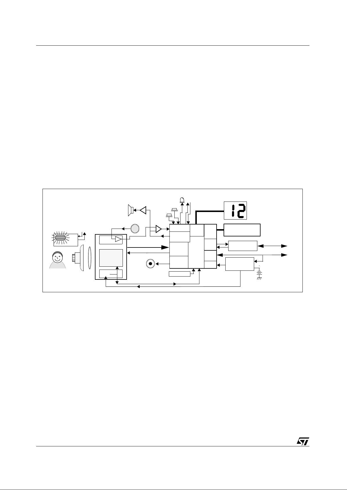
Figure 1: Typical camera system block diagram
CMOS Sensor
Sensor data
STV0681
USB interface
16MBit or 64MBit
SDRAM
Lens +
RS232
I/F
USB
I/F
memory
I/F
RS232 interface
GPIO
Sensor
I/F
PWM
LED
4.5 - 6v Battery e.g.
12MHz XTAL
Audio DAC
LCD
Driver
2x7seg.LCD
Push
Transceiver
Piezo
“Mode”
Buzzer
“Shutter
4-5v (Nominal) supplyfrom Battery or USB
3-4 x AA, AAA, etc.
Power
Management
Circuit (Discretes)
Detect Low
Battery
to PC
to PC
Circuit (Discretes)
Sensor clock
IR Filter
VV6501 (VGA)
VV6411 (CIF)
Image Array
Audio
Pre-Amp
Speaker
Microphone
Compara t or
Buttons:
/Record”
OEM Flashgun
Enable/Trigger
Module
Audio
Enable/Trigger
Flashgun
Amplifier
VReg
3v3 supply
Subject

ADCS 7283313C 7/44
STV0681 Introduction
1.2.2 User features on camera
● Self-timer mode allows a picture to be captured after several seconds.
● Twin 7 segment LCD panel supported - showing number of pictures left, and modes.
● Picture counter helps the user to know how much memory is left.
● Un-tethered ‘Continuous’ mode allows capture of image sequences for storage in memory and
subsequent download to PC.
● Piezo buzzer indicates a number of useful events to the user, e.g. whether enough light is present for
picture capture, etc.
● LED indicator .
● “Clear all” function clears camera.
● “Low Resolution” mode increases number of images which can be captured by reducing image
resolution.
● Audio Record function (if audio record hardware detected) allows sounds to be recorded.
● Audio Playback function (if audio playback hardware fitted) allows sounds which have been recorded
to be played back.
● “Delete last” function allows user to delete audio memos, pictures or continuous clips, deletion must
be carried out “most reset first”.
● Camera can be configured by the user to play custom sounds at certain functions, using a PC
application.
● “Go to sleep” function, whereby the camera can be put into standby mode while untethered.
1.2.3 User features on PC software
PC software allows a number of features such as fast download of thumbnail images for picture
selection, and automatic detection and correction of sensor defects. The driver compatibility
includes:
● TWAIN driver to suit all TWAIN compatible imaging applications
● Video for Microsoft Windows PC driver for tethered video mode (through USB), available at all
resolutions, with fastest framerates at QCIF resolution
● AVI video file creation from image sequences captured in ‘continuous’ mode
● Quicktime Video driver and Adobe Photoshop stills plug-in for Mac
Custom OEM PC software can be de v el oped b y using the SDK (for SDK av ailabi lity, contact ST), to
upload thumbnails/still images or ‘continuous’ images, e.g. for AVI file creation.
The SDK (version 2.90 or later) allows:
● the OEM to write a custom application and upload sound memos based on the example LCDC demo
software.
● the OEM to write a custom application and download custom sounds to the camera based on the
example CustomSound software.
1.2.4 Power management features and USB compliance
● Retention of pictures, recorded sounds and downloaded custom sounds with extremely low power
operation. The camera seems to be “switched off”.
● Auto power-off after 30 seconds of non usage.
● Operates from 4.5-6V battery, although system voltage is 5V or 3.3V, dependant on sensor.
● Low battery detection.

Introduction STV0681
8/44 ADCS 7283313C
● Dependant on hardware configuration, switch-over to USB power supply is supported and the device
can operate with low batteries or without batteries when connected to USB.
● Full USB compliance requirements are listed in the USB specificati on. How e ver, in a camera designe d
using this chipset, the following must at least be included: (a) an SDRAM with sufficiently low selfrefresh current, (b) USB inrush protection circuitry to maintain sufficient supply voltage to the 5V
sensor. See
Section 7
for further details.
1.2.5 General features
● High speed picture/sounds upload to PC/Mac over USB
● ST colour processing algorithms included under license (as part of drivers/SDK)
● USB or RS232 serial interface options, and VfW / TWAIN driver support.
ADCS 7283313C 9/44
STV0681 Detailed Features
2 Detailed Features
2.1 Sensor type and image formats
The sensor type is auto-detected by STV0681, the correct sensor timing is enab led and the corr ect
image resolutions are enabled, as shown in
Table 1
.
For stills photogr aph y, ‘High’ or ‘Low’ resolution mode can be selected, to give CIF or QCIF pictures
from a CIF sensor , a nd V GA o r QVGA from a V GA sensor ( see
Table 1
). Reduced resolution allo ws
for storage of more images. Images captured in both ‘High’ and ‘Low’ resolution can be stored in
camera memory at the same time. Therefore there is no need to clear images stored in memory
prior to changing image resolution.
Where USB is connected, the host PC software (through a Video for Microsoft Windows driver)
can activate tethered video mod e, re gardle ss of the user inputs to the camer a b uttons . In this case ,
the image resolution is controlled by the PC driver.
Note: When tethered VfW video (PC) or Quicktime driver (Mac) is activated, all images or recorded
sounds or video clips are deleted from the camera SDRAM. A software solution is available
(“Camera control”, as p art of the SDK for PC , and “P lug’n Sav e” f or Mac) wh ich can monitor wheth er
a camera is connected and warns the user if activating the VfW driver causes SDRAM contents to
be deleted.
Note: 1 VfW framerate is dependent on PC performance and USB bus loading
2 The number of images which can be stored is reduced if Audio sounds have been recorded on the
camera or if custom sounds have been downloaded from the PC to the camera. The reduction of
capacity depends on the length of audio clip , b ut a rough guide is that if 1 CIF i mage uses the same
amount of SDRAM as 10sec of audi o , and one VGA image uses the sam e amount of S DRAM as 30
sec. of audio.
3 A CIF camera with ST V0681 an d 64Mbit SDRAM can store up to 320 images by using QC IF mode .
When more than 99 images are available, the LCD display remains at 99. When the number of
available images is inferior to 99, the LCD display shows the number of available images like in all
other modes.
Table 1: Image modes supported
Sensor
Image Size
Resolution
mode
Final Image Size
Max. no. of
images
stored in
16MBit
memory
(
Note 2
)
Max. no. of
images
stored in
64MBit
memory
(
Note 2
)
Approximate
VfW framerate
(
Note 1
)
CIF 352 x 288 High CIF 352 x 288 20 80 15 frames/sec.
Low QCIF 176 x 144
(Subsampled)
80 322
(see
Note 3
)
22.5 frames/sec.
VGA 640 x 480 High VGA 640 x 480 ( 6) 26 2 frames/sec.
Low QVGA 320 x 240
(Subsampled)
(26) 107
(see
Note 3
)
12 frames/sec.

Detailed Features STV0681
10/44 ADCS 7283313C
2.1.1 IR filter
For IR filter design, the best choice filter follows the GS0034 dielectric stack filter specification
available from STMicroelectronics. An alternative, although not optimal filter, would be Schott
S8612 doped glass also sold as CM500.
2.2 User interface
The user interface supported by S TV0681 comprises of user controls , b uzzer sounds or customized
sounds and visual displays.
2.2.1 Push buttons
The following are the functions which are supported by the chipset. These functi ons are achie vable
with no more than 2 push buttons.
1 Mode button (wake-up/switch between modes)
This button allows the user (1.1) to wake the camera up from standby mode when the camera
is to be used for taking pictures, or (1.2) to switch between modes of operation shown in
Chapter 3
.
2 Shutter button (shutter/confirm action)
This button allows the user to take a picture or confirm an action, as shown in
Chapter 3
The modes of operation are described in
Chapter 3
.
It may also be desirable to include an on-off slider switch. The advantages and disadvantages as
well as its exact function are discussed in the reference design available from STMicroelectronics.
When a flashgun module is included in the camera, it is necessary to include a flash on/flash off
push button or slider switch depending on the exact flashgun module design. Possible
implementations are discussed in a separate application note AN1312 available from
STMicroelectronics.
2.2.2 LED indicator
The LED indicator displays the camera status when not in Standby/PC suspend mode.
2.2.3 Picture counter using 2 x 7 segment display
STV0681 stores a picture counter value indicating how many images can still be captured.
STV0681 supports a 2x7 segment LCD panel. In ‘Snapshot’ mode and continuous capture mode,
this LCD panel displa ys the number of pictures still a v ailab le. This is useful to identify w hen the user
is approaching the maximum number of images which can be stored (see
Table 1
). The user can
clear the images stored in memory and continue taking pictures. In other modes, this LCD panel
displays a 2-character code that helps the user to navigate around the modes.
Note: A CIF camera with STV068 1 and 64 Mbit SDRAM can stor e up to 320 im ages b y usin g QCIF mode .
When more than 99 images are still available, the LCD display remains at 99. When the number of
available images is inferior to 99, the LCD display shows how many images are available like in all
other modes.
For suitable numeric LCD panel types, see
Section 4.7
.

ADCS 7283313C 11/44
STV0681 Detailed Features
2.2.4 Piezo buzzer
An on-chip pulse width modulator (PWM) generates buzzer sounds to signal certain events. The
distinctive sounds are characteristic of the type of e vents in dicated by the b uzzer , as described here
below .
1 Camera has been ‘Woken up’ from standby mode (either by the user pressing a button, by re-
connecting the power source, or by connecting a USB/RS232 connection).
2 Camera has ‘gone to sleep’ that is mov ed into standby mode. Pictures are retained in memory.
3 Picture was taken successfully once the user had pressed the capture button.
4 Picture has NOT been taken when the user pressed the capture button because of insufficient
light, or because the exposure control was not rea dy fol lowi ng a rapi d change of lighting in the
scene.
5 Picture has NOT been taken when the user pressed the capture button because the picture
counter had reached the maximum number of images. The user has the chance to reset the
counter if desired.
6 End of continuous capture in un-tethered ‘Continuous’ mode due to full memory.
7 Self-timer activated, count down has started.
2.2.5 Custom sounds
A camera which includes STV0681 and audio pla ybac k har dw are can ha v e a set of custom sounds
downloaded from a PC application. A different sound can be associated with each of the following
functions:
Table 2: List of custom sound functions
Power On
Power Off
Good picture
Bad picture
(Normally due to insufficient light)
Memory full
Self timer #1
Self timer #2
Low resolution
High resolution
Picture delete
Sound delete
Continuous clip delete
Clear memory
Confirm action
Low power
Flashgun ON
Flashgun OFF
Flashgun Trigger

Detailed Features STV0681
12/44 ADCS 7283313C
Note: 1 When a sound is associated to a given function, and it is stored in SDRAM, the piezo buzzer does
not give any beeps for that function. Not all functions need to have custom sounds associated with
them, this is the choice of the user or OEM.
2 A demonstration PC ap pl ication “CustomSounds” is available from ST, howe ver this is not intend ed
for end-users. Source code is available which allows the OEM to build their own PC application
using the SDK.
2.3 Battery level detect and USB auto-switch
An on-chip battery level detector on STV0681 detects when the battery voltage falls below a
threshold. The chosen threshold level is determined by a resistor value, as shown in
Chapter 7
.
Where no USB has been detected, the LCD displa y flashes , indicating that the battery is low. When
a USB connection has been detected, the LCD display does not flash.
Note: It may be a requirement of certain USB compliance tests that such additional hardware is included
in the camera design, in or der to e nab le the cam era to s wi tch to supply fr om USB a nd hence re port
back to the PC while connected to the USB bus without a battery.
2.4 Audio record and playback
2.4.1 Record
A camera including the STV0681 with a microphone, a compa r ator a nd o t her periph ery (also using
the sensor pre-amplifier) can record sounds stored like images. STV0681 auto-detects the
presence of audio record hardware and includes audio record and “delete last” functions into the
user interface. The audio sample rate is 11.025 kHz, the signal is digitized using a successive
approximation A-D conv erter with 8 bits resolu tion. The SDRAM stor es 1 second of audio r ecording
per 11 kByte of memory.
2.4.2 Playback
A camera including the STV0681 with an amplifier, a speaker/headphone socket and other
periphery can playback sounds either recorded on the camera or downloaded from the PC.
The quality of audio playback is largely dependant on the type of speaker used, and on the correct
mounting of the speaker in the camera plastics.
Frequency 50kHz
Frequency 60kHz
Table 2: List of custom sound functions

ADCS 7283313C 13/44
STV0681 Detailed Features
2.5 PC interface options and software support
USB interface (full speed 12Mbit per second maximum) and RS232 interface (115.2kbaud) are
supported by the chipset, with driver software available from STMicroelectronics for both. The
interface type is auto-detected by the chipset. PC software can be one of the following:
1 Simple image upload demonstration software supplied by ST, allowing uploading of stills or
‘continuous’ images. This software should not be supplied as an end-user product.
2 TWAIN driver to suit all TWAIN compatible imaging applications,
3 Video for Microsoft Windows driver for tethered video mode (USB only),
4 Custom end-user software developed by OEM using SDK (for SDK availability, contact ST).
The SDK is supplied by ST as a 32-bit DLL format, running on Microsoft Windows 98, and
accessed through a documented software interface. This provides the basis for developing a
custom software application for uploading stills and/or video.
2.5.1 USB
Complete images (displayed as either thumbnails or in full resolution), or the entire SDRAM
contents (e.g. for uploading continuously captured image sequences, recorded using ‘Continuous
Capture’ mode) can be downloaded through USB, and USB connection also allows for tethered
video mode to be activated by the USB driver.
Thumbnail image download i s e xtre mely f ast f or the entire memory contents in the camera. Once a
picture is selected for download, full image download takes approximately 0.15 second per image
for a CIF image (0.6 second for a VGA image), plus post processing time per image.
For USB interface details, see
Section 4.3
.
Note: Actual USB download and post processing time also depends on PC performance and USB bus
loading
2.5.2 RS232
Thumbnails of images , comple te stored images , or the en tire SDRAM contents ca n be do wnload ed
through RS232, but tethered video is not supported.
Once a picture is selected for download, full image download takes approximately 10 seconds per
image for a CIF im age ( ar ound 30 secon ds for a VGA imag e), pl us post pr ocessin g time per i mage
(of the order of 1 second approximately).
For RS232 interface details, see
Section 4.4
.
Note: Actual post processing time after RS232 download also depends on PC performance
Detailed Features STV0681
14/44 ADCS 7283313C
2.6 Anti-flicker exposure and gain control
2.6.1 General
The chipset operates automatic exposure and gain control for either 50Hz or 60Hz mains-driven
indoor lighting, using the same 12MHz crystal. This improves picture quality by selecting a set of
exposure values which minimize ‘flicker’ effects. Detection of the mains frequency is dependant on
the status of the GPIO3 pin, which can be achieved by population of a PCB link at a late stage in
production, once the country of destination is known, without the need to change the crystal
frequency.
The auto exposure and gain algorithm is always enabled during Snapshot’/self-timer/continuous
mode. When the shutter butt on is pressed in ‘Snapshot’ mode, the chipset captures an image if the
exposure and gain values are suitable for the current scene. If the light has suddenly changed, the
camera may emit an audible tone to indicate that more time is required to reach the correct
exposure target. In ‘Snapshot’ mode the chipset only captures the image data if sufficient light is
present in the image. In continuous capture mode, the chipset captures images regardless of
whether enough light is present.
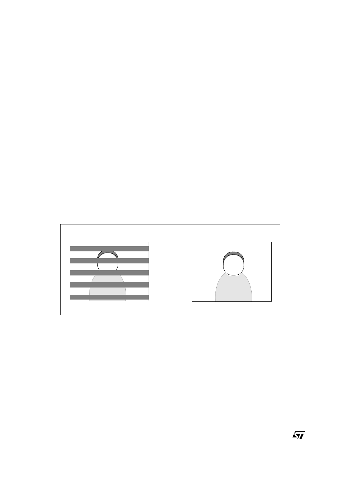
The exposure control algorithm in STV0681 chooses exposure values which minimize “flicker”
effects from occurring under fluorescent lighting. STV0681 can only prevent flicker in lighting
powered by 50Hz or 60Hz electricity supply, but automatic detection of the flicker frequency is not
possible. Hence choosing the corr ect anti-flick er setting is important, in order to prev ent dark stripes
from appearing across the image, and this selection must be done in hardware.
2.6.2 Flashgun exposure
When the STV0681 and a flashgun module are included in the camera, and the flashgun enable
signal is high, the exposure mode operates in a different manner. The CMOS sensor progressive
scan readout requires that the sensor is set to maximum exposure so that all lines are exposed.
The flashgun operates during a few 100 µs in order to correctly expose all sensor lines, (contact ST
for more precis e details), theref ore the f lashgun module design should h av e reached maximum light
output within this period after the falling edge of the flash trigger output from STV0681.
Possib le flashgun impleme ntations, regard ing hardw are interf ace, charge sensi ng, and flash energ y
required are discussed in a separate application note AN1312 available from STMicroelectronics.
Figure 2: Illustration of flicker problem
Flicker setting not correct Flicker setting correct
 Loading...