

SGS Thomson Microelectronics STV0680B Datasheet

®
STV0680B+ VV6410/6411/6500
DUAL-MODE DIGITAL CAMERA CHIPSET
DESCRIPTION
STMicroelectronics Imaging Division has enhanced
the feature set of the STV0680B low cost dualmode camera chipset to allow a new line of low cost
cameras or toy products to be brought to the
market.
STANDARD FEATURES
ST have maintained the standard features already
available in the successful STV0680B-001 chipset ,
including:
● STV0680B-003 fully backward compatible
with STV0680B-001
● Support for VV6410/6411 (CIF) and VV6500
(VGA) CMOS imaging sensors.
● Support for SDRAM sizes 16MBit (up to 20
CIF images) or 64Mbit (up to 80 CIF or 26
VGA images).
● Low resolution “economy” mode allows for
more images to be stored.
● High frame rate web cam (tethered video)
over USB.
● Automatic anti-flicker exposure control.
● Image up load over RS232 or USB.
● Driver support for Win98/Win2k/WinME and
MacOS 8.6/9.0/9.1.
● Continuous capture while untethered (except
when Flashgun enabled) an d downloadi ng to
AVI file format
● Power-saving “stand-by” mode which
maintains memory contents, as well as
generally low power consumption.
● Simple user interface including 2 buttons,
status LCD display, and buzzer.
● Evaluation Kit (EVK) available.
● Software Development Kit ( SDK) allows OEM
PC Software applications to be written.
NEW FEATURES AVAILABLE IN STV0680B-003
● Audio record/playback and “Delete Last”
function
● Custom sounds playback (e.g. “Talking” or
“Musical” camera)
● Flashgun support
● Quick Power Down (by holding Mode
Button).
Audio Record And Playback
The enhanced features included in STV0680B-00 3
allow audio memos to be recorded, stored in
SDRAM, and uploaded to the PC over USB or
RS232, to be played back using an OEM software
application developed using the SDK
With the addition of playback hardware, recorded
audio sounds can also be played back on the
camera, and it is possible to download a set of
custom sounds from the PC to allow (e.g.) shutter
“Click-Whirr”, or for a “Talking Camera”. This has
limitless possibilities for OEM language
customising or licensing.
Flashgun Support and “Delete Last” Function
STV0680B-003 includes flashgun support for an
OEM flashgun module. A n additio nal u ser in terface
function is available in STV0680B-003 w hich allows
the user to delete the last image, continuous clip or
audio memo which was captured or recorded.
Evaluation Kit and Reference Design
Evaluation kits are available for both standard
features and enhanced STV0680B-003 features.
Precise design guidelines ar e avai l able fr om ST as
a separate STV0680B Reference design manual
(see
Chapter 12
).
Note: Simultaneous audio record and
continuous video capture is not possible.
September 2001 Version 3.4 1/63

STV0680B+ VV6410/6411/6500
Table of contents
Chapter 1 Introduction . . . . . . . . . . . . . . . . . . . . . . . . . . . . . . . . . . . . . . . . . . . . . . . . . . . . . .6
1.1 Digital camera chipset ..........................................................................................................6
1.2 Co-processor choices ..........................................................................................................7
1.3 Sensor choices .....................................................................................................................7
1.4 Key system features .............................................................................................................7
Chapter 2 Detailed features . . . . . . . . . . . . . . . . . . . . . . . . . . . . . . . . . . . . . . . . . . . . . . . . .10
2.1 Sensor type and image formats .........................................................................................10
2.2 User interface .....................................................................................................................11
2.3 Battery level detect and USB auto-switch ..........................................................................13
2.4 Audio record and playback .................................................................................................13
2.5 PC interface options and software support ........................................................................14
2.6 Anti-flicker exposure and gain control ................................................................................15
Chapter 3 Camera modes of operation . . . . . . . . . . . . . . . . . . . . . . . . . . . . . . . . . . . . . . . .16
3.1 Modes available (STV0680B-001) .....................................................................................16
3.2 Modes available (STV0680B-003) .....................................................................................17
3.3 Description of modes .........................................................................................................17
Chapter 4 STV0680B hardware interfaces . . . . . . . . . . . . . . . . . . . . . . . . . . . . . . . . . . . . . .20
4.1 STV0680B pinout ...............................................................................................................20
4.2 Sensor interface .................................................................................................................20
4.3 Memory interface ...............................................................................................................20
4.4 USB interface ................................................................ ........... ........... ........... ........... .........22
4.5 UART module for RS232 interface .....................................................................................23
4.6 Power management and battery type ................................................................................23
4.7 Quartz crystal .....................................................................................................................24
4.8 Numeric LCD interface .......................................................................................................24
4.9 Switches and LED’s ...........................................................................................................24
4.10 Flashgun hardware interface (STV0680B-003 only) ..........................................................25
4.11 IR filter ...................................................................................... ..........................................25
Chapter 5 Software support . . . . . . . . . . . . . . . . . . . . . . . . . . . . . . . . . . . . . . . . . . . . . . . . .26
2/63 Version 3.4

STV0680B+ VV6410/6411/6500
5.1 General features ................................................................................................................26
5.2 Software installation ...........................................................................................................26
Chapter 6 Detailed chipset specifications . . . . . . . . . . . . . . . . . . . . . . . . . . . . . . . . . . . . . .28
6.1 Typical camera specifications ............................................................................................28
6.2 STV0680B companion processor ......................................................................................29
6.3 VV6444 sensor ...................................................................................................................30
6.4 VV6410/6411 and VV6500 sensors ...................................................................................32
6.5 Typical current consumption of complete camera ..............................................................33
Chapter 7 STV0680 Camera System Defect Specification . . . . . . . . . . . . . . . . . . . . . . . . .35
7.1 General ..............................................................................................................................35
7.2 Defect specification ............................................................................................................35
7.3 Definition of the "Camera System" .....................................................................................35
7.4 Definition of the "Test Conditions" ......................................................................................37
7.5 Definition of a "Major Visible Defect" ..................................................................................37
7.6 Definition of the "Final Colour Image" ................................................................................39
7.7 Definition of a “Minor Visible Defect” ..................................................................................39
Chapter 8 STV0680B pinout information and package dimensions . . . . . . . . . . . . . . . . .40
8.1 STV0680B pinout ...............................................................................................................40
8.2 STV0680B pin description ..................................................................................................46
8.3 STV0680B package dimensions ........................................................................................47
Chapter 9 VV6410/6411 pinout information and package dimensions . . . . . . . . . . . . . . .48
9.1 VV6410/6411 pinout ............................................................................ ........... ........... .........48
9.2 VV6410/6411 pin description ............................................................................................49
9.3 VV6410/6411 package dimensions ........................................................................... .........51
Chapter 10 VV6500 pinout information and package dimensions . . . . . . . . . . . . . . . . . . .53
10.1 VV6500 pinout ....................................................................................................................53
10.2 VV6500 pin description ......................................................................................................54
10.3 VV6500 package dimensions .............................................................................................56
Chapter 11 Schematics and example parts list . . . . . . . . . . . . . . . . . . . . . . . . . . . . . . . . . . .58
11.1 Schematics .........................................................................................................................58
Version 3.4 3/63

STV0680B+ VV6410/6411/6500
11.2 Example parts list ...............................................................................................................58
Chapter 12 Evaluation Kit and Reference design manual . . . . . . . . . . . . . . . . . . . . . . . . . .61
12.1 Ordering details ..................................................................................................................61
12.2 Technical support ...............................................................................................................62
4/63 Version 3.4

STV0680B + VV6444/6410/6500
Revision update
Main changes applied since last release, version 3.3:
● Updated camera defect specification
Version 3.4 5/63
Introduction STV0680B + VV6444/6410/6500
1 Introduction
1.1 Digital camera chipset
This document describes the features and functionality of a CMOS chipset, comprising an
STMicroelectronics (ST) CIF or VGA resolution sensor and an STV0680B companion processor
(DCA1), as well as outlining what peripheral components are required/supported in order to
complete a camera using the chipset. Such a camer a is particul arly suited to dual- mode digital stills
or toy applications.
In stills mode, the camera stores raw image data in memory. The camera carries out no colour
processing, ensuring its simplicity and low cost. Subsequent download of raw data to a PC or
Macintosh for processing is done through an RS232 or USB interface, through demo software, a
TWAIN driver, or OEM custom application. The license to use the colour algorithm (embedded in
the PC or Mac driver software) is included in the price of the chipset.
A video option is provided, when tethered through USB, which can allow for Video for Windows
applications, and ‘video clips’ can be recorded while untethered by continuously capturing images
while in ‘Continuous’ mode, then downloaded to the PC for playback, using software to create an
AVI file.
Using STV0680B-003, the firmware also includes the capability to trigger a flashgun module
through a two wire interface (enable input and trigger output), and the capability to record audio
sounds into the SDRAM, for subsequent upload to the PC, or to replay audio sounds which have
either been recorded on the camera or dowloaded from the PC (stored on the PC as.WAV files).
Precise design guidelines are available from ST as a reference design (see
Section 4
). A software
development kit (SDK) for PC is avai lable from ST, to interface to th e camera a nd provid e the basis
for developing a custom software application for stills and/or video, which includes colour
processing software as object code.
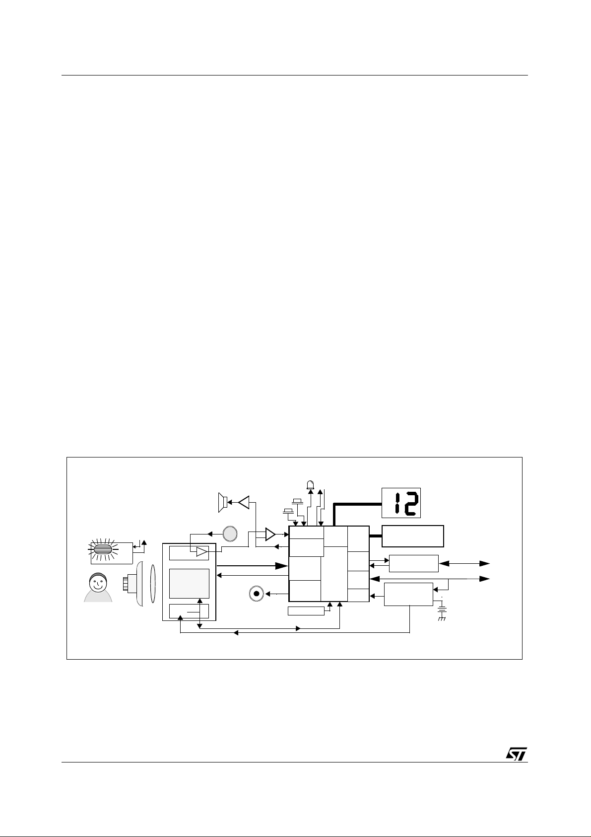
LED
GPIO
Sensor
I/F
PWM
Flashgun
Enable/Trigger
LCD
memory
Driver
STV0680B
I/F
RS232
I/F
USB
I/F
Detect Low
Battery
2 x 7 seg. LCD
16MBit or 64MBit
SDRAM
Transceiver
Circuit (Discretes)
Power
Management
Circuit (Discretes)
RS232 interface
to PC
USB interface
to PC
4.5 - 6v Battery e.g.
3-4 x AA, AAA, etc.
OEM Flashgun
Module
Subject
CMOS Sensor
VV6410/6411(CIF)
VV6500 (VGA)
Enable/Trigger
Lens +
IR Filter
Audio
Pre-Amp
Image Array
VReg
Audio
Speaker
Microphone
Amplifier
Sensor data
Sensor clock
Piezo
Buzzer
Push
Buttons:
“Mode”
“Shutter
/Record”
Comparator
Audio DAC
12MHz XTAL
3v3 supply
4-5v (Nominal) supply from Battery or USB
Figure 1 : Typical camera system block diagram
6/63 Version 3.4
STV0680B + VV6444/6410/6500 Introduction
1.2 Co-processor choices
Two revisions of the STV0680B are produced by ST. Although there are certain functional
differences between these revisions, both have an identical pinouts and STV0680B-003 retains all
the functionality of STV0680B-001, hence is backwards compatible.
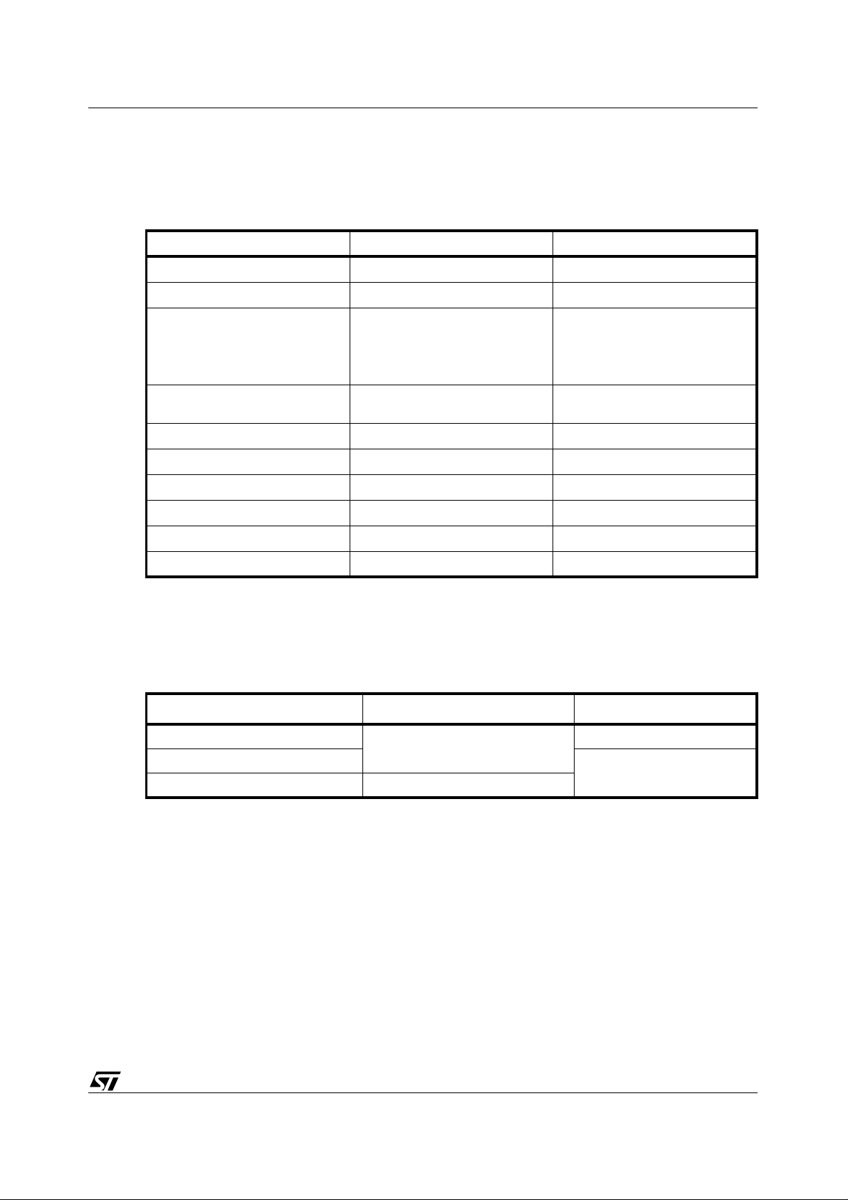
Order number STV0680B-001 STV680B-003
Silicon revision
Firmware revision
Sensor supported
SDRAM supported
USB
RS232
Video for Windows support
Flash-gun support
Audio record + playback
Custom sounds
Table 1 : Differences between STV0680B-001 and STV0680B-003
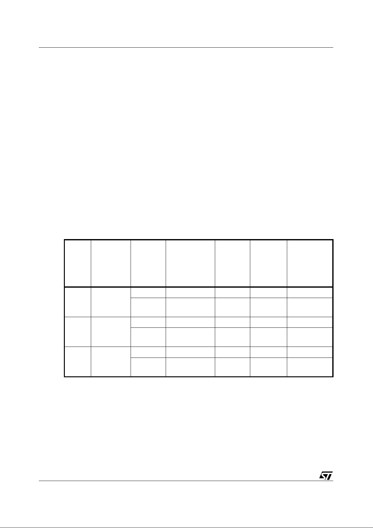
1.3 Sensor choices
The following sensors are supported:
STV0680B STV0680B
v1.00 v3.00
VV6444
VV6410
VV6500
16Mbit
or 64Mbit
Yes Yes
Yes Yes
Yes Yes
No Yes
No Yes
No Yes
VV6444
VV6410
VV6411
VV6500
16Mbit
or 64Mbit
Sensor Resolution Sensor supply voltage
VV6444
VV6410/6411
VV6500 VGA (640 x 480)
Table 2 : Sensor choices with STV0680B
1.4 Key system features
The key features of a typical camera based on the STV0680B chipset are as follows:
1.4.1 Image features (STV0680B-001)
● Support for 5V or 3.3V CIF resolution sensor (VV6444 or VV6410/6411) - 352 x 288 pixels
● Support for 3.3V VGA resolution sensor (VV6500) - 640 x 480 pixels
● 80 picture storage capacity possible for CIF, with 64MB memory
● 26 picture storage capacity for VGA, with 64MBit memory
CIF (352 x 288)
5v
3.3v
Version 3.4 7/63

Introduction STV0680B + VV6444/6410/6500
● A greater number of images can be stored when ‘Low’ resolution mode is enabled (e.g. 80
QCIF images with 16Mbit memory, 107 QVGA images with 64Mbit memory). See
● Automatic anti-flicker exposure and gain control
Table 3
.
1.4.2 Image features (STV0680B-003)
● All image features for STV0680B-001 are supported.
● Support for flashgun.
1.4.3 User features on camera (STV0680B-001)
● Self-timer mode allows a picture to be captured after several seconds.
● Twin 7 segment LCD panel supported - showing number of pictures left, and modes.
● Picture counter helps the user to know how much memory is left.
● Un-tethered ‘Continuous’ mo de all ow s captur e of i mage sequen ces for storage i n mem ory and
subsequent download to PC.
● Piezo buzzer indicates a number of useful events to the user, e.g. whether enough light is
present for picture capture, etc.
● Indicator LED.
● “Clear all” function clears camera.
● “Low Resolution” mode incre ases number of images wh ich can be captur ed by reducing image
resolution.
1.4.4 User features on camera (STV0680B-003)
● All user features of STV0680B-001 are supported.
● Audio Record function (if audio record hardware detected) allows sounds to be recorded.
● Audio Playback function (if audio playback hardware fitted) allows sounds which have been
recorded to be played back.
● “Delete last” function allows user to delete audio memos, pictures or continuous clips, deletion
must be carried out “most reset first”.
● Camera can be configured by the user to play custom sounds at certain functions, using a PC
application.
● “Go to sleep” function, whereby the camera can be put into standby mode while untethered.
1.4.5 User features on PC software (STV0680B-001)
PC software allows a number of features, including fast download of thumbnail images for picture
selection, and automatic detection and correction of sensor defects. The driver compatibility
includes:
● TWAIN driver to suit all TWAIN compatible imaging applications
● Video for Windows PC driver for tethered video mode (through USB), available at all
resolutions, with fastest framerates at QCIF resolution
● AVI video file creation from image sequences captured in ‘continuous’ mode
● Quicktime Video driver and Adobe Photoshop stills plug-in for Mac
Custom OEM PC software can be developed by using t he SDK (for SDK a vailabilit y, contact ST), to
upload thumbnails/still images or ‘continuous’ images, e.g. for AVI file creation.
8/63 Version 3.4

STV0680B + VV6444/6410/6500 Introduction
1.4.6 User features on PC software (STV0680B-003)
All PC software written for a STV0680B-001 camera will function with a STV0680B-003 camera
which is only used to take still images/video.
The SDK (version 2.90 or later) allows for:
● the OEM to write a custom application for uploading sound memos, based on the example
LCDC demo software.
● the OEM to write a custom application for downloading custom sounds to the camera, based
on the example CustomSound software.
1.4.7 Power management features and USB compliance
● Retention of pictures, recorded sounds, and downloaded custom sounds with extremely low
power operation, which appears to the user as if the camera is “switched off”.
● Auto power-off after 30sec with no user activity
● Operates from 4.5-6V battery, although system voltage is 5V or 3.3V, dependant on sensor.
● Low battery detection
● Dependant on hardware configura t io n, swit ch-over to USB power supply is supported, to allow
the device to operate with low batteries or without batteries, when connected to USB.
● Full USB compliance requirements are listed in the USB specification, however, in a camera
designed using this chipset, the following must at least be included: (a) an SDRAM with
sufficiently low self-refresh current, (b) USB inrush protection circuitry, and (c) (in the case of
VV6444 only) a switched 5V sensor supply is used, to maintain sufficient supply voltage to the
5V sensor. See
Section 4
for further details.
1.4.8 General features
● High speed picture/sounds upload to PC/Mac over USB
● ST Colour processing algorithms included under license (as part of drivers/SDK)
● USB or RS232 serial interface options, and VfW / TWAIN driver support.
Version 3.4 9/63
Detailed features STV0680B + VV6444/6410/6500
2 Detailed features
2.1 Sensor type and image formats
The sensor type is auto-detected by STV0680B, which ensures that the correct sensor timing is
enabled, and the correct image resolutions are enabled, as shown in
For stills photography, ‘High’ or ‘Low’ resolution mode can be sele cted, to give CIF or QCIF pictures
from a CIF sensor, and VGA or QVGA from a VGA sensor (see
for storage of more images. Images captured in both ‘High’ and ‘Low’ resolution can be stored in
camera memory at the same time. Therefore there is no need for images stored in memory to be
cleared before changing image resolution.
Where USB is connected, the host PC software (through a Video for Windows driver) can activate
tethered video mode, regardless of the user inputs to the camera buttons. In this case, the image
resolution is controlled by the PC driver.
Note: When tethered VfW video (PC) or Quicktime driver (Mac) is activated, all images or recorded
sounds or video clips will be deleted from the camera SDRAM. A software solution is available
(“Camera control”, as part of the SDK for PC, and “Plug’n Save” for Mac) which can monitor
whether a camera is connected and will warn the user if activating the VfW driver will cause SDRAM
contents to be deleted.
Table 3
Table 3
.
). Reduced resolution allows
Sensor
VV6444 CIF 352 x 288
VV6410/
6411
VV6500 VGA 640 x 480
Sensor
Image Size
CIF 352 x 288
Max. no. of
images
Resolution
mode
High CIF 352 x 288 20 80 15 frames/sec.
Low
High CIF 352 x 288 20 80 15 frames/sec.
Low
High VGA 640 x 480 (6) 26 2 frames/sec.
Low
Table 3 : Image modes supported (STV0680B-001)
Final Image Size
QCIF 176 x 144
(Subsampled)
QCIF 176 x 144
(Subsampled)
QVGA 320 x 240
(Subsampled)
stored in
16MBit
memory
(
Note 2
80
80
(26)
)
Max. no. of
images
stored in
64MBit
memory
(
Note 2
)
322
Note 3
(see
322
(see
Note 3
107
Note 3
(see
Approximate
VfW framerate
25 frames/sec.
)
22.5 frames/sec.
)
12 frames/sec.
)
Note: 1 VfW framerate is dependent on PC performance and USB bus loading
2 On a camera using STV0680B-003, the number of images w hich can be stor ed i s reduced if Aud io
sounds have been recorded on the camera or if custom sounds have been downloaded from the
PC to the camera. The reduction of capacity depends on the length of audio clip, but a rough guide
is that if 1 CIF image uses the same amount of SDRAM as 10sec of audio, and one VGA image
uses the same amount of SDRAM as 30 sec. of audio.
(
Note 1
)
10/63 Version 3.4

STV0680B + VV6444/6410/6500 Detailed features
3 A CIF camera with STV0680B-001 and 6 4Mbi t SD RAM can store up to 320 i mag es by using QC IF
mode. Where >99 images are still available, the LCD display will remain at 99. Where (no. of
images available) <99, the LCD display will show the number of images available, as is the case
with all other modes.
2.1.1 VV6444
VV6444 is a CIF resolution, 5V CMOS imaging sensor and has been superseded by VV6410/6411.
2.1.2 VV6410
VV6410 is a CIF resolution, 3.3V CMOS imaging sensor . A brief specification is shown in
A dual design to support VV6444 and VV6410/6411 is not possible, since VV6410/6411 is a 3v3
sensor. A single footprint for VV6410/6411 and VV6500 is not possible since the package types
differ, however, the same support circuit is used.
For IR filter design, the best choice filter follows the GS0034 dielectric stack filter specification,
which is available from ST. An alternative, al though not optimal filter, would be Schott S8612 doped
glass, also sold as CM500.
2.1.3 VV6411
VV641 1 is a CIF re solution, 3.3V CMOS imag ing sensor. A brief specification is shown in
The functionality, pixel size, resolution and support circuit are identical to VV6410, however, the
colour filter material is slightly different, and the package type and pinout may differ to VV6410.
Contact ST for further details.
A single footprint to support VV641 1 a nd VV6500 is not possible because of the package dif ference.
A single footprint to support VV641 0 and VV6411 may be possible, dependant on the final package
for VV641 1.
2.1.4 VV6500
VV6500 is a VGA resolution, 3.3V CMOS imaging sensor. A brief specification is shown in
Chapter 6
A dual design to support VV6444 and VV6500 is not possible, since VV6500 is a 3v3 sensor. A
single footprint for VV6410/6411 and VV6500 is not possible since the package types differ,
however, the same support circuit is used. See
Chapter 6
Chapter 6
Chapter 6
.
.
.
For IR filter design, the best choice filter follows the GS0034 dielectric stack filter specification,
which is available from ST. An alternative, al though not optimal filter, would be Schott S8612 doped
glass, also sold as CM500.
2.1.5 SDRAM
This is covered in more details in
2.2 User interface
The user interface supported by STV0680B comprises of user controls, buzzer sounds or
customised audio sounds and visual displays.
2.2.1 Push buttons
The following are the functions which are suppor ted by the chipse t. These functio ns are achievabl e
with no more than 2 push buttons.
Chapter 4
.
Version 3.4 11/63

Detailed features STV0680B + VV6444/6410/6500
1 Mode button (Wake-up/Switch between modes): This button allows the user (1.1) to wake the
camera up from standby mode when the camera is to be used for taking pictures, or (1.2) to
switch between modes of operation shown in
2 Shutter button (Shutter/confir m acti on)
an action, as shown in
Chapter 3
: This button allows the user to take a picture or co nfirm
Chapter 3
.
The modes of operation are described in
It may also be desirable to include an on-off slider switch. This has advantages and disadvanta ges,
and its exact function is discussed further in the reference design available from ST.
Where a flashgun module is included in the camera, it will be necessary to include a flash on/flash
off push button or slider switch, dependant on the exact flashgun module design. possible
implementations are discussed in a separate application note AN1312 regarding flashgun
implementation, available from ST.
Chapter 3
.
2.2.2 LED indicator
An LED display camera status, i.e. to show that the camera is not in Standby/PC suspend mode.
2.2.3 Picture counter using 2 x 7 segment display
STV0680B stores a picture counter value, which shows how many images can still be captured.
STV0680B supports a 2x7 segment LCD panel. In ‘Snap shot’ mode and contin uous capture m ode,
this LCD panel displays the number of pictures still available, which is useful to identify when the
user is approaching the maximum number of images which can be stored (see
possible to clear the images stored in memory, in order to continue taking pictures. In other modes,
this LCD panel shows displays a 2-character code, which helps the user to navigate around the
modes.
Note: A CIF camera with STV0680B and 64Mbit SDRAM can store up to 320 images by using QCIF
mode. Where >99 images are still available, the LCD display will remain at 99. Where (no. of
images available) <99, the LCD display will show the number of images available, as is the case
with all other modes.
Table 3
). It is
For suitable numeric LCD panel types, see
Section 4.8
2.2.4 Piezo buzzer
An on-chip Pulse Width Modulator (PWM) on STV0680B is used to generate buzzer sounds to
signal certain events. The following are typical of the type of events which are indicated by the
buzzer, and each has its own distinctive sound:
1 Camera has been ‘Woken up’ from standby mode (either by the user pressing a button, by re-
connecting the power source, or by connecting a USB/RS232 connection).
2 Camera has been ‘gone to sleep’ i.e. moved into standby mode. Pictures are retained in
memory.
3 Picture has been successfully taken after the user presses the capture button.
4 Picture has NOT been taken after the user presses the capture button. This indicates to the
user that there is insufficient light, or that the exposure control was not ready due to a rapid
change of lighting in the scene.
5 Picture has NOT been taken after the user presses the capture button, due to picture counter
having reached the maximum num ber of i ma ges. The u ser ha s the cha nce to zer o th e counte r
if desired.
6 End of continuous capture in un-tethered ‘Continuous’ mode, due to memory full.
7 Self-timer activated and counting down.
12/63 Version 3.4
.

STV0680B + VV6444/6410/6500 Detailed features
2.2.5 Custom sounds
A camera which includes STV0680B-003 and Audio playback hardware can have a set of custom
sounds downloaded from a PC application. A different sound can be associated with each of the
following functions:
Power On Sound delete
Power Off Continuous clip delete
Good picture Clear memo ry
Bad picture
(Normally due to insufficient light)
Memory full Low power
Self timer #1 Flashgun ON
Self timer #2 Flashgun OFF
Low resolution Flashgun Trigger
High resolution Frequency 50kHz
Picture delete Frequency 60kHz
Table 4 : List of custom sound functions
Confirm action
Note: 1 Where a given function has a sound associated with it stored in SDRAM, the piezo buzzer does not
give any beeps for that function. Not all functions need to have custom sounds associated with
them, this is the choice of the user or OEM.
2 A demonstration PC application “CustomSoun ds” is available from ST, however this is not intended
for end-users. Source code is available which allows the EOM to build their own PC application
using the SDK.
2.3 Battery level detect and USB auto-switch
An on-chip battery level detector on STV0680B detects when the battery voltage falls below a
threshold. This threshold is determined by the designer, dependant on the perception of what
remains as ‘acceptable’ image quality as the battery voltage falls. The chosen threshold level is
determined by a resistor value, as sho wn in
display flashes, which indicates tha t the battery is low . Whe re a USB connection ha s been detected,
the camera sources power from USB, if certain additional hardware is fitted.
Chapter 6
Where no USB has been detected, the LCD
Note: It may be a requirement of certain USB compliance tests that such additional hardware is included
in the camera design, in order to enable th e camera to switch to supply fr om USB and hence r eport
back to the PC while connected to the USB bus without a battery.
2.4 Audio record and playback
2.4.1 Record
A camera which includes STV0680B-003 and a mi croph one, comparator and other peripher y (also
utilizing the sensor pre-amplifier) can be used to record sounds which are stored in the same way
as images. STV0680B-003 will auto-detect the presence of Audio record hardware and include
Version 3.4 13/63

Detailed features STV0680B + VV6444/6410/6500
audio record and “delete l ast” functions int o the user i nterface. The a udio sample rate is 11.025kHz,
and the signal is digitised using a successive approximation A-D converter with 8 bits resolution.
The SDRAM stores 1 second of Audio recording per 11k Bytes of memory.
2.4.2 Playback
A camera which includes STV0680B-003 and an amplifier, speaker/headphone socket, and other
periphery, can be used to playback sounds which were either recorded on the camera or
downloaded from the PC.
The quality of Audio playback is largely depe ndant on the type of speaker used, and on the correct
mounting of the speaker in the camera plastics.
2.5 PC interface options and software support
Either USB Interface (full speed 12Mbit/sec. max.) or RS232 interface (115.2Kbaud) is supported
by the chipset, with driver software available from ST for both. The interface type is auto-detected
by the chipset. PC software can be one of the following:
1 Simple image upload demonstration software supplied by ST, allowing uploading of stills or
‘continuous’ images. This software should not be supplied as an end-user product.
2 TWAIN driver to suit all TWAIN compatible imaging applications
3 Video for Windows driver for tethered video mode (USB only)
4 Custom end-user software developed by OEM using SDK (for SDK availability, contact ST).
The SDK is supplied by ST as a 32-bit DLL format, running on Windows 98, and accessed
through a documented software interface. This provides the basis for developing a custom
software application for uploading stills and/or video.
2.5.1 USB
Complete images (displayed as either thumbnails or in full resolution), or the entire SDRAM
contents (e.g. for uploading continuously captured image sequences, recorded using ‘Continuous
Capture’ mode) can be downloaded through USB, and USB connection also allows for tethered
video mode to be activated by the USB driver.
Thumbnail image download is extremely fast for the enti re memory cont ents in the camer a. Once a
picture is selected fo r down load, full image download takes approximately 0.15 seconds per ima ge
for a CIF image (0.6 seconds for a VGA image), plus post processing time per image.
For USB interface details, see
Section 4.4
.
Note: Actual USB download and post processing time also depends on PC performance and USB bus
loading
2.5.2 RS232
Thumbnails of images, complete stored images, or the entire SDR AM contents can be downloaded
through RS232, but tethered video is not supported.
Once a picture is selected for download, full image download takes approximately 10 seconds per
image for a CIF image ( aro und 3 0 second s for a VGA i mage), plus post processing time pe r i m age
(of the order of 1 second approximately).
For RS232 interface details, see
Note: Actual post processing time after RS232 download also depends on PC performance
Section 4.5
.
14/63 Version 3.4
STV0680B + VV6444/6410/6500 Detailed features
2.6 Anti-flicker exposure and gain control
2.6.1 General
The chipset operates automatic exposure and gain control for either 50Hz or 60Hz mains-driven
indoor lighting, using the same 12MHz crystal. This improves picture quality by selecting a set of
exposure values which minimise ‘f li cker’ effects. Detection o f the mai ns fr equen cy is dep endan t on
the status of the GPIO3 pin, which can be achieved by population of a PCB link at a late stage in
production, once the country of destination is known, without the need to change the crystal
frequency.
The auto exposure and gain algorithm is always enabled during Snapshot’/self-timer/continuous
mode. When the shutter button is pressed in ‘ Snapshot’ mode , the chipset captu res an image if the
exposure and gain value has reached a suitable val ue for the current scene. If the li ght detected has
suddenly changed, the camera may emit an audible tone to indicate that more time is required to
reach the correct exposure target. In ‘Snapshot’ mode the chipset only captures the image data if
sufficient light is present in the image. In continuous capture mode, the chipset captures images
regardless of whether enough light is present.
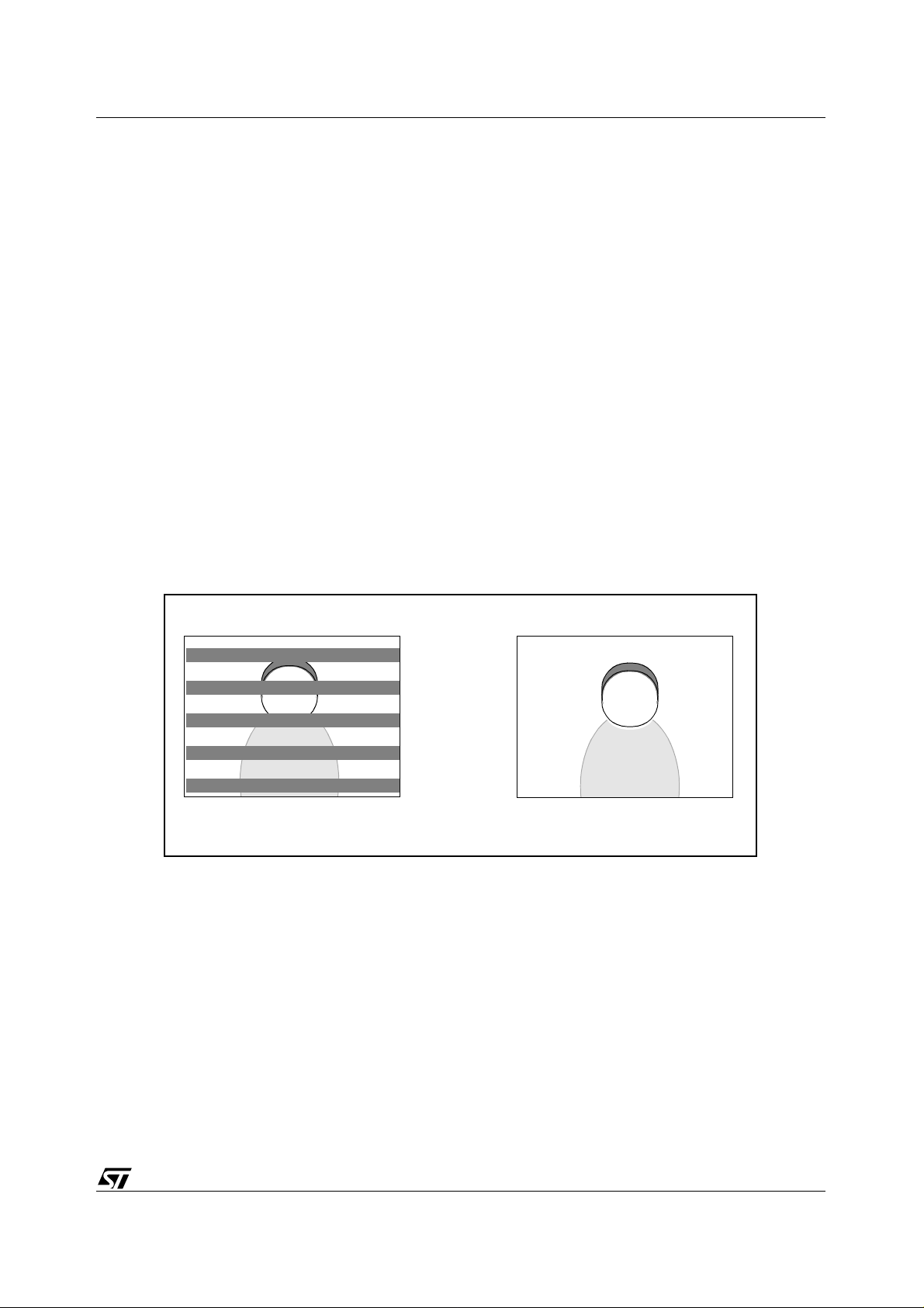
The exposure control algorithm in STV0680B chooses exposure values which minimise “flicker”
effects from occurring under fluorescent lighting. STV0680B can only prevent flicker in lighting
powered by 50Hz or 60Hz electricity supply, but automatic detection of the flicker frequency is not
possible. Hence choosing the correct anti-fli cker setting is importan t, in order to prevent da rk stripes
form appearing across the image, and this selection must be done in hardware.
Flicker setting not correct Flicker setting correct
2.6.2 Flashgun exposure
Where STV0680B-003 and a flashgun module are in cluded in the camera, and the flashgun enable
signal is HIGH, the exposure mode will operate in a different manner. The CMOS sensor
progressive scan readout requires that the sensor is set to maximum exposure so that all lines are
being exposed at a certain point in time.
The “window” within which the flashgun needs to fire in order to correctly expose all sensor lines is
of the order of a few 100µsec (contact ST for more precise details), therefore the flashgun module
design should have reached maximum light output within this period after the falling edge of the
flash trigger output from STV0680B-003.
Figure 2 : Illustration of flicker problem
Possible flashgun implementations, regarding hardware interface, charge sensing, and flash
energy required are discussed in a separate application note AN1312 regarding flashgun
implementation, available from ST.
Version 3.4 15/63
Camera modes of operation STV0680B + VV6444/6410/6500
3 Camera modes of operation
This section refers to the two switches as discussed in section
● “Mode”: connects GPIO0 pin of STV0680B to GND when pressed
● “Shutter”: connects GPIO1 pin of STV0680B to GND when pressed
Pressing the mode switch repeatedly cycles through a series of modes as displayed on the LCD.
When a given mode is displayed it may be selected by pressing the shutter button. If an option is not
selected within 5 seconds the display will revert to showing the number of available pictures.
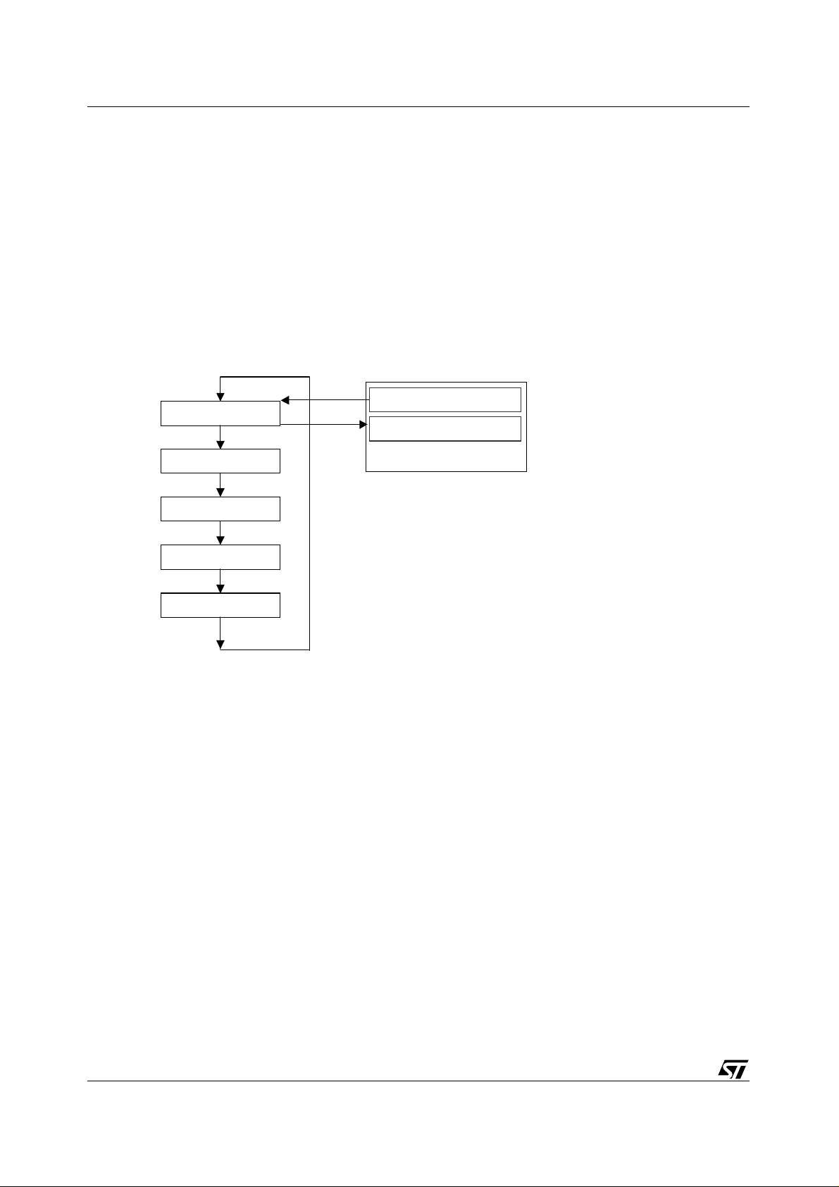
3.1 Modes available (STV0680B-001)
Normal: 20 / 80
Continuous Capture: Ct
Self-Timer: St
Clear All: CL
Re solution: Hr / Lr
Press Mode button
After 30sec of inactivity
Standby mode (u ntethered)
Section 2.2.1
Figure 3 : STV0680B-001modes (CIF camera with 16Mbit SDRAM assumed)
Note that the number of images displayed depends on the sensor and SDRAM type - see
16/63 Version 3.4
Table 3
.
STV0680B + VV6444/6410/6500 Camera modes of operation
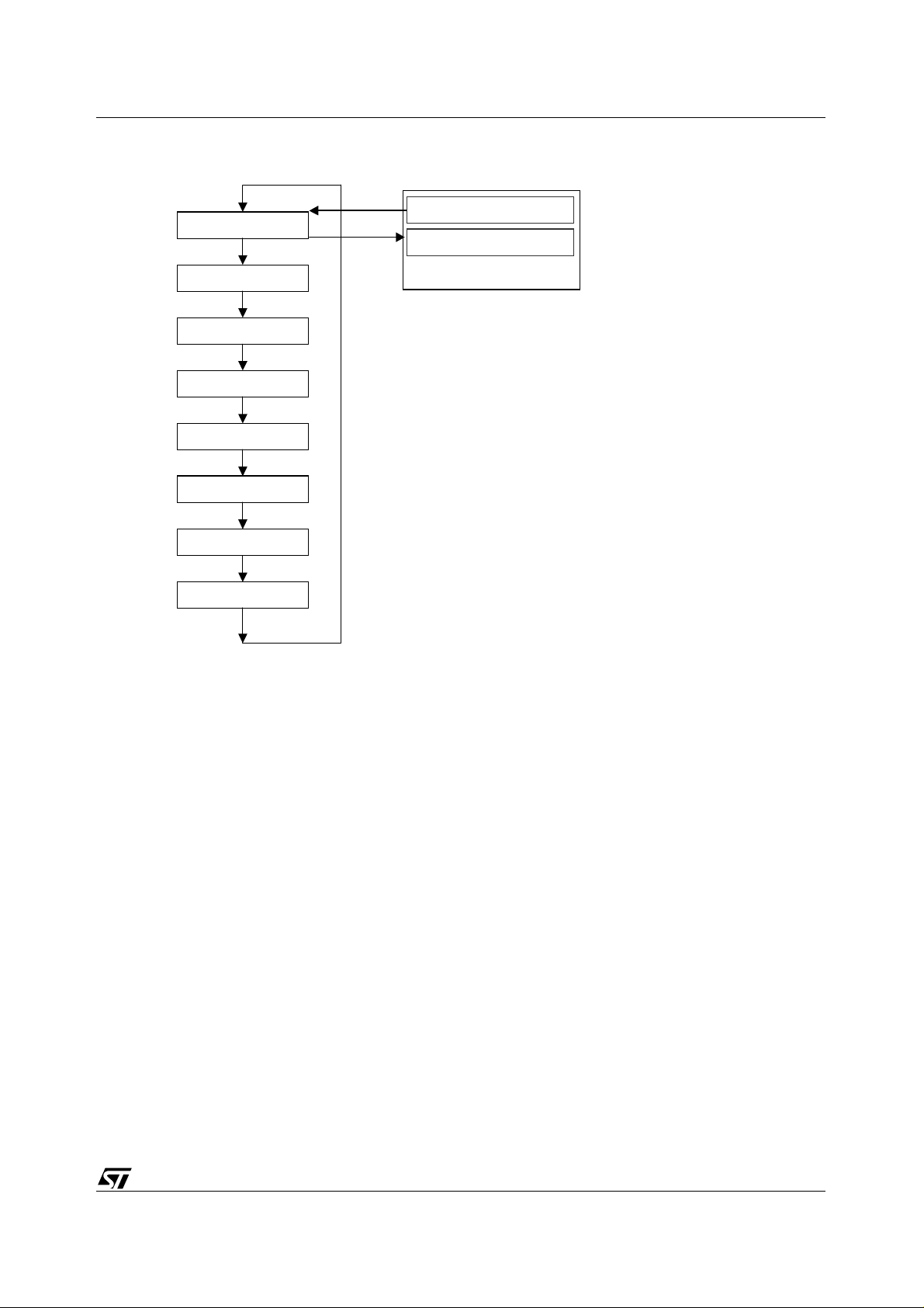
3.2 Modes available (STV0680B-003)
Normal: 20 / 80
Audio Record: Ar
Audio Playback: AP
De lete Last: dA / dP / dC
Continuous Capture: Ct
Self-Timer: St
Clear All: CL
Re solution: Hr / Lr
Press Mode button
After 30sec of inactivity
Standby mode (u ntethered)
Notes:
1. Audio Record only available if audio hardware is fitted
2. Audio Playback only available once an audio clip has been recorded
3. Delete Last displays (only available if audio hardware fitted)
dA - if the last object is an audio clip
dP - if the last object is a picture
dC - if the last object is a continuous capture clip
The mode is inhibited if the camera is empty.
4. Continuous Capture mode is inhibited when the flashgun is enabled
(SW 6 down)
Figure 4 : STV0680B-003modes (CIF camera with 16Mbit SDRAM assumed)
3.3 Description of modes
Note that certain modes are only available using STV0680B-003, and with appropriate hardware
fitted on the camera.
3.3.1 Standby mode (untethered) and Wake-up
On power-up, or wake-up from untethered standby mode, (i.e. by pressing the Mode button), the
camera will beep twice. The LCD will briefly indicate the camera resolution either ‘Hr.’ for high
resolution (80 CIF or 26 VGA images - usi ng 64Mbit memo ry) or ‘Lr’ for low resolution (32 2 QCIF or
107 VGA images - using 64Mbit memory) and then display the number of pictures which may be
taken. Please note that in Low Resolution Mode, although t here can be up to 322 images availab le,
the LCD counter will only go up to 9 9, it will contin ue reporting 99 un til there are less than 99 images
left.
The camera will go back to standby mode either after 30 seconds of inactivity, LED1 will turn off and
the LCD will go blank. This can al so be done (STV 0680B-003 only) by pressing t he mode switch f or
more than 2 seconds.
3.3.2 Normal mode
Pressing the shutter button will take a pi cture . T he camer a wi ll beep. A h igh pi tched beep indi cates
that the picture was taken successfully and the counter will decrement (if there are less than 99
images left to take). A low beep indicates insufficient light to take a picture. A series of beeps
indicates that the camera is full.
Version 3.4 17/63

Camera modes of operation STV0680B + VV6444/6410/6500
Stored pictures may be uploaded t o a PC at any time, whether or not the ca mera is full. Plugging the
USB connector into the camera will cause it to r eset and issue a double b eep but all stored p ictures
will remain. When the USB connector is unplugged the ca mera will go to sleep. When connected to
the PC the camera may still be used in the normal way.
Note
: With the flashgun enabled (STV0680B-003 only) the camera will always take a picture,
whether or not there is sufficient light.
3.3.3 Audio record - Ar
This mode is available on STV0680B-003 only, with audio record hardware fitted.
Pressing the shutter button with in 5 secon ds w ill cause the camera to start recordi ng for as l ong as
the shutter button is pressed down. If the shutter butto n is not pressed withi n 5 seconds the camera
will revert to normal picture taking mode. Whilst recording, the LCD display flashes ‘Ar’. If the
recording stops because the memory is full, the ‘memory full’ audio tone is so unded and the displa y
will stop flashing and display ‘00’. The audio data is digitised and stored in SDRAM.
3.3.4 Audio Playback - AP
This mode is available on STV0680B-003 only, with audio playback hardware fitted.
Pressing the shutter button within 5 seconds will cause the camera to play back the most recent
audio recording. If the shutter button is not pressed within 5 seconds the camera will revert to
normal picture taking mode. Whilst playing, the LCD display flashes ‘AP’.
Once in Audio Playback mode, repeated presses of the shutter button will step the camera through
each of the audio recordings in the camera (most recent first). Keeping the shutter button pressed
down will also cycle through the audio recordings. Pressing the mode button during playback will
stop the audio clip.
Note
: Minimum audio recording length is set to 0.5 seconds.
3.3.5 Delete last object - dA/dP/dC
This mode is available on STV0680B-003 only, with audio record hardware fitted.
If the last object captured was an audio recording 'dA' (delete audio) will be displayed, if the last
object was an image, then 'dP' (delete picture) will be displayed, or, if the last object was part of a
continuous capture sequence, then 'dC' (delete continuous) will be displayed. If the camera is
empty , the mode will be suppressed. The mode works in the same way as ‘CL’ (Clear All), i.e. once
the mode is selected, pressing the shutter button once will cause the camera to b eep and ‘dA’, ‘dP’
or ‘dC’ to start flashing. Pressing the shutter butto n again within 5 seconds will delete the l ast audio
clip, picture or continuous capture sequence.
18/63 Version 3.4

STV0680B + VV6444/6410/6500 Camera modes of operation
3.3.6 Continuous mode - Ct
Pressing the shutter button within 5 seconds will cause the camera to start taking pictures for as
long as the shutter button is pressed down (and the camera is not full). If the shutter button is not
pressed within 5 seconds the camera will revert to normal picture taking mode.
Note: 1 During continuous mode the camera wil l allow picture s to be ta ken regardl ess of the ava ilable light,
which could result in insufficient exposure.
2 In continuous mode, only every alternate field is grabb ed hence capture rate is halved. E.g. 12.5 fps
CIF and 7.5fps VGA
3 On STV0680B-003, Continuous Mode is suppressed w hen the Fl ashGun ena ble signal ( GPI O2) is
high.
3.3.7 Self timer - St
Pressing the shutter button will now start a 10-second self-timer . The camera will issue a short beep
every second and then a longer beep. A further beep will then indicate that the picture has been
taken (high beep - picture successful, low beep - insufficient light, picture not taken). The self-timer
mode can not be selected when the camera is full. The self-timer countdown cannot be stopped
once it has started.
3.3.8 Clearing the camera memory - CL
Pressing the shutter button once will cause the camera to beep and the ‘CL’ to start flashing.
Pressing the shutter button again within 5 seconds will clear all the images/audio clips in the
camera and reset the counter.
3.3.9 Changing picture resolution - Hr/Lr
The resolution option is displayed, either Hr. to change to high-resolution mode (if currently in lowresolution mode) or Lr to change to low-resolution (if currently in high-resolution mode). Press the
shutter button within 5 seconds of selecting the resolution option, the camera will beep and the
display will reset indicating the number of pictures available in the new mode. The picture resolut ion
can be changed at any time, i.e. the camera can store both high and low resolution images.
Version 3.4 19/63
 Loading...