

SGS Thomson Microelectronics STTA9012TV2, STTA9012TV1 Datasheet

STTA9012TV1/2
TURBOSWITCH
TM
ULTRA-FASTHIGH VOLTAGE DIODE
MAINPRODUCTCHARACTERISTICS
I
F(AV)
V
RRM
t
(typ) 65ns
rr
(max) 1.85V
V
F
2 x 45A
1200V
FEATURESAND BENEFITS
ULTRA-FAST,SOFT RECOVERY.
VERY LOW OVERALL POWER LOSSES IN
BOTH THE DIODE AND THE COMPANION
TRANSISTOR.
HIGH FREQUENCY AND/OR HIGH PULSED
CURRENTOPERATION.
HIGHREVERSEVOLTAGECAPABILITY.
LOW INDUCTANCEPACKAGE< 5 nH.
INSULATEDPACKAGE:
Electricalinsulation : 2500V
RMS
Capacitance: <45pF.
K2 A2
K1 A1
STTA9012TV1
ISOTOP
A2
K2K1A1
STTA9012TV2
TM
DESCRIPTION
TURBOSWITCH 1200V drastically cuts losses in
allhighvoltageoperationswhich requireextremely
fast,soft andnoise-freepower diodes.Due to their
optimizedswitchingperformancesthey also highly
decrease power losses in any associated
They are particularly suitable in motor control
circuitries, or in the primaryof SMPS as snubber,
clampingor demagnetizingdiodes. They are also
suitable for secondary of SMPS as high voltage
rectifierdiodes.
switching IGBT or MOSFET in all ”freewheel
mode”operations.
ABSOLUTE RATINGS (limiting values,per diode)
Symbol Parameter Value Unit
V
RRM
V
RSM
I
F(RMS)
I
FRM
I
FSM
T
stg
T
j
ISOTOPand TURBOSWITCH are trademarks of STMicroelectronics.
November1999 - Ed: 6B
Repetitivepeak reverse voltage 1200 V
Non repetitivepeakreverse voltage 1200 V
RMSforwardcurrent 150 A
Repetitivepeak forward current tp= 5 µs F = 5kHzsquare 700 A
Surgenon repetitiveforwardcurrent tp= 10ms sinusoidal 420 A
Storagetemperaturerange - 65 to+ 150 °C
Maximumoperatingjunction temperature 150 °C
1/8

STTA9012TV1/2
THERMAL ANDPOWER DATA (perdiode)
Symbol Parameter Testconditions Value Unit
R
th(j-c)
Junctionto casethermalresistance Perdiode 0.85 °C/W
Total 0.48
Coupling 0.1
P
1
Conductionpowerdissipation I
= 45Aδ=0.5
F(AV)
94 W
Tc=70°C
P
max
Totalpower dissipation
Tc=62°C 104 W
Pmax= P1 + P3 (P3 =10% P1)
STATICELECTRICALCHARACTERISTICS(per diode)
Symbol Parameter Test conditions Min Typ Max Unit
* Forwardvoltagedrop IF=45A Tj = 25°C
V
F
Tj = 125°C 1.3
I
** Reverseleakage current VR=0.8x
R
V
RRM
Vto Thresholdvoltage Ip< 3.I
Tj = 25°C
Tj = 125°C3
Tj = 125°C 1.57 V
AV
2.05
1.85
200
12
Rd Dynamicresistance 6 m
Test pulses : * tp = 380µs, δ <2%
** tp = 5ms ,
δ
<2%
To evaluatethe maximumconductionlossesuse the following equation:
P=V
toxIF(AV)
+rdxI
F2(RMS)
V
µA
mA
Ω
DYNAMICELECTRICALCHARACTERISTICS(perdiode)
TURN-OFF SWITCHING
Symbol Parameter Test conditions Min Typ Max Unit
t
rr
Reverserecovery
time
I
RM
Maximumreverse
recoverycurrent
S factor Softnessfactor Tj = 125°CV
Tj = 25°C
I
= 0.5A IR=1A Irr= 0.25A
F
=1A dIF/dt =-50A/µsVR=30V
I
F
65
115
Tj = 125°C VR= 600V IF=45A
/dt = -360A/µs
dI
F
/dt = -500A/µs50
dI
F
= 600V IF=45A
R
/dt = -500A/µs 1.2
dI
F
60
TURN-ON SWITCHING
Symbol Parameter Test conditions Min Typ Max Unit
t
fr
V
Fp
Forwardrecoverytime Tj = 25°C
I
=45A, dIF/dt =360 A/µs
F
measuredat 1.1× V
Peakforward voltage Tj= 25°C
=45A,dIF/dt = 360A/µs
I
F
=45A,dIF/dt = 500A/µs30
I
F
max
F
900
30
ns
A
-
ns
V
2/8
STTA9012TV1/2
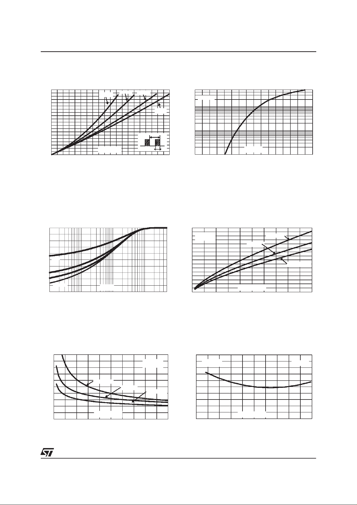
Fig. 1: Conduction losses versus averagecurrent
(perdiode).
P1(W)
100
δ = 0.1
δ = 0.2
δ= 0.5
80
60
δ =1
40
T
20
=tp/T
0
IF(av) (A)
0 5 10 15 20 25 30 35 40 45 50
δ
tp
Fig. 3: Relative variation of thermal impedance
junctionto caseversuspulse duration (per diode).
Zth(j-c)/Rth(j-c)
1.0
0.8
0.6
δ = 0.5
0.4
δ = 0.2
δ = 0.1
0.2
Single pulse
0.0
1E-3 1E-2 1E-1 1E+0 5E+0
tp(s)
Fig. 2: Forward voltage drop versus forward
current(maximumvalues, perdiode).
IFM(A)
500
Tj=125°C
100
10
VFM(V)
1
0.0 0.5 1.0 1.5 2.0 2.5 3.0 3.5 4.0
Fig.4: PeakreverserecoverycurrentversusdIF/dt
(90%confidence,per diode).
IRM(A)
80
VR=600V
70
Tj=125°C
60
IF=IF(av)
50
40
30
20
10
0
0 100 200 300 400 500
dIF/dt(A/µs)
IF=2*IF(av)
IF=0.5*IF(av)
Fig. 5: Reverse recoverytime versus dIF/dt (90%
confidence,perdiode).
trr(ns)
1000
VR=600V
800
600
IF=2*IF(av)
IF=IF(av)
400
200
dIF/dt(A/µs)
0
0 100 200 300 400 500
Tj=125°C
IF=0.5*IF(av)
Fig. 6: Softnessfactor(tb/ta) versusdIF/dt (typical
values).
S factor
1.60
1.40
1.20
1.00
0.80
0.60
IF<2*IF(av)
VR=600V
Tj=125°C
dIF/dt(A/µs)
0 100 200 300 400 500
3/8
 Loading...