

SGS Thomson Microelectronics STTA812G, STTA812DI, STTA812D Datasheet
STTA812D/DI/G
TURBOSWITCH
ULTRA-FASTHIGH VOLTAGE DIODE
MAINPRODUCTCHARACTERISTICS
I
F(AV)
V
RRM
(typ) 50ns
t
rr
(max) 2.0V
V
F
8A
1200V
FEATURESAND BENEFITS
ULTRA-FAST,SOFT RECOVERY.
VERY LOW OVERALL POWER LOSSES IN
BOTH THE DIODE AND THE COMPANION
TRANSISTOR.
HIGH FREQUENCY AND/OR HIGH PULSED
CURRENTOPERATION.
HIGHREVERSEVOLTAGECAPABILITY
INSULATEDPACKAGE: TO-220ACIns.
Electricalinsulation : 2500V
RMS
Capacitance: 7pF.
K
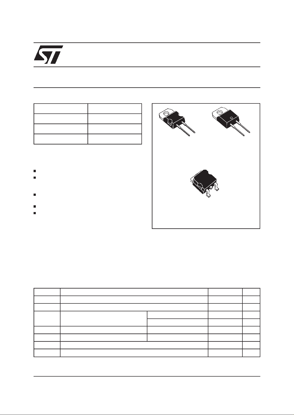
TO-220AC
STTA812D
A
K
K
D2PAK
STTA812G
TO-220ACIns.
STTA812DI
A
NC
A
K
DESCRIPTION
TURBOSWITCH 1200V drastically cuts losses in
all highvoltageoperationswhich requireextremely
fast,softand noise-freepower diodes.Due to their
optimizedswitchingperformancesthey alsohighly
decrease power losses in any associated
They are particularly suitable in motor control
circuitries, or in the primary of SMPSas snubber,
clamping or demagnetizingdiodes. They are also
suitable for secondary of SMPS as high voltage
rectifierdiodes.
switching IGBT or MOSFET in all ”freewheel
mode”operations.
ABSOLUTE RATINGS(limitingvalues)
Symbol Parameter Value Unit
V
RRM
V
RSM
I
F(RMS)
Repetitivepeakreversevoltage 1200 V
Non repetitivepeakreverse voltage 1200 V
RMSforwardcurrent TO-220AC/D2PAK 30 A
TO-220ACIns. 20 A
I
FRM
I
FSM
T
stg
T
TURBOSWITCH is a trademark of STMicroelectronics.
November 1999- Ed: 4C
Repetitivepeakforward current tp = 5µs F = 5kHz square 110 A
Surgenon repetitiveforwardcurrent tp = 10ms sinusoidal 70 A
Storagetemperaturerange - 65 to+ 150 °C
Maximumoperatingjunctiontemperature 150 °C
j
1/10

STTA812D/DI/G
THERMAL AND POWER DATA
Symbol Parameter Conditions Value Unit
R
P
th(j-c)
P
1
max
Junctionto casethermal
resistance
Conductionpowerdissipation
=8Aδ=0.5
I
F(AV)
Totalpower dissipation
Pmax= P1 +P3 (P3 = 10% P1)
TO-220AC/D2PAK
TO-220ACIns.
TO-220AC/D
2
PAK
TO-220ACIns.
TO-220AC/D2PAK
TO-220ACIns.
Tc= 105°C
Tc= 85°C
Tc= 100°C
Tc= 79°C
2.3
3.3
19.5 W
21.5 W
STATICELECTRICAL CHARACTERISTICS
Symbol Parameter Testconditions Min Typ Max Unit
V
F*
I
R**
Forwardvoltagedrop IF=8A Tj = 25°C
Reverseleakagecurrent VR=0.8x
V
RRM
Vto Thresholdvoltage Ip< 3.I
AV
Tj = 125°C 1.35
Tj=25°C
Tj = 125°C 0.6
Tj = 125°C 1.57 V
2.2
2.0
100
4
rd Dynamicparameter 54 mΩ
Test pulses : * tp = 380 µs, δ <2%
** tp= 5 ms ,δ<2%
Toevaluate the maximum conductionlossesusethe following equation :
P=V
toxIF(AV)
+rdxI
F2(RMS)
°C/W
V
V
A
µ
mA
DYNAMICELECTRICAL CHARACTERISTICS
TURN-OFF SWITCHING
Symbol Parameter Testconditions Min Typ Max Unit
t
rr
I
RM
S factor Softnessfactor Tj = 125°CV
Reverserecovery
time
Maximumreverse
recoverycurrent
Tj=25°C
=0.5 A IR= 1A Irr = 0.25A
I
F
=1A dIF/dt =-50A/µsVR=30V
I
F
Tj = 125°C VR = 600V IF=8A
dI
/dt= -64 A/µs
F
dI
/dt= -500A/µs
F
=600V IF=8A
R
/dt= -500A/µs 1.2
dI
F
50
100
12
25
TURN-ON SWITCHING
Symbol Parameter Testconditions Min Typ Max Unit
t
fr
V
Fp
Forwardrecoverytime Tj= 25°C
=8A, dIF/dt = 64 A/µs
I
F
measuredat 1.1×V
Peakforwardvoltage Tj = 25°C
=8A,dIF/dt = 64 A/µs
I
F
=40A,dIF/dt =500 A/µs45
I
F
max
F
900
35
ns
A
-
ns
V
2/10

STTA812D/DI/G
Fig.1: Conductionlosses versusaveragecurrent.
P1(W)
20
18
16
14
δ = 0.1
δ =0.2
δ= 0.5
δ =1
12
10
8
6
4
2
0
0246810
IF(av) (A)
Fig. 3: Relative variation of thermal impedance
junctionto case versus pulse duration.
Zth(j-c)/Rth(j-c)
1.0
0.8
0.6
δ = 0.5
0.4
δ = 0.2
0.2
δ = 0.1
Single pulse
0.0
1E-4 1E-3 1E-2 1E-1 1E+0
tp(s)
Fig. 2: Forward voltage drop versus forward cur-
rent(maximumvalues).
IFM(A)
100.0
Tj=125°C
10.0
1.0
VFM(V)
0.1
0.0 1.0 2.0 3.0 4.0 5.0
Fig. 4: Peak reverse recovery current versus
dI
/dt (90% confidence).
F
IRM(A)
50
VR=600V
Tj=125°C
40
30
20
10
0
0 100 200 300 400 500
dIF/dt(A/µs)
IF=2*IF(av)
IF=IF(av)
IF=0.5*IF(av)
Fig. 5: Reverserecovery time versus dIF/dt (90%
confidence).
trr(ns)
550
500
450
400
350
IF=2*IF(av)
300
250
200
150
100
50
0
0 100 200 300 400 500
IF=0.5*IF(av)
dIF/dt(A/µs)
VR=600V
Tj=125°C
IF=IF(av)
Fig.6: Softnessfactor(tb/ta) versusdIF/dt(typical
values).
S factor
1.40
VR=600V
IF<2*IF(av)
1.20
1.00
0.80
0 100 200 300 400 500
dIF/dt(A/µs)
Tj=125°C
3/10
 Loading...