

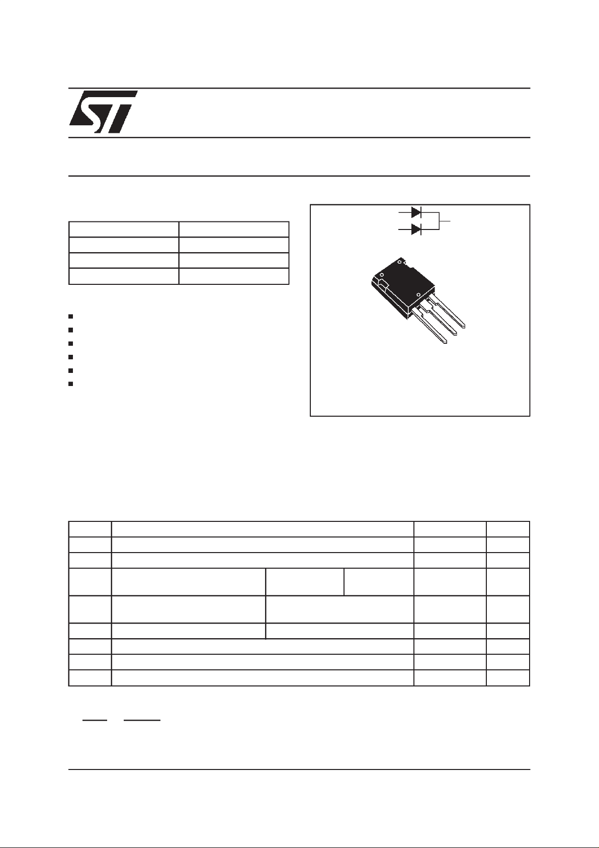
STPS80H100CY
HIGH VOLTAGE POWER SCHOTTKY RECTIFIER
PRELIMINARY DATASHEET
MAINPRODUCTCHARACTERISTICS
I
F(AV)
V
RRM
2 x 40 A
100 V
Tj (max) 175 °C
V
(max) 0.70V
F
FEATURESAND BENEFITS
HIGHREVERSEVOLTAGE
NEGLIGIBLESWITCHINGLOSSES
LOWFORWARDVOLTAGEDROP
LOWLEAKAGECURRENT
HIGHTEMPERATURE
LOWTHERMALRESISTANCE
DESCRIPTION
Dual center tap Schottky rectifier suited for
Switched Mode Power Supplies and high
frequencyDCto DCconverters.
Packaged in Max247, this device is intended for
use in high frequency computer and telecom
converters.
A1
K
A2
A2
K
A1
Max247
ABSOLUTERATINGS
(limiting values,per diode)
Symbol Parameter Value Unit
V
RRM
I
F(RMS)
I
F(AV)
I
FSM
Repetitivepeakreversevoltage 100 V
RMSforwardcurrent 50 A
Averageforwardcurrent Tc= 155°C
δ = 0.5
Surgenon repetitiveforward
tp = 10 ms sinusoidal 400 A
Perdiode
Perdevice
40
80
current
I
RRM
T
T
stg
Repetitivepeakreversecurrent tp = 2µs squareF = 1kHz 2 A
Storagetemperaturerange - 65 to + 175 °C
Maximumoperatingjunctiontemperature* 175
j
°
dV/dt Criticalrate of rise of reversevoltage 10000 V/µs
dPtot
*:
dTj
November 1999 - Ed:1B
1
<
Rth
thermal runawayconditionfor a diode on its own heatsink
(
j−a
)
A
C
1/4
STPS80H100CY
THERMALRESISTANCES
Symbol Parameter Value Unit
R
R
th (j-c)
th (c)
Junctionto case Perdiode 0.7
Whenthe diodes 1 and 2 are used simultaneously:
∆
Tj(diode1) = P(diode1)x R
(Perdiode) + P(diode2) x R
th(j-c)
Total 0.5
Coupling 0.3
th(c)
°
C/W
STATICELECTRICAL CHARACTERISTICS
(perdiode)
Symbol Parameter Tests conditions Min. Typ. Max. Unit
I
* Reverseleakagecurrent Tj = 25°CV
R
R=VRRM
20
Tj = 125°C720mA
V
** Forwardvoltagedrop Tj = 25°CI
F
Tj = 125°CI
Tj = 25°CI
Tj = 125°CI
Pulse test : * tp = 5 ms, δ <2%
** tp = 380 µs, δ <2%
To evaluate the maximum conduction losses use the following equation :
P = 0.56 x I
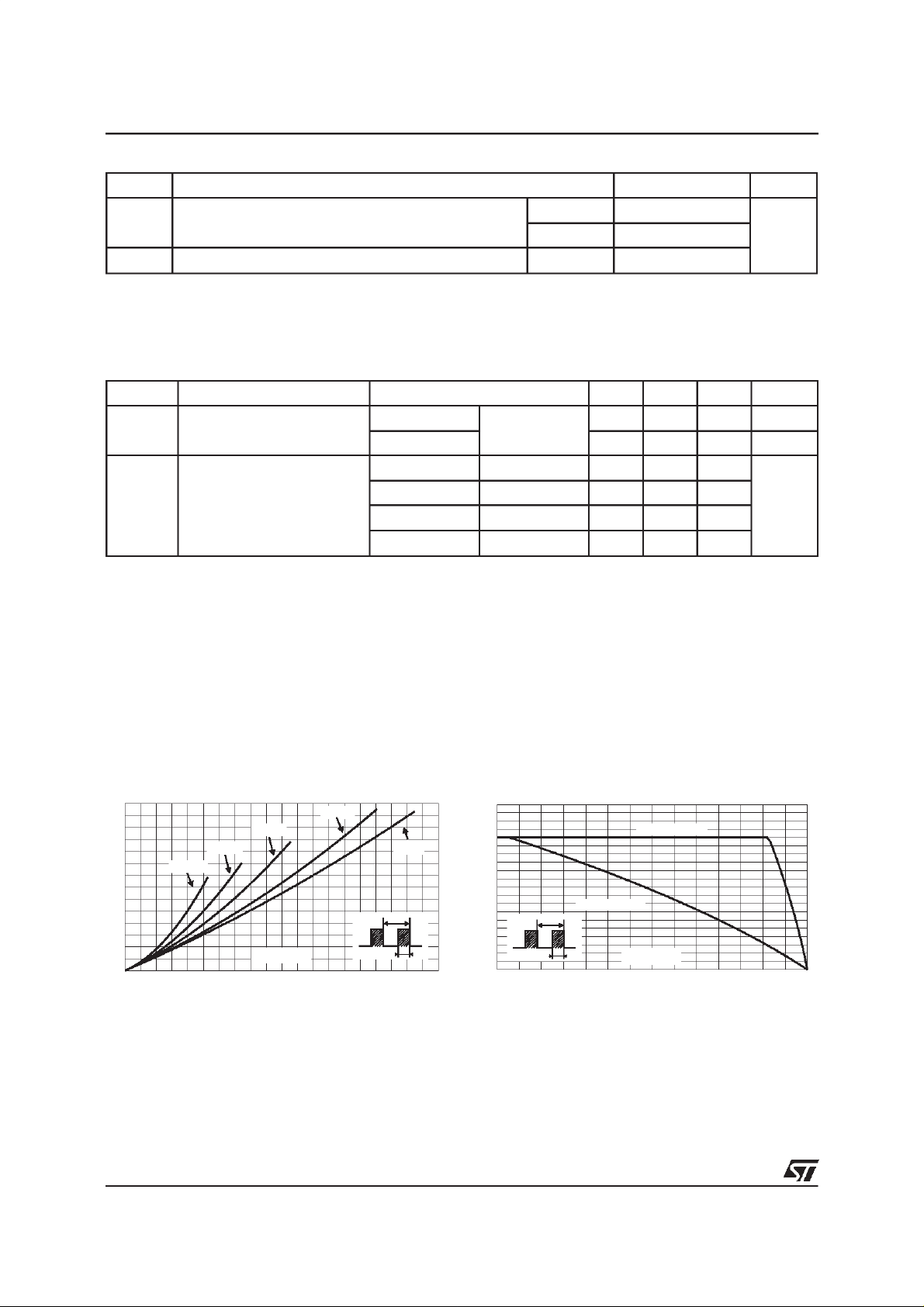
Fig. 1:
+ 0.0035x I
F(AV)
F2(RMS)
Averageforward powerdissipation versus
averageforwardcurrent(per diode).
PF(av)(W)
35
30
25
20
15
10
5
0
0 5 10 15 20 25 30 35 40 45 50
δ = 0.05
δ = 0.2
δ = 0.1
IF(av)(A)
δ= 0.5
δ
=tp/T
δ =1
T
tp
= 40A 0.8 V
F
= 40A 0.65 0.7
F
= 80A 0.94
F
= 80A 0.79 0.84
F
Fig. 2:
Average forward current versus ambient
temperature(δ=0.5, per diode).
IF(av)(A)
50
45
40
35
30
25
20
15
10
5
=tp/T
δ
0
0 25 50 75 100 125 150 175
Rth(j-a)=5°C/W
T
tp
Rth(j-a)=Rth(j-c)
Tamb(°C)
µ
A
2/4
 Loading...