

SGS Thomson Microelectronics STPS745G, STPS745F, STPS745D Datasheet

MAINPRODUCT CHARACTERISTICS
STPS745D/F/G
POWER SCHOTTKY RECTIFIER
I
F(AV)
V
RRM
7.5 A
45 V
Tj (max) 175 °C
(max) 0.57 V
V
F
FEATURESAND BENEFITS
VERYSMALLCONDUCTIONLOSSES
NEGLIGIBLESWITCHINGLOSSES
EXTREMELYFAST SWITCHING
INSULATEDPACKAGE:ISOWATT220AC
Insulatingvoltage= 2000VDC
Capacitance= 12pF
DESCRIPTION
Single Schottky rectifier suited for Switch Mode
Power Supply and high frequencyDC to DC converters.
Packaged either in TO-220AC, ISOWATT220AC
2
or D
PAK, this device is intended for use in low
voltage, high frequency inverters, free wheeling
and polarityprotectionapplications.
ABSOLUTERATINGS
(limiting values)
TO-220AC
STPS745D
A
K
K
D2PAK
STPS745G
A
K
ISOWATT220AC
STPS745F
A
NC
Symbol Parameter Value Unit
V
RRM
I
F(RMS)
I
F(AV)
Repetitivepeakreversevoltage 45 V
RMSforwardcurrent 20 A
Averageforward current
δ
= 0.5
TO-220AC/
2
PAK
D
Tc = 160°C 7.5 A
ISOWATT220AC Tc = 145°C
I
FSM
Surgenonrepetitiveforward
tp = 10ms sinusoidal 150 A
current
I
RRM
I
RSM
Repetitivepeakreversecurrent tp = 2µs square F = 1kHz 1 A
Non repetitivepeak reverse
tp = 100 µs square 2 A
current
Tstg Storagetemperature range - 65 to+ 175 °C
Tj Maximum operatingjunction temperature* 175 °C
dV/dt Criticalrate of rise of reverse voltage 10000 V/µs
dPtot
*:
dTj
June 1999 - Ed: 4D
<
1
Rth(j−a
thermal runawayconditionfor a diode on its ownheatsink
)
1/7

STPS745D/F/G
THERMALRESISTANCES
Symbol Parameter Value Unit
R
th (j-c)
Junctionto case TO-220AC/ D2PAK 3.0 °C/W
ISOWATT220AC 5.5
STATICELECTRICAL CHARACTERISTICS
Symbol Parameter TestsConditions Min. Typ. Max. Unit
* Reverseleakage current Tj = 25°CV
I
R
R=VRRM
100
Tj = 125°C 5 15 mA
* Forwardvoltagedrop Tj = 125°CI
V
F
Tj = 25°CI
Tj = 125°CI
Pulse test : * tp = 380 µs, δ <2%
= 7.5 A 0.5 0.57 V
F
= 15 A 0.84
F
= 15 A 0.65 0.72
F
To evaluatethe conductionlossesuse thefollowingequation:
P = 0.42x I
F(AV)
+0.020I
F2(RMS)
µ
A
2/7
STPS745D/F/G
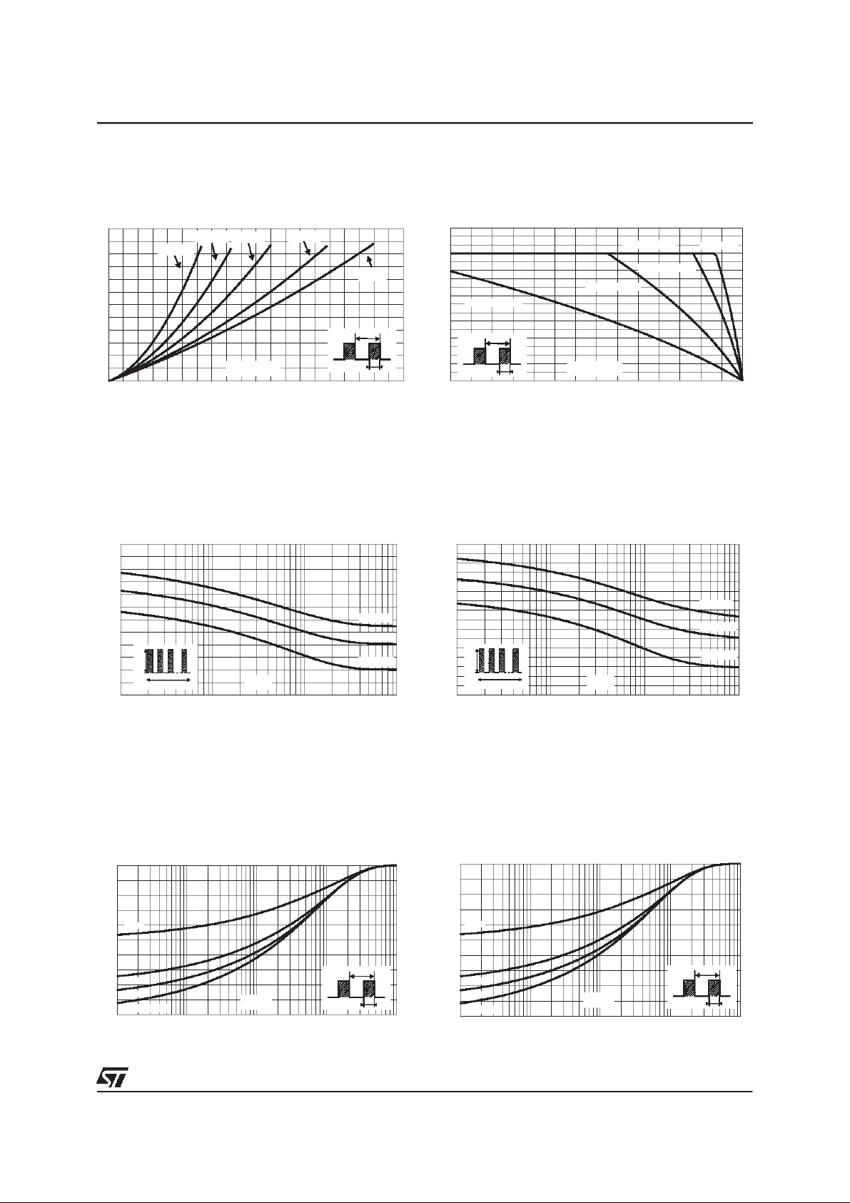
Fig. 1:
Average forward power dissipation versus
averageforwardcurrent.
PF(av)(W)
6
5
4
3
2
1
0
012345678910
Fig. 3-1:
current versus overload duration (maximum
values) (TO-220ACand D
IM(A)
120
100
80
60
40
IM
20
0
1E-3 1E-2 1E-1 1E+0
δ = 0.1
δ = 0.05
IF(av)(A)
δ= 0.5δ = 0.2
δ =1
T
=tp/T tp
δ
Non repetitive surge peak forward
2
PAK).
Tc=50°C
Tc=100°C
Tc=150°C
δ=0.5
t
t(s)
Fig. 2:
Average current versus ambient
temperature (δ = 0.5).
IF(av)(A)
9
8
7
6
5
Rth(j-a)=Rth(j-c)
ISOWATT220AB
Rth(j-a)=15°C/W
Rth(j-a)=40°C/W
TO-220AC
4
3
2
1
0
0 25 50 75 100 125 150 175
Fig. 3-2:
δ
T
=tp/T
tp
Tamb(°C)
Non repetitive surge peak forward
current versus overload duration (maximum
values) (ISOWATT220AC).
IM(A)
80
70
60
50
40
30
20
IM
10
0
1E-3 1E-2 1E-1 1E+0
δ=0.5
t
t(s)
Tc=50°C
Tc=100°C
Tc=150°C
Fig. 4-1:
impedancejunction to caseversus pulse duration
(TO-220ACand D
Relative variation of thermal transient
2
PAK).
Zth(j-c)/Rth(j-c)
1.0
0.8
δ= 0.5
0.6
0.4
δ
=tp/T
T
tp
δ = 0.2
0.2
δ = 0.1
Single pulse
0.0
1E-4 1E-3 1E-2 1E-1 1E+0
tp(s)
Fig. 4-2:
Relative variation of thermal transient
impedancejunction to case versus pulse duration
(ISOWATT220AC).
Zth(j-c)/Rth(j-c)
1.0
0.8
δ = 0.5
0.6
0.4
δ
=tp/T
T
tp
3/7
δ = 0.2
0.2
δ = 0.1
Single pulse
0.0
1E-3 1E-2 1E-1 1E+0 1E+1
tp(s)
 Loading...